

Abstract
It has been recently shown that chestwall recurrence of breast cancer and many other superficial diseases can be successfully treated with the combination of radiation, chemotherapy and hyperthermia. Conformal microwave antenna array for hyperthermia treatment of large area superficial diseases can significantly increase patient comfort while at the same time facilitate treatment of larger and more irregularly shaped disease. A large number of small efficient antennas is preferable for improved control of heating, as the disease can be more accurately contoured and the lower power requirement correlates with system reliability, linearity and reduced cost. Thus, starting from the initially proposed square slot antennas, we investigated new designs for multi-fed slot antennas of several shapes that maximize slot perimeter while reducing radiating area, thus increasing antenna efficiency. Simulations were performed with commercial electromagnetic simulation software packages (Ansoft HFSS) to demonstrate that the antenna size reduction method is effective for several dual concentric conductor (DCC) aperture shapes and operating frequencies. The theoretical simulations allowed the development of a set of design rules for multi-fed DCC slot antennas that facilitate conformal heat treatments of irregular size and shape disease with large multi-element arrays. Independently on the shape, it is shown that the perimeter of 10cm at 915 MHz delivers optimal radiation pattern and efficiency. While the maximum radiation is obtained for a circular pattern the rectangular shape is the one that feels more efficiently the array space.
1 INTRODUCTION
Breast cancer, the most common form of cancer in women, killed in 2005 40,000 people in the United States of America [1]. With an estimated 200,000 new cases per year, chest wall recurrence of breast cancer following surgery and varies between 5 and 35%, while its response to treatment varies from few months to 30 years depending on many factors such as the efficacy of the initial local control but also the genetic signature of the cancerous cells. In any case the addition of a series of hyperthermia treatments at 40–43°C significantly improves the effects of radiation and/or chemotherapy without affecting the long term toxicity. Thus improvements in the heat delivery techniques and temperature monitoring capabilities directly reduce the variance of the present survival rate and move its median above the 2 years mark.
Microwave is the technique of choice for treating cancer spreading on a large area but with limited depth. Microwave arrays on flexible printed circuit boards can be easily combined with temperature monitoring sensors and radiation therapy delivery systems to simultaneously heat and irradiate the tumors for a more effective treatment modality [2]. Differently from the commercially available waveguides, the hybrid applicator developed at Duke University for concurrent microwave heating and brachytherapy treatment of large area surface is light, conformable, comfortable and able to cover any large area. In addition, by integrating multielement array to deliver the heat with temperature monitoring arrays using flexible circuit board technology, the applicator offers an inexpensive solution to improve the quality and the easiness of hyperthermia treatment. We report the recent developments toward the final prototype for large scale clinical trial: the efforts were focused on optimizing the individual components of the multilayer applicator for improved overall performance and compatibility with the HDR brachytherapy instrument currently used in the Radiation Oncology department at the Duke University Medical Center in Durham USA The efforts were focused on the optimization of the heating element of the array to be able to conform to the various shape needed to contour the edges of the disease and avoid critical tissues, such scars, flaps, blisters and open wounds.
2 THE HYPERTHERMIA SYSTEM
Current commercial hyperthermia waveguide applicators are not able to accurately and completely contour the superficial disease. The repeatability of the treatment and its quality, is seriously affected while the patient discomfort increases. In addition, many patients have a skin flap that was surgically applied to cover the tissue exposed after the removal of the breast and the surrounding tumor bed. The flap has limited perfusion, thus the risk of scarring and blistering is elevated in such regions.
2.2 ThermoBrachytherapy Surface Applicator
The use of an array of flexible material, as shown in Figures 1 and 2, addresses the issue of comfort and effectiveness. Each antenna can be easily turned ON/OFF to achieve a desired 2D pattern of microwave power distribution.
Figure 1.
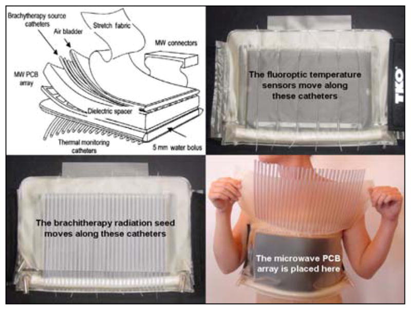
Multilayered vest for combined hyperthermia and brachytherapy treatment of superficial disease
Figure 2.
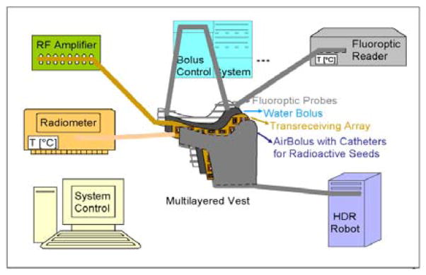
System schematics of the HT+RT system
The system is composed by a multilayer vest, called ThermoBrachytherapy Surface Applicator (TBSA), a heating system, a temperature monitor based on fluoroptic sensors, a brachtherapy robot and a water conditioning system. In the near future a radiometric array will be added to monitor deeper temperatures.
2.2 Brachytherapy
Photons from the HDR source inside the brachytherapy tubing undergo rapid attenuation as they travel through the TBSA applicator layers and also generate secondary electron emissions due to scattering from the edges of the slots in the thin (0.15 mm) copper PCB array. Thus, it is important to quantify the impact of the TBSA applicator on patient radiation dosimetry calculations. As shown in Figures 3 and 4, radiation dose calculation on a tissue equivalent CT phantom were calculated assuming a “uniform” radiation dose of 100 cGy minimum was delivered to a 1 cm target region through the brachytherapy tube array with a Varian GammaMed 12i afterloader (Varian Med. Sys., Palo Alto, CA).
Figure 3.
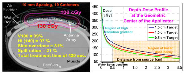
Experimental setup, and Figure 4 (right) calculated dose attenuation for brachytherapy study of TBSA
It was confirmed the need of a 5–10 mm water bolus to reduce the high radiation exponential decay to a lower and more controllable linear dose region. The PCB attenuation coefficient was measured as 2.95±0.03%. and it using OneDose™ dosimeters indicating that the copper PCB does not significantly attenuate the beam.
2.2 Water Bolus
The water on the skin is kept at a constant temperature by the water bolus and its conditioning system which, in addition of controlling thickness of the bolus for better coupling of radiation and microwave energy, removes the air bubbles that would significantly affects the power deposition. The modulation of the water temperature also allow for a control of the depth profile, moving up and down the highest peak of the thermal distribution in the target tissue, allowing for a quasi-3D control of the heating pattern.
2.3 Microwave Antenna Array
In the past array of multi-fed square slot patches dual concentric conductor antenna were proposed as a simple and efficient radiator for superficial microwave hyperthermia. As explained in [3], a voltage between the center patch and the ground plane can excite a radiating slot mode, which propagates into the tissue. The choice of square geometry is dictated by maximizing space utilization for most uniform power deposition patterns in array configurations. Extensive studies of a similar ring slot antenna configuration have been reported in the literature as they are extensively used in radars and communications. While the square antenna patches are ideal for compact and regular distribution of the heating elements, their shape is not suitable to contour the armpit, shoulder and neck region. Thus there is a need to better understand the functioning of multifed slot antennas and investigate their ability in delivering the microwave power in a specific heat deposition pattern which could accommodate more complex shapes. At the same time, the necessity of controlling the power delivered with the highest possible resolution while maintaining antenna efficiency not to overheat the feeding lines on PCB, justifies the need for a smaller antenna.
3 SHAPE AND SIZE OPTIMIZATION
The DCC aperture is a particular ring-slot configuration fed simultaneously on all four sides for optimum near-field power deposition in lossy media. To avoid unwanted phase addition between antennas, the array is not driven coherently, so the boundary conditions are the same of a single antenna. In the case of a 3cm × 3cm square DCC antenna and muscle tissue (εr = 51) at 915 MHz, the near field occurs in the Fresnel region, when r = 7.8cm ≤ 2D2/λm, where r is the distance from an antenna of side D and λm is wavelength in the medium, clearly our case. Far field simplifications cannot be used in the near field so the study and design of the DCC relies heavily on numerical calculation and the power distribution can be better understood in a Cartesian coordinate system. In addition the evanescent fields are strongly affected by discontinuities close to the antenna, so feedlines and changes of dielectric properties in the materials above/below the slot can significantly change the radiated power pattern. A very rough estimation of the effective permittivity, εeff ≈ (1+51)/2, leads to a value of λg ≈ 5.9 cm, which is half the typical DCC ring circumference. So the fundamental mode at which the 3cm DCC antenna could radiate efficiently is approximately 450MHz. All multiples of that frequency will be also be able to radiate (Figure 5). When the patch is fed simultaneously from all four sides, the fields in the slots overlap. At 915 MHz the metal edge currents and the slot E field each travel a half wavelength to reach the next side feed, so the phase is rotated 180°.
Figure 5.

Field distribution in a multi-fed squared slot
In addition, as microwave currents accumulate at the edges and corners, the sharp corners of the square ring accentuate the field peaks. At the antenna-muscle interface, the pattern of radiated power, described by the Specific Absorption Rate (SAR) distribution, mimics the shape of the square slot – alternating maximum values at the corners and minima at the center of each side. In the center of the patch there is no power as the currents flow only along the patch edges. However, as they travel omnidirectionally deeper into muscle, the EM waves generated by the edge currents sum in the center of the patch forming a standing wave along the axis perpendicular to the antenna (z-axis). For a homogeneous medium, the typical SAR pattern is represented in Figure 6. Eventually thermal conduction and perfusion flatten the temperature evenly across the target region
Figure 6.
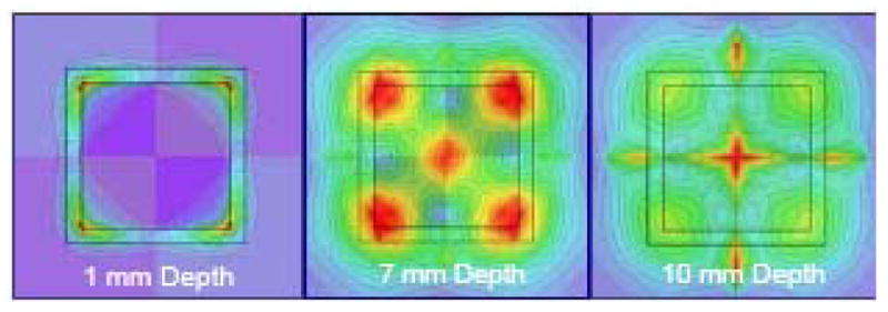
SAR distribution at various depth planes
4 ANTENNA SHAPE AND SIZE
When designing a symmetric regular polygon, the feedlines must be located at the center of the sides of the polygon and the symmetry causes the pattern to conform to the shape of the polygon. The phases of the injection signal must coherently add up to the incoming wave so to is maximum transfer of energy.
Unfortunately, in the case of the DCC, this condition would force the slot antenna to be very large compromising the ability to smoothly contour the disease and the size would reduce the power density. Thus, at the expense of optimal efficiency, the size of the antenna is reduced, but if the antenna does not shrink too much, the travelling wave still gains from the injected power. We simulated several shapes shown in Figure 7 and the results of the simulated SAR pattern at 5mm depth in the treated tissue are shown in Figure 8. The simulation model included a target 1cm deep. The addition of a 5mm bolus clearly smoothens the shape, but the overall power deposition is acceptable considering that the treatment region is usually right at the surface of the skin.
Figure 7.
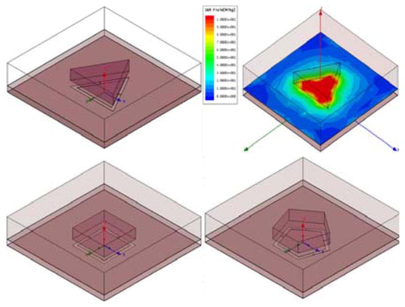
The Ansoft HFSS models of the DCC shapes
Figure 8.
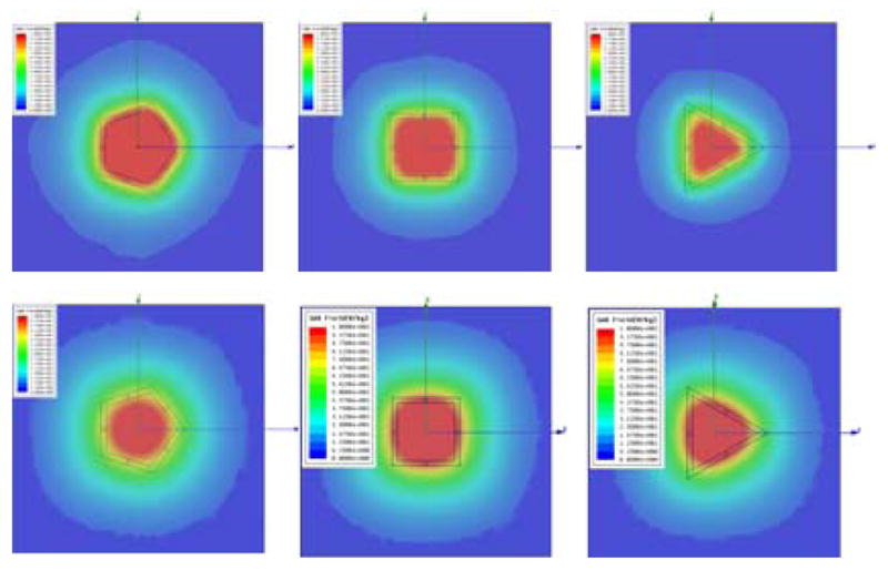
SAR at 5mm in tissue with and without bolus
3.1 Optimal size of the DCC
The size of each of the DCC was also optimized. As the side length changes, the power deposition is affected. As expected, what actually counts is the overall perimeter of the slot. Independently of the shape and the number of sides, the optimal perimeter is 10cm. When the model contains a more complex target medium, which includes skin and all the plastics of the jackets, the optimal perimeter length is 10–12cm as shown in Figure 10–11. While the square antenna provides the best compacting and uniformity properties, it is not the most efficient as the total power in the target increases with the number of sides. As the polygon approaches the circular pattern, the power reaches its optimal value. However a circular pattern does allow a tight fitting in the array.
Figure 10.
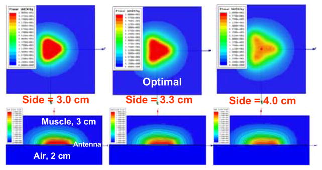
SAR distribution for various perimeters
Figure 11.
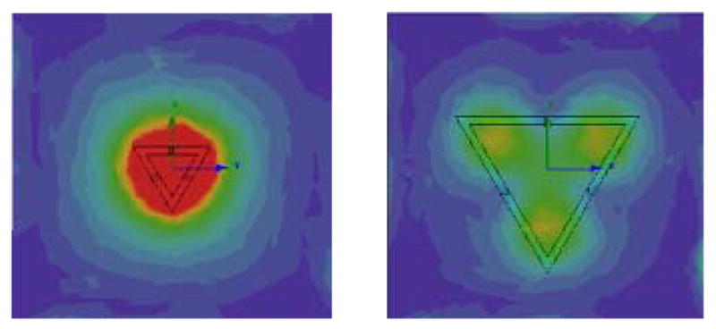
Problems with too short or too long slots
4 CONCLUSION
A hybrid system that combines radiation therapy with hyperthermia for improved treatment of large superficial diseases is presented. To accurately treat critical regions such as flaps and blisters, we specifically designed and optimize multifed slot antennas of various shapes. In this paper the theory of resize and reshape multifed slot antennas for superficial disease is presented. It is shown that, independently on the shape of the antenna, the overall slot length is the determining factor for optimal shape reconstruction at depth and efficient power deposition. A total perimeter length of 10–12 cm is shown to be optimal for slot antenna designed for 915MHz. It is also shown that the total power deposited in the target area increases as the number of sides increases in polygonal-shaped DCCs to achieve a maximum for circular slots which do not compact easily in an array. The results have been applied in a clinical prototype that significantly improve the coverage of critical areas while sparing viable tissue and reducing patient discomfort.
Figure 9.

Power efficiency for various slot length
Acknowledgments
This effort was supported by NIH Grants R44 CA104061 and RO1 CA70761. Our group has a deep appreciation of the strong collaborations with Bionix, Ansoft, Agilent and Aprel that supported our research with much needed hardware and software. We also thank Roberto Berruti of Schinetti S.R.L., Turin, Italy who proposed the efficient multi-fed water bolus by sharing his knowledge in irrigation systems.
References
- 1.Cancer facts and figures. Am Cancer Soc 2005 [Google Scholar]
- 2.Overgaard J. Simultaneous and sequential hyperthermia and radiation treatment of an experimental tumor and its surrounding normal tissue in vivo. International Journal of Radiation Oncology Biology Physics. 1980;6:1507–1517. doi: 10.1016/0360-3016(80)90008-5. [DOI] [PubMed] [Google Scholar]
- 3.Rossetto F, Diederich CJ, Stauffer PR. Thermal and SAR characterization of multielement dual concentric conductor microwave applicators for hyperthermia, a theoretical investigation. Medical Physics. 2000;27(4):745–753. doi: 10.1118/1.598937. [DOI] [PubMed] [Google Scholar]