

Abstract
Nanomachines activated by a pH change can be combined with polymer coatings on mesoporous silica nanoparticles to produce a new generation of nanoparticles for drug delivery that exhibits properties of both components. The nanovalves can trap cargos inside the mesoporous silica nanoparticles without premature release and only respond to specific stimuli, resulting in a high local concentration of drugs at the site of release. The polymer surface coatings can increase the cellular uptake, avoid the reticuloendothelial uptake, provide protected space for storing siRNA, and enhance the biodistribution of nanoparticles. Two nanovalve-polymer systems are designed and their successful assembly is confirmed by solid state NMR and thermogravimetric analysis. The fluorescence spectroscopy results demonstrate that the controlled release functions of the nanomachines in both of the systems are not hindered by the polymer surface coatings. These new multifunctional nanoparticles combining stimulated molecule release together with the functionality provided by the polymers produce enhanced biological properties and multi-task drug delivery applications.
1. Introduction
Over the past decade, mesoporous silica nanoparticles (MSN) have become a promising platform for therapeutic applications.1, 2 Benefitting from the high surface area, large pore volume, nontoxicity and well-developed silanol chemistry derivatization, a variety of surface and interior modifications have been applied to MSN to perform on-demand drug delivery, fluorescence imaging and active targeting.3, 4 Among the various functionalizations of MSN,5–8 multiple methods have been developed to fulfill the on-demand release of payloads, including nanomachine constructions,7, 9 nanocrystal cappings10 and macromolecule cappings.11 For nanomachine constructions, the pore openings of mesoporous structure are blocked by functional groups that have variable binding under different conditions. Upon applying external or internal biological stimuli such as light, magnetic field, pH change or redox change, the pore openings can be readily closed or opened and therefore provide a smart drug delivery system that operates in a controlled fashion.5, 6, 12, 13
In addition to molecular capping agents, various surface coating agents such as polymers and lipid bilayers14–18 have been applied to mesoporous silica nanoparticles to introduce unique functions or to optimize their biological behavior. One example involves grafting polyethylene glycol on MSN surface in order to avoid uptake by the reticuloendothelial system, increase its blood circulation time and improve its biodistribution properties.15, 18, 19 Moreover, the surface coating agents can provide useful storage space for carrying large molecules such as small interfering RNA (siRNA) and DNA molecules to conduct gene therapies.14, 16, 20 It would be ideal if the surface coatings could be incorporated with the controlled-release capping systems to deliver both nucleic acids and small therapeutic molecules simultaneously, presenting a multi-functional delivery platform with enhanced biological properties.
In this study, we investigate for the first time whether the surface coating strategy is compatible with the controlled-release systems. Two polymer coated MSN models were incorporated with pH responsive nanovalves to examine the functionality of the nanomachines in the combined system. The first model is based on 120 nm MSNs with an acid-responsive nanovalve and a small molecular weight polyethylene imine (PEI) coating (Figure 1A). The nanovalves are bonded on the silica surface, and keep the nanopores closed under neutral pH but open them when pH is decreased.12 A 1.8 kDa PEI is utilized in this model due to its efficiency in delivering siRNA with minimal cytotoxicity and enhanced cellular uptake.14, 16, 20 As for the second model, 50 nm MSNs with polyethylene imine-polyethylene glycol (PEI-PEG) co-polymer coatings were combined with a nanovalve that opens at pH 5 (Figure 1B). The 50 nm sized MSN with PEI-PEG copolymer coating has demonstrated excellent properties in delivering drugs at in vivo levels with a high passive accumulation rate at the tumor site, thanks to the enhanced permeability and retention effect (EPR effect).15 To optimize the delivery capacity of anticancer drugs, it would be ideal to incorporate a controlled release nanomachine. Therefore, a nanovalve that opens at pH 5 is employed, and together with the co-polymer coated MSN, is chosen as the second model for examining the operations of nanomachines with the polymer coating. We demonstrate for the first time that through proper design, the nanomachines can be integrated into the polymer coated MSN system, and are capable of releasing the cargos inan on-demand fashion.
Fig. 1.
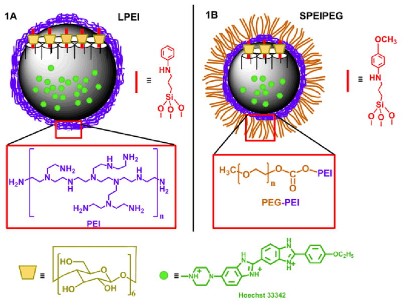
Depictions of the two fully-assembled polymer-nanomachine systems (LPEI group 1A, SPEIPEG group 1B) based on mesoporous silica nanoparticles. In the LPEI group, the particles are about 120 nm in diameter and the polymer coating is PEI. The nanomachine stalk structure is shown on the right side of the particle. In the SPEIPEG group, the particle size is about 50 nm and a PEI-PEG co-polymer is coated on the particle surface. For both of the groups, Hoechst 33342 is the cargo for the release study and the α-cyclodextrin is used as the cap on the two types of stalks.
2. Experimental Section
Materials
Cetyltrimethylammonium bromide (CTAB) (95%, Aldrich), Pluronic F127 (Aldrich), Tetraethyl orthosilicate (TEOS) (98%, Aldrich), polyethyleneimine (PEI) (1.8kD, Aldrich), 4-(dimethylamino) pyridine (99% Aldrich), N,N′-disuccinimidyl carbonate (95%, Aldrich), poly(ethylene glycol) methyl ether(m-PEG) (MW 5kD, Aldrich), toluene(99.5%, Aldrich), methanol (99.9%, Firsher), N,N-Dimethyl formamide (DMF) (anhydrous, 99.8%, Aldrich), triethylamine (99.5%, EMD), ethanol (200 proof, Pharmaco-AAPER), N-phenylaminopropyl trimethoxysilane (PhAPTMS) (95%, Gelest), 3-iodopropyltrimethoxysiliane (IPTMS) (95%, Gelest), p-anisidine (99%, Aldrich), bisBenzimide H 33342 trihydrochloride (Hoechst 33342) (97%, Aldrich), α-cyclodextrin (α-CD) (98%, Aldrich), 3-(trihydroxysilyl)propyl methylphosphonate monosodium aqueous solution (42%, Aldrich), Phosphate-Buffered Saline (PBS) (pH 7.4, Invitrogen). All chemicals were reagent grade and used without further purification or modification.
Characterization
Transmission electron microscopy (TEM) was carried out on a JEM1200-EX (JEOL) instrument. UV-vis spectra were collected by a Cary 500 UV-vis-NIR spectrophotometer. The release profiles were recorded by an Acton Spectra Pro 2300i CCD. 13C CPMAS NMR spectra were obtained by a Bruker DSX-300 MHz Spectrometer with a 4 mm double resonance Bruker probe head. Ziconium oxide 4 mm rotors were used with Kel-F caps. Thermogravimetric analysis (TGA) was performed by a Pyris Diamond TG/DTA (Perkin-Elmer Instruments). N2 adsorption-desorption isotherms were collected on a Quadrasorb SI surface area analyser and the BET model was used to calculate the surface areas. The X-ray powder diffraction (XRD) was performed on a Panalytical X’Pert Pro Powder X-ray Diffractometer (CuKa radiation).
Synthesis of MSN
The first system based on the “large” 120 nm MSN with PEI coating is denoted as the LPEI group. The second model using the smaller 50 nm MSN with the PEI-PEG co-polymer is called the SPEIPEG group.
The mesoporous silica nanoparticle for the LPEI group was synthesized according to a well-established procedure.2, 4, 6 CTAB (250 mg) was added into H2O (120 mL) with NaOH solution (875 μL 2M). The solution was then heated to 80 °C and maintained at the temperature for half an hour before TEOS (1.2 mL) was added slowly into the solution with vigorous stirring. After 20 min, 3-(trihydroxysilyl)propyl methylphosphonate (300 μL) was added and the reaction was kept at 80 °C for another two hours. The synthesized particles were collected and washed with water and methanol. To extract the templating agents, the particles were suspended in methanol (60 mL) with concentrated HCl (2.3 mL) and refluxed at 60 °C overnight. The as-synthesized particles have a lattice distance of about 4.1 nm and the pore size of the mesoporous structure is ~ 2.2 nm.
The synthesis of smaller-sized mesoporous silica nanoparticles was slightly different.15 Pluronic F127 (200 mg) was dissolved in the H2O solution together with CTAB and NaOH. It was then heated to 80 °C for 30 min before TEOS (1.2 mL) was added. After 20 min, 3-(trihydroxysilyl)propyl methylphosphonate (300 μL) was added and the reaction was kept at 80 °C for two hours before centrifugation and washing.
LPEI Surface Modification
For the attachment of nanomachine stalks in LPEI-1 and LPEI-3, the thread molecule PhAPTMS was directly bonded to the silica surface by reacting with the particles in toluene.12 PhAPTMS (30 μL) was added into 100 mg particles in toluene (10 mL). It was then heated to 75 °C and refluxed under nitrogen gas at for 24 h. The aniline-modified particles were then washed and dried for later use.
The polymer coating was applied for both LPEI-2 and LPEI-3. As-prepared particles (50 mg) with (LPEI-3) or without the nanomachine stalk (LPEI-2) were dissolved in methanol (5 mL) and mixed with PEI ethanol solution (1.8 kD, 5 mL, 2.5 mg/mL) for half an hour. The coating procedure was repeated before washing with ethanol and water.
SPEIPEG Surface Modification
The nanomachine stalk molecule for SPEIPEG-1 and SPEIPEG was synthesized by reacting p-anisidine (0.123g), IPTMS (40 μL) and triethylamine (420 μL) in toluene (15 mL) at 75 °C under N2 gas for 24 h. As-synthesized small particles (100 mg) in toluene (15 mL) were added into the stalk solution and reacted at 75 °C under N2 gas for 24 h. The thoroughly washed particles were then suspended in H2O (120 mL) and methanol (120 mL) with NH4NO3 (0.8 g) to remove the surfactants Pluronic F127 and CTAB, prior to washing and drying. Since SPEIPEG-2 is not decorated by nanomachines, only the surfactant extraction part was performed.
The PEI-PEG co-polymer coating for SPEIPEG-2 and SPEIPEG-3 was performed by electrostatically absorbing PEI onto the silica surface and reacting with the activated m-PEG.4,15 Particles (50 mg) after surfactant extraction were mixed with PEI ethanol solution (1.8 kD, 5 mL, 2.5 mg/mL) for half an hour. This step was repeated again and the particles were reacted with activated m-PEG (250 mg) in DMF (5 mL) for 24 h before centrifugation (15000 rpm, 30 min) and washing.
Cargo Loading and α-CD Capping
Cargo loading was carried out by suspending as-prepared particles (20 mg) in Hoechst 33342 solution (2 mL, 1mM buffered water solution) for 24h. Nanomachine stalk-modified samples were added with α-CD (40 mg) and stirred for another 24 h to cap the nanovalves. All samples were washed repeatedly with PBS buffer to remove dye molecules on the silica surface and polymers.
Time-resolved Fluorescence Spectroscopy Release Profile Measurements
Dye loaded sample (4 mg) was weighed and carefully placed in a corner of a cuvette before PBS (6 mL) buffer was added. A 376 nm excitation laser beam was used to excite the emission of Hoechst 33342, and the solution fluorescence spectra were recorded continuously by a spectrophotometer. After collecting a baseline, the solution pH was tuned to 3.5 in the case for LPEI and 5 in the SPEIPEG group to activate the acid nanovalves. Upon the completion of cargo release, the UV-vis absorption spectrum of the supernatant was measured and the dye concentration was calculated using Beer’s law. The mass of cargo molecules being released was obtained and the corresponding weight percent of cargo to the particle was calculated.
3. Results and Discussion
Two polymer-nanomachine combined systems are studied in this paper. The first system is based on the 120 nm MSN with PEI coating and an acid nanovalve that opens at pH 3.5. This model is denoted as the LPEI group and a scheme is shown in Figure 1A. The particles used in the second system are about 50 nm in diameter with the PEI-PEG co-polymer. An acid nanovalve12 that operated at the pH of lysosomes21 in the in vitro study is utilized as the nanomachine. This system is called as SPEIPEG group and is illustrated in Figure 1B.
3.1. Design and Nanomachine Operation of LPEI group
3.1.1 System Construction
For the purpose of comparison, three samples were synthesized in the LPEI group. As shown in Figure 2A, LPEI-1 has only the nanomachine construction on MSN, LPEI-2 is PEI coated MSN without any nanomachine attachment, and LPEI-3 is the fully-assembled system which has both the nanomachine modification and the PEI polymer coating. LPEI-1 is used in order to estimate the nanomachine performance, and LPEI-2 is used as a control. The synthesis procedures for the derivatized nanoparticles are also illustrated in Figure 2.
Fig. 2.
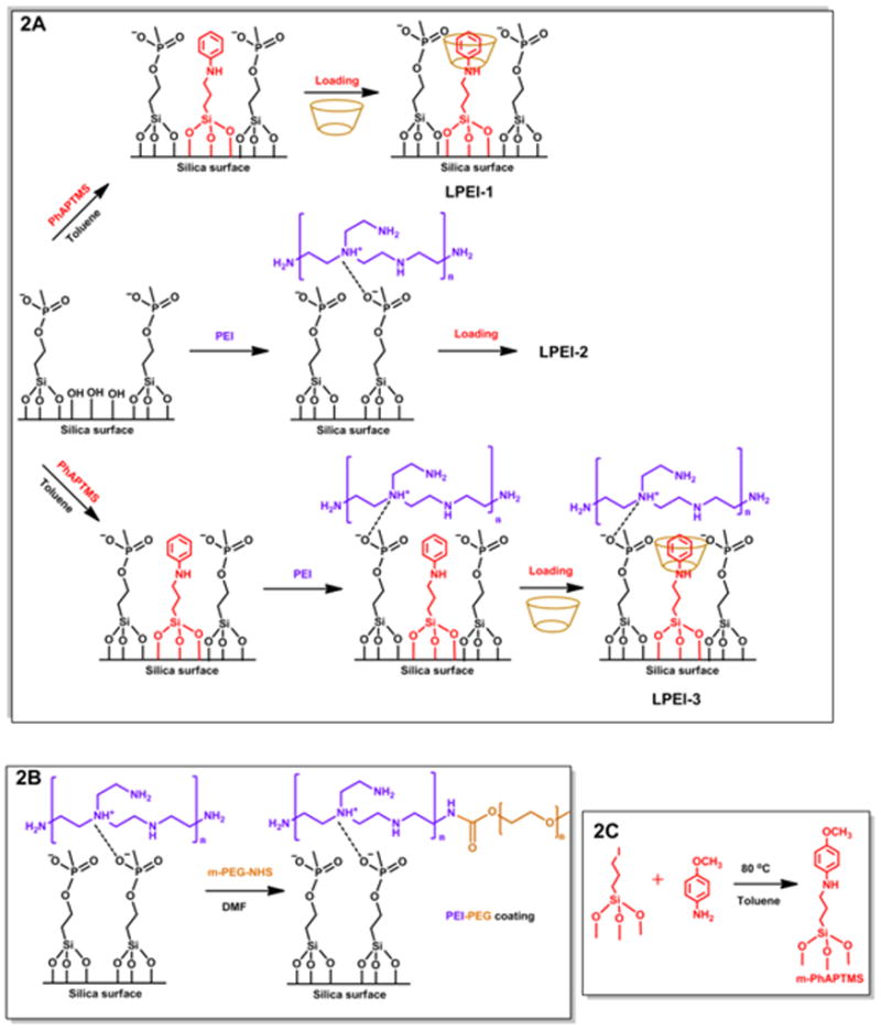
Synthesis procedures and sample names for the LPEI group (2A). LPEI-1 has only the nanomachine modification, LPEI-2 has only the PEI surface coating, and LPEI-3 has both. Similar naming is used for the SPEIPEG group: SPEIPEG-1 has only the acid nanovalve, SPEIPEG-2 has only the PEI-PEG coating, and SPEIPEG-3 has both the nanovalves as well as the PEI-PEG co-polymer coating. In the SPEIPEG group, the overall synthesis steps are similar to that of the LPEI group, only that the polymer and nanovalves used are different. The detailed synthesis steps for the PEI-PEG co-polymer and the nanovalve stalk are shown in Figure 2B and Figure 2C respectively.
In the LPEI group, the nanomachines are composed of two parts: a bulky cyclodextrin moiety and an aromatic amine “stalk”. The stalk is covalently bonded to the silica surface via silanol reaction and the cyclodextrin cap is threaded onto the stalk. The host-guest binding constant between the stalk and the cyclodextrin molecule varies under different pH and renders a functional nanomachine next to the mesopore opening.22 At neutral pH, the cyclodextrin encircles the stalk via a supramolecular interaction, blocks the pore entrances and retains the cargo. When the environment is acidified, the binding constant significantly decreases, resulting in the dissociation of cyclodextrin from the stalk and the release of payloads from pore openings.12
The PEI polymer coating is achieved by electrostatic interactions and hydrogen bonding between the polymer and the phosphonate-modified silica surafce.23 The negatively charged phosphonate groups are attached to the MSN surface by the silanol condensation of 3-(trihydroxysilyl)propyl methylphosphonate. The PEI chosen for this study has a molecular weight of about 1.8 kDa, because it maintains the effective nucleic acid delivery capacity and no toxicity was observed due to the low molecular weight.16 The abundant amine groups on PEI provide positive charges that are utilized to electrostatically attract and hold the polymer on the negatively charged MSN surface.
3.1.2. Characterization
The successful attachment of nanovalve stalks in LPEI-1 and LPEI-3, and the polymer coatings on silica particles in LPEI-2 and LPEI-3 are verified by 13C CPMAS NMR (Supporting Information S1). The characteristic peaks from the substituted alkane groups on the PEI and the aromatic carbons on the nanovalve stalks are both observed in LPEI-3. Moreover, the thermogravimetric analysis was performed and the PEI polymer part is 16.4 wt. % of the LPEI-3 sample (TGA, Table 1). We calculated that the total polymer surface area is much larger than that of the silica nanoparticles, which suggests that the PEI polymers have a full coverage on the MSN surface (Supporting Information).
Table 1.
TGA results of the LPEI group (top) and the SPEIPEG group (bottom) confirm the nanomachine stalk modifications and the full coverage of polymer coatings.
| LPEI-1 | LPEI-2 | LPEI-3 | ||
| Organic | Part (wt%) | 14.8 | 22.5 | 31.2 |
|
| ||||
| SPEIPEG-1 | SPEIPEG-2 | SPEIPEG-3 | ||
| Organic | Part (wt%) | 23.1 | 25.5 | 31.3 |
Transmission electron microscopy (TEM) images of these MSNs were collected and no major morphology difference was observed after surface modifications. Figure 3A shows the TEM picture of typical 120 nm MSNs without any surface decoration. Figure 3B is the TEM picture of LPEI-3 that has both the PEI coating and the nanomachine modifications. In LPEI-3, the particles have maintained the porous structure and the overall morphology is not changed. The particles exhibit slightly mottled surfaces compared to those of the bare particles, which is attributed to the PEI polymer coating. The N2 adsorption –desorption isotherms and X-ray powder diffraction spectra were collected to confirm the porosity of the nanoparticles (Supporting Information).
Fig. 3.

TEM images of particles without surface modifications (3A) and with both nanomachine and polymer modifications (3B). No major morphology or structural difference is observed after the surface modifications were applied. 3C shows the release profiles of the LPEI samples. Particles were kept in a neutral solution before acidification. No cargo leakage was observed under neutral pH and a large amount of cargo was released upon pH change in LPEI-1 and LPEI-3. The release amount is the weight percentage of the released cargos over the nanoparticles.
3.1.3. Nanomachine Operation Test
A time-resolved fluorescence spectroscopy method was employed to test the operation of nanovalves in the presence of the PEI coating.5–7, 12 In brief, the particles were suspended in 1mM Hoechst 33342 solution for two days to load the mesopores with fluorescent dyes. The α-cyclodextrin cap was then added into the solution to cap the nanovalves, close the pore openings and trap the loaded cargos. The particles were then thoroughly washed to remove the dye molecules absorbed on the particle surfaces or in the polymer coatings. Dried particles were then placed in a corner of a cuvette and PBS was gently added. This solution was stirred slowly to avoid disturbing the MSNs. The fluorescence intensity of the aqueous solution was recorded continuously to monitor the amount of dye molecules diffused into the solution as the pH varies. Upon finishing the release experiment, the UV-Vis absorption spectrum of the supernatant solution was collected and the absolute amount of released cargo was calculated by Beer’s law. The recorded fluorescence intensity was converted to the corresponding concentration of dye molecules in the solution, generating the release profile in Figure 3.
As shown in Figure 3C, the release profile of nanovalve-modified MSN with PEI coating (red curve LPEI-3) is similar to that of the sample with the nanovalve alone (blue curve LPEI-1). Under neutral pH, the concentration of fluorescent dye molecules in the solution was negligible because the nanomachine was closed. Upon tuning the pH to 3.5 by adding dilute HCl, both samples showed an obvious increase of fluorescent dyes in the supernatant solutions as a result of nanomachine opening. The increasing trend continued for several hours until the diffusion out of the pores was complete. This pH-stimulated release character of LPEI-3 shows that the existence of the PEI polymer does not hinder the nanomachines from opening and releasing the cargo.
A control experiment was carried out in order to further prove that the cargo release in LPEI-3 is induced by the nanomachine operation. A PEI polymer coated sample without nanomachine modification was tested under the same conditions (Figure 3C, black curveLPEI-2). In this release profile, only a very weak fluorescence intensity change was detected upon acidifying the solution. It was caused by the small amount of dye that was not washed out of the polymer coating. This implies that the large quantity of released cargo observed in the combined system (LPEI-3 red curve) was a result of nanovalve operation and proves that the nanomachine functioning was not interfered with the PEI surface coating.
3.2. Design and Nanomachine Operation of SPEIPEG group
3.2.1. System Construction
The SPEIPEG group employs the PEI-PEG co-polymer coated 50 nm MSN with a nanovalve that opens at pH 5. The PEI-PEG coated small MSNs have demonstrated enhanced biodistribution and biodispersibility properties at an in vivo level.15 The acid nanovalve with an operational pH close to the lysosomal pH is added in this system.12 The nanovalve stalk has a methoxy group on the end and has a higher pKa value, that leads to the higher operational pH.
Similarly to the LPEI group, three samples were synthesized in the SPEIPEG group. SPEIPEG-1 has only the nanomachine modification, SPEIPEG-2 has only the PEI-PEG coating, and SPEIPEG-3 has both the nanomachines and the co-polymer coating. For the co-polymer decoration, the PEI component was absorbed onto the particles and the PEG part was grafted onto PEI via an N-hydroxysulfosuccinimide (NHS) ester coupling reaction (Figure 2B).15 The PEI part offers electrostatic repulsion between nanoparticles, and the PEG part serves to sterically separate them. Both effects contribute to the excellent dispersal in biological environments.19, 24 As for the nanovalve attachment, the stalk was synthesized separately before bonding to the silica surface via silanol chemistry (Figure 2C).
3.2.2. Characterization
The successful modification of MSNs with the nanomachines and the co-polymer was confirmed by 13C CPMAS NMR (Supporting Information S1) and TGA (Table 1). Both the substituted alkanes of the co-polymer and the aromatic carbons on the nanovalve stalks were presented in the solid state NMR spectrum of SPEIPEG-3. The TGA results indicate that about 8.3 wt.% of the SPEIPEG-3 is composed of the co-polymers. With a similar method as that of the LPEI-3, the surface area of the polymers in SPEIPEG-3 is calculated (Supporting Information). Since it is much larger than that of the silica nanoparticles, the PEI-PEG copolymer has a good coverage on the nanoparticle surfaces.
Figure 4A shows the TEM images of bare 50 nm silica particles and Figure 4B is the fully-assembled nanoparticles that have both the PEI-PEG co-polymer coating and nanomachine construction. The TEM images show that the particle morphology was not changed by surface modifications. Particle porosity was verified by N2 adsorption-desorption and powder XRD (Supporting Information).
Fig. 4.

TEM images of particles without surface modifications (4A) and with both nanomachine and PEI-PEG co-polymer modifications (4B). The scale bar is 50 nm for the inset TEM images. The images show similar particle morphology and dispersibility. 4C shows the release profiles of the SPEIPEG group. The nanomachines in SPEIPEG-1 and SPEIPEG-3 were maintained closed under neutral pH and were opened upon pH change, releasing the cargos. For SPEIPEG-3, the release was complete at 6 hours. The release amount is the weight percentage of the released cargos over the nanoparticles.
3.2.3. Nanomachine Operation Test
The same method of time-resolved fluorescence spectroscopy described previously is applied to investigate the functionality of nanovalves in this integrated system. As illustrated in Figure 4C, the fully-assembled system with both the PEI-PEG co-polymer and nanomachine construction (red curve SPEIPEG-3) shows a release profile similar to that of the sample that has only the nanovalve modification (blue curve SPEIPEG-1). The nanomachines were able to keep the pore openings closed under neutral pH and open them under acidic conditions, even in the presence of the polymer coating. The sample with only copolymer coating is used as a control (black curve SPEIPEG-2) and a much smaller dye amount change was observed after solution acidification. These results are consistent with those of the LPEI group. The pH-stimulated dissociation of cyclodextrin can occur even in the presence of surface polymer coatings, and the nanovalves remain fully operative in the combined system. The investigation of two polymer-nanomachine systems shows that the bulky polymer coating does not sterically hinder the operation of nanovalves, nor does it stop the release of payload molecules. The polymer moiety is loosely collapsed on the silica surface and does not prevent the movement of cyclodextrins or small molecule dyes. Apart from the steric effect, because the pKa of amine groups on PEI is higher than that of the aromatic amine groups on nanovalve stalk,25 the protonated amine groups on PEI will not interact with α-CD during the capping process and thus render no direct influence on the nanomachine operations.
The polymer coating does have an effect on the diffusion rate of the cargo, as well as on the total amount of the cargo that is released from the particles. As shown in Figure 3C and 4C, the combined systems (the red curves) showed slightly reduced release capacities and faster initial release rates when compared to the nanomachine samples without polymer coatings (the blue curves). The reduced release capacity is due to the fact that both the PEI polymer and the cargo molecule Hoechst 33342 carry positive charge.6, 26 In the loading process, the PEI polymer produces an electrostatic repulsion force to the positively-charged Hoechst molecules. The dye molecules were able to diffuse into the pore structures due to the concentration gradient, but the total amount of dyes stored in the particles was reduced. We have observed similar effects on the loading capacity when the silica surface was derivatized with functional groups.6, 26 On the other hand, the faster initial release rate in the combined system is surprising. We observed a similar increase in facilitated payload release when ammonium modified MSNs were used to deliver positively-charged doxorubicin. It was attributed to the electrostatic interaction between the charged cargos and the silica surfaces.6 Whether or not the same mechanism applies to the phenomena in the polymer-nanomachine systems is still under investigation.
4. Conclusions
In conclusion, we have combined two nanovalves with two types of coating polymers to demonstrate that the polymer coated on the MSN surface will not interfere with the on-demand release function of nanovalve-modified silica particles. The nanomachines are pH-sensitive nanovalves that operate under acidic conditions, and the two polymer coatings both have showed advanced biological applications either in siRNA delivery or in improving biodistribution of silica particles. Even with the polymer absorbed on the silica surface, the pore openings were kept closed by the nanomachines under neutral pH and opened upon acidification, as in the case of nanomachine alone. This finding offers a new strategy in introducing featured polymers into functionalized-nanomachine systems for enhanced biological properties and multi-task drug delivery applications.
Supplementary Material
Acknowledgments
The authors thank Yoshiyaki Takei for his help in the early stage of the project. This work was supported by the US National Institutes of Health NIH R01 CA133697.
Footnotes
Electronic Supplementary Information (ESI) available: [details of any supplementary information available should be included here]. See DOI: 10.1039/b000000x/
Notes and references
- 1.Kresge CT, Leonowicz ME, Roth WJ, Vartuli JC, Beck JS. Nature. 1992;359:710. [Google Scholar]; Cai Q, Luo ZS, Pang WQ, Fan YW, Chen XH, Cui FZ. Chemistry of Materials. 2001;13:258. [Google Scholar]; Trewyn BG, Slowing II, Giri S, Chen HT, Lin VSY. Accounts of Chemical Research. 2007;40:846. doi: 10.1021/ar600032u. [DOI] [PubMed] [Google Scholar]; Angelos S, Liong M, Choi E, Zink JI. Chemical Engineering Journal. 2008;137:4. [Google Scholar]; Liu J, Yang Q, Zhang L, Yang H, Gao J, Li C. Chemistry of Materials. 2008;20:4268. [Google Scholar]; Mandal M, Kruk M. Chemistry of Materials. 2012;24:123. [Google Scholar]
- 2.Ambrogio MW, Thomas CR, Zhao YL, Zink JI, Stoddartt JF. Accounts of Chemical Research. 2011;44:903. doi: 10.1021/ar200018x. [DOI] [PMC free article] [PubMed] [Google Scholar]; Li Z, Barnes JC, Bosoy A, Stoddart JF, Zink JI. Chemical Society Reviews. 2012;41:2590. doi: 10.1039/c1cs15246g. [DOI] [PubMed] [Google Scholar]
- 3.Vallet-Regi M, Balas F, Arcos D. Angewandte Chemie-International Edition. 2007;46:7548. doi: 10.1002/anie.200604488. [DOI] [PubMed] [Google Scholar]
- 4.Liong M, Lu J, Kovochich M, Xia T, Ruehm SG, Nel AE, Tamanoi F, Zink JI. Acs Nano. 2008;2:889. doi: 10.1021/nn800072t. [DOI] [PMC free article] [PubMed] [Google Scholar]
- 5.Ferris DP, Zhao YL, Khashab NM, Khatib HA, Stoddart JF, Zink JI. Journal of the American Chemical Society. 2009;131:1686. doi: 10.1021/ja807798g. [DOI] [PubMed] [Google Scholar]
- 6.Meng H, Xue M, Xia T, Zhao YL, Tamanoi F, Stoddart JF, Zink JI, Nel AE. Journal of the American Chemical Society. 2010;132:12690. doi: 10.1021/ja104501a. [DOI] [PMC free article] [PubMed] [Google Scholar]
- 7.Lu J, Choi E, Tamanoi F, Zink JI. Small. 2008;4:421. doi: 10.1002/smll.200700903. [DOI] [PMC free article] [PubMed] [Google Scholar]
- 8.Slowing II, Trewyn BG, Lin VSY. Journal of the American Chemical Society. 2007;129:8845. doi: 10.1021/ja0719780. [DOI] [PubMed] [Google Scholar]
- 9.Nguyen TD, Leung KCF, Liong M, Pentecost CD, Stoddart JF, Zink JI. Organic Letters. 2006;8:3363. doi: 10.1021/ol0612509. [DOI] [PubMed] [Google Scholar]; Nguyen TD, Liu Y, Saha S, Leung KCF, Stoddart JF, Zink JI. Journal of the American Chemical Society. 2007;129:626. doi: 10.1021/ja065485r. [DOI] [PubMed] [Google Scholar]
- 10.Giri S, Trewyn BG, Stellmaker MP, Lin VSY. Angewandte Chemie-International Edition. 2005;44:5038. doi: 10.1002/anie.200501819. [DOI] [PubMed] [Google Scholar]; Liu R, Zhang Y, Zhao X, Agarwal A, Mueller LJ, Feng P. Journal of the American Chemical Society. 2010;132:1500. doi: 10.1021/ja907838s. [DOI] [PubMed] [Google Scholar]
- 11.Radu DR, Lai CY, Jeftinija K, Rowe EW, Jeftinija S, Lin VSY. Journal of the American Chemical Society. 2004;126:13216. doi: 10.1021/ja046275m. [DOI] [PubMed] [Google Scholar]; Chung PW, Kumar R, Pruski M, Lin VSY. Advanced Functional Materials. 2008;18:1390. [Google Scholar]; Yang Y, Yan X, Cui Y, He Q, Li D, Wang A, Fei J, Li J. Journal of Materials Chemistry. 2008;18:5731. [Google Scholar]; Hong CY, Li X, Pan CY. Journal of Materials Chemistry. 2009;19:5155. [Google Scholar]; Sun JT, Hong CY, Pan CY. Journal of Physical Chemistry C. 2010;114:12481. [Google Scholar]; Liu R, Liao P, Liu J, Feng P. Langmuir. 2011;27:3095. doi: 10.1021/la104973j. [DOI] [PubMed] [Google Scholar]; Chang B, Sha X, Guo J, Jiao Y, Wang C, Yang W. Journal of Materials Chemistry. 2011;21:9239. [Google Scholar]; Popat A, Liu J, Lu GQ, Qiao SZ. Journal of Materials Chemistry. 2012;22:11173. [Google Scholar]
- 12.Du L, Liao S, Khatib HA, Stoddart JF, Zink JI. Journal of the American Chemical Society. 2009;131:15136. doi: 10.1021/ja904982j. [DOI] [PubMed] [Google Scholar]
- 13.Thomas CR, Ferris DP, Lee JH, Choi E, Cho MH, Kim ES, Stoddart JF, Shin JS, Cheon J, Zink JI. Journal of the American Chemical Society. 2010:132. doi: 10.1021/ja1022267. [DOI] [PubMed] [Google Scholar]; Saha S, Johansson E, Flood AH, Tseng HR, Zink JI, Stoddart JF. Chemistry-a European Journal. 2005;11:6846. doi: 10.1002/chem.200500371. [DOI] [PubMed] [Google Scholar]
- 14.Meng H, Liong M, Xia T, Li Z, Ji Z, Zink JI, Nel AE. Acs Nano. 2010;4:4539. doi: 10.1021/nn100690m. [DOI] [PMC free article] [PubMed] [Google Scholar]
- 15.Meng H, Xue M, Xia T, Ji Z, Tarn DY, Zink JI, Nel AE. Acs Nano. 2011;5:4131. doi: 10.1021/nn200809t. [DOI] [PMC free article] [PubMed] [Google Scholar]
- 16.Xia T, Kovochich M, Liong M, Meng H, Kabehie S, George S, Zink JI, Nel AE. Acs Nano. 2009;3:3273. doi: 10.1021/nn900918w. [DOI] [PMC free article] [PubMed] [Google Scholar]
- 17.Ashley CE, Carnes EC, Phillips GK, Padilla D, Durfee PN, Brown PA, Hanna TN, Liu J, Phillips B, Carter MB, Carroll NJ, Jiang X, Dunphy DR, Willman CL, Petsev DN, Evans DG, Parikh AN, Chackerian B, Wharton W, Peabody DS, Brinker CJ. Nature Materials. 2011;10:476. doi: 10.1038/nmat2992. [DOI] [PMC free article] [PubMed] [Google Scholar]; Park IY, Kim IY, Yoo MK, Choi YJ, Cho MH, Cho CS. International Journal of Pharmaceutics. 2008:359. doi: 10.1016/j.ijpharm.2008.04.010. [DOI] [PubMed] [Google Scholar]; Singh N, Karambelkar A, Gu L, Lin K, Miller JS, Chen CS, Sailor MJ, Bhatia SN. Journal of the American Chemical Society. 2011:133. doi: 10.1021/ja206998x. [DOI] [PMC free article] [PubMed] [Google Scholar]
- 18.Cauda V, Argyo C, Bein T. Journal of Materials Chemistry. 2010;20:8693. [Google Scholar]
- 19.He Q, Zhang Z, Gao F, Li Y, Shi J. Small. 2011;7:271. doi: 10.1002/smll.201001459. [DOI] [PubMed] [Google Scholar]
- 20.Hom C, Lu J, Liong M, Luo H, Li Z, Zink JI, Tamanoi F. Small. 2010;6:1185. doi: 10.1002/smll.200901966. [DOI] [PMC free article] [PubMed] [Google Scholar]
- 21.Ohkuma S, Poole B. Proceedings of the National Academy of Sciences of the United States of America. 1978;75:3327. doi: 10.1073/pnas.75.7.3327. [DOI] [PMC free article] [PubMed] [Google Scholar]
- 22.Chen W, Chang CE, Gilson MK. Biophysical Journal. 2004;87:3035. doi: 10.1529/biophysj.104.049494. [DOI] [PMC free article] [PubMed] [Google Scholar]; Golovanov IB, Zhenodarova SM, Tsygankova IG. Russian Journal of General Chemistry. 2006;76:267. [Google Scholar]; Guo QX, Liu L, Cai WS, Jiang Y, Liu YC. Chemical Physics Letters. 1998;290:514. [Google Scholar]; Liu L, Li WG, Guo QX. Journal of Inclusion Phenomena and Macrocyclic Chemistry. 1999;34:291. [Google Scholar]
- 23.Thierry B, Zimmer L, McNiven S, Finnie K, Barbe C, Griesser HJ. Langmuir. 2008;24:8143. doi: 10.1021/la8007206. [DOI] [PubMed] [Google Scholar]
- 24.Cauda V, Schlossbauer A, Bein T. Microporous and Mesoporous Materials. 2010;132:60. [Google Scholar]; Kaul G, Amiji M. Journal of Drug Targeting. 2004;12:585. doi: 10.1080/10611860400013451. [DOI] [PMC free article] [PubMed] [Google Scholar]
- 25.Suh J, Paik HJ, Hwang BK. Bioorganic Chemistry. 1994;22:318. [Google Scholar]; King JF, Rathore R, Lam JYL, Guo ZR, Klassen DF. Journal of the American Chemical Society. 1992;114:3028. [Google Scholar]; King JF, Guo ZR, Klassen DF. Journal of Organic Chemistry. 1994;59:1095. [Google Scholar]
- 26.Li Z, Nyalosaso JL, Hwang AA, Ferris DP, Yang S, Derrien G, Charnay C, Durand JO, Zink JI. Journal of Physical Chemistry C. 2011;115:19496. doi: 10.1021/jp2047147. [DOI] [PMC free article] [PubMed] [Google Scholar]
Associated Data
This section collects any data citations, data availability statements, or supplementary materials included in this article.