

Abstract
Background
Wedge filters can be used as missing tissue compensators or wedge pairs to alter the shape of isodose curves so that two beams can be angled with a small hinge angle at a target volume without creating a hotspot.
Aim
In this study the dosimetric properties of Varian Enhanced Dynamic Wedge (EDW) and physical wedges (PW) were analyzed and compared.
Materials and methods
Ionometric measurements of open field output factor, physical wedge output factor, physical wedge factor and EDW factor for photon beams were carried out. A 3D scanning water phantom was used to scan depth dose and profiles for open and PW fields. The 2D ionization matrix was used to measure profiles of physical and EDW wedges. The isodose curves of physical and EDW angles were obtained using a therapy verification film.
Results and discussion
The PW output factors of photons were compared with the open field output factors. The physical and EDW factors were compared. The difference in percentage depth dose for open and PW fields was observed for both photon beams. The measured isodose plots for physical and EDW were compared.
Conclusion
The wedge field output factor increases with field size and wedge angle compared to that of the open field output factor. The number of MU to deliver a particular dose with the EDW field is less than that of the PW field due to a change in wedge factor. The dosimetric characteristics, like profile and isodose of EDW, closely match with that of the PW.
Keywords: Physical wedge, Enhanced dynamic wedge, Profile, Wedge factor
1. Background
In radiation oncology, wedge filters are commonly used to improve the dose uniformity in the target volume. They can be used as missing tissue compensators or wedge pairs to alter the shape of isodose curves so that two beams can be angled with a small hinge angle at a target volume without creating a hotspot.1 The wedge angle refers to the angle through which the isodose curves are tilted, relative to their normal position perpendicular to the beam axis at reference depth. The International Commission on Radiation Units and measurements (ICRU)2 recommendation for the reference depth is 10 cm. The presence of a wedge filter in the path of a radiation beam decreases the beam intensity and this must be taken into account in treatment dose calculations. The change in the beam is characterized by relative isodose distributions and a wedge factor. The wedge factor is sometimes incorporated into the isodose curves. In such a case, no correction factor is applied to the beam output for treatment dose calculations. It is generally assumed that for wedged fields of different size, a single wedge factor measured for a reference field size is valid for calculations. Palta et al.3 investigated field size dependence of a wedge factor using the Varian Clinac 4 wedge filters and Philips SL75/5 autowedge. For 4 or 6 MV X-rays with 60° wedges, the use of a wedge factor measured for 10 cm × 10 cm field introduces errors of up to 3.5% for a 16 cm wide field. For a 20 cm wide field with the same wedge, the error is 7%. Thinner wedges exhibit less difference. Sewchand et al.4 measured the central-axis depth dose data of 4 MV X-ray beam for wedge fields and compared them with the corresponding open field data.
In analogy to physical wedges, Varian (Varian Oncology Systems, Palo Alto, CA) and Siemens (Siemens Oncology Systems, CA) introduced computer controlled treatment modalities that generate wedge dose distributions through synchronization of jaw dynamic motion with accelerator dose rate. The clinical advantages of Varian Enhanced Dynamic Wedges (EDW) and Siemens Virtual wedges (VW) have been discussed in many articles.5–14 The effect of enhanced dynamic wedge factor (EDWF) for symmetric and asymmetric photon fields have been discussed in the literature.15–17 The performance evaluation of diode array has been evaluated by comparing its EDW profiles at various depths with point dose measurement using an ionization chamber.18,19 The quality assurance and performance evaluation of enhanced dynamic wedges have been investigated by several authors in the literature.19 The dosimetric properties of virtual wedge (VW) and physical wedge (PW) for 6 and 23 MV photons have been compared in the literature.20 It has been shown that a physical wedge factor (PWF) has a stronger depth dependence than a virtual wedge factor (VWF) due to beam hardening in a physical wedge field. VW profile in the wedge direction, match very well with PW, except in the toe area of large wedge angles with large field sizes. With the moving slit diaphragms and treatment plans with Intensity Modulated Radiotherapy (IMRT) in modern linear accelerators, physical wedges will be totally out of place in some time in the future. Therefore, there is a need for understanding the physics of EDW.
2. Aim
In this study the dosimetric properties of enhanced dynamic wedges for 6 and 18 MV photons were measured and comparisons were made with physical wedges and the effect of photon energies.
3. Materials and methods
3.1. Design of physical wedges
The wedge filters on the Varian Clinac DHX Accelerator have nominal wedge angles of 15°, 30°, 45° and 60° with four orientations (LEFT, RIGHT, IN, OUT). These filters are made of steel and lead. The maximum field size for 15°, 30°, 45° wedges is 20 cm (in wedge direction) by 40 cm (in the non-wedge direction), and for 60° wedge is 15 cm × 40 cm. The base of the physical wedges is located 59.8 cm below the target. The physical wedge factor (PWF) is defined as a ratio of dose in water at a point on the central axis with and without the wedge for same number of monitor units,
where α is the wedge angle, d is the depth, s is the field size and E is the nominal beam energy.
3.2. Design of enhanced dynamic wedge
In the enhanced dynamic wedge technique, no external beam modifier is used to create wedge dose profiles, instead wedged isodose profiles are created by the sweeping action of the jaw from open to closed position while the beam is on. Because of the jaw motion, different parts of the field are exposed to the primary beam for different length of time. This creates the wedged dose gradient across the field. All EDW treatments start with some portion of the dose being delivered as an open field, after the appropriate fraction of the total dose has been delivered, the jaw starts sweeping the field from open to closed position. The dose rate and jaw speed are also varied during the treatment, which is the function of the selected energy, field size and wedge angle. Two wedge orientations Y1-IN and Y2-OUT are possible. The EDW uses a single Segmented Treatment Table (STT) for all field sizes, with a 30 cm field width, the moving jaw travels a maximum distance of 29.5 cm with 9.5 cm across the central axis. The EDW also allows the use of asymmetric fields. The single STT called Golden STT (GSTT) is basically used for 60° wedge angle. 10°, 15°, 20°, 25°, 30° and 45° wedge effects are obtained by mixing open and wedge field intensities in a predetermined way. The enhanced dynamic wedge follows the wedge definition recommended by the IEC report 796 and the ICRU report 24.2,21 The wedge angle is defined as a line drawn through two points a quarter of field size on either side of the central axis which lie on the isodose contour that intersects the central axis at 10 cm depth (Fig. 1).
Fig. 1.

Illustration of the definition of enhanced dynamic wedge.
3.3. 2D ionization chamber matrix
The matrix device consists of a 1020 vented ion chamber array detectors, arranged in a 32 × 32 grid. When irradiated, the air in the chambers is ionized. The released charge is separated by means of an electrical field between the bottom and the top electrodes. The current which is proportional to the dose rate, is measured and digitized by a non-multiplexed 1020 channels current sensitive analog to digital converter. Each chamber volume is 0.08 cm3 with the height of 5 mm and diameter of 4.5 mm. The maximum dose rate detectable by the detectors are 5 Gy/min and minimum detectable dose rate is 0.1 Gy/min.22 The equivalent absorber thickness on the front side of the matrix is 3.6 mm. The maximum field of view is 24 cm × 24 cm. The device runs with two separate counters to avoid dead time, the minimum sampling period is 20 ms. The matrix device can be directly connected to a PC via standard ethernet interface to acquire the measurement.
3.4. Measurements
The measurements were performed in Clinac DHX dual energy linear Accelerator (Varian Oncology Systems, Palo Alto, CA). Ionometric measurements of the open field output factor, physical wedge output factor, physical wedge factor (PWF) and enhanced dynamic wedge factor (EDWF) for 6 MV and 18 MV photons are carried out using 0.65 cm3 Farmer type ionization chamber with DOSE1 electrometer (FC65G, Scanditronix, Wellhofer, Germany) at 10 cm depth with target to surface distance (TSD) of 90 cm in WP1D water phantom. The precession for each measurement is about 0.2% based on repeated measurements. A three-dimensional scanning water phantom system (RFA-300, Scanditronix, Wellhofer, Germany) was used to scan depth doses and dose profiles for open and physical wedge fields. For all measurements, the surface to water phantom was placed at the TSD of 100 cm.
A 2D ionization matrix (I’matriXX) was used to measure the profiles of physical and EDW wedges at the depth of dmax, 10 cm and 20 cm for 6 and 18 MV photons. The polystyrene slab phantoms (density 1.045 g/cm2) were used along with the I’matriXX device. The target to detector surface distance was maintained at 100 cm. The measurements were carried out for 15°, 30°, 45° and 60° wedges with 10 cm × 10 cm field size.
The isodose curves of physical and enhanced dynamic wedge angle of 15°, 30°, 45° and 60° were obtained using X-Omat V therapy verification film for 6 and 18 MV photons with the 10 cm × 10 cm field. Also, the isodose curves calculated by the Eclipse treatment planning system (TPS) for physical and EDW wedges were compared for 6 and 18 MV photons for the of 10 cm × 10 cm field size.
4. Results and discussion
4.1. Open and wedged field output factors
The physical wedge output factor for 6 and 18 MV is compared with the open field output factors. The variation in the output factor is small for smaller field sizes and it increases with the increase in field size and wedge angle. Fig. 2a and b shows variation in the output factor for 6 and 18 MV, respectively. The data were normalized to 10 cm × 10 cm field sizes for both open and wedged fields. For 6 MV photons, the maximum variation in the output factor for open and wedged fields is 1.5% for a 3 cm square field and 3.8% for a 20 cm square field. Similarly, for 18 MV photons, the maximum variation in the output factor for open and wedged fields is 2% for a 3 cm square field and 3% for a 20 cm square field. Therefore, it may not be proper to use a single wedge factor in a combination with the open beam output factor for treatment dose calculation.
Fig. 2.

Open and wedged field output factor for (a) 6 MV photons and (b) 18 MV photons.
4.2. Physical and enhanced dynamic wedge factors
The physical and enhanced dynamic wedge factors for the selected wedge angles of 15°, 30°, 45° and 60° were compared. The wedge factors for 6 and 18 MV photon beams are shown in Fig. 3a and b. The wedge factor was found to decrease with the increase in field size for the enhanced dynamic wedge, whereas for the physical wedges the wedge factor did not vary significantly. For 6 MV, with 60° physical wedges, the wedge factor for a 4 cm × 4 cm field size was 0.412 and for a 15 cm × 15 cm field size it was found to be 0.413, with 60° EDW the wedge factor for a 4 cm × 4 cm field size was 0.865 and for a 15 cm × 15 cm field size it was 0.524. For 18 MV, with 60° physical wedge the wedge factor of a 4 cm × 4 cm field size was 0.423 and for a 15 cm × 15 cm field size it was noticed to be 0.437, with 60° EDW the wedge factor for a 4 cm × 4 cm field size was 0.893 and for a 15 cm × 15 cm field size it was 0.608. For both 6 and 18 MV photons EDWF show a very strong dependence on field size, varying by as much as a factor 2 for the 60° wedge. The enhanced dynamic wedge has a higher wedge factor compared to that of the physical wedge for a particular field and wedge angle. However, in enhanced dynamic wedge the wedge factor decreases with the increase in field size.
Fig. 3.

Physical and enhanced dynamic wedge factors for (a) 6 MV photons and (b) 18 MV photons.
4.3. Percentage depth dose for open and wedged fields
The difference in percentage depth dose (PDD) for open and physical wedge fields was observed for both 6 and 18 MV photon beams. The PDD for open and physical wedges at 10 cm for various field sizes is shown in Table 1. The maximum variation between open and wedged field PDD for the smaller field size was 1.5%, and 4% for the larger field size, with 6 MV photons. For 18 MV photons, the maximum variation between open and wedged field PDD for the smaller field size was 2%, and 3% for the larger field size. Although the differences are less than 2% for smaller field sizes, significantly larger deviations from open field data are obtained at grater depths and for the larger wedge fields. The wedge field depth dose data are greater than the corresponding open field values, indicating hardening of the beam by the physical wedge filter.
Table 1.
Open and wedge fields PDD at 10 cm depth for a) 6 MV photons and b) 18 MV photons.
| Eq. sq. field size (cm) | Percentage depth dose |
||||
|---|---|---|---|---|---|
| Open | 15° wedge | 30° wedge | 45° wedge | 60° wedge | |
| a | |||||
| 3 | 61.27 | 60.85 | 62.50 | 62.68 | 63.49 |
| 6 | 64.20 | 64.68 | 64.94 | 65.95 | 65.17 |
| 8 | 65.86 | 65.81 | 65.83 | 66.58 | 66.80 |
| 10 | 66.77 | 67.15 | 67.43 | 68.03 | 68.43 |
| 12 | 68.29 | 68.15 | 68.17 | 69.19 | 69.62 |
| 15 | 69.37 | 69.08 | 68.94 | 69.45 | 70.20 |
| 20 | 70.90 | 70.16 | 70.24 | 71.34 | – |
| b | |||||
| 3 | 77.30 | 77.91 | 77.84 | 77.87 | 77.33 |
| 6 | 78.88 | 79.65 | 79.62 | 78.57 | 79.41 |
| 8 | 78.93 | 79.72 | 79.48 | 79.87 | 78.78 |
| 10 | 79.66 | 79.93 | 79.75 | 79.82 | 79.68 |
| 12 | 78.48 | 79.35 | 79.63 | 79.54 | 78.66 |
| 15 | 78.61 | 79.38 | 79.65 | 79.12 | 79.69 |
| 20 | 79.03 | 79.62 | 79.63 | 78.83 | – |
4.4. Comparison of physical and enhanced dynamic wedge isodose curves
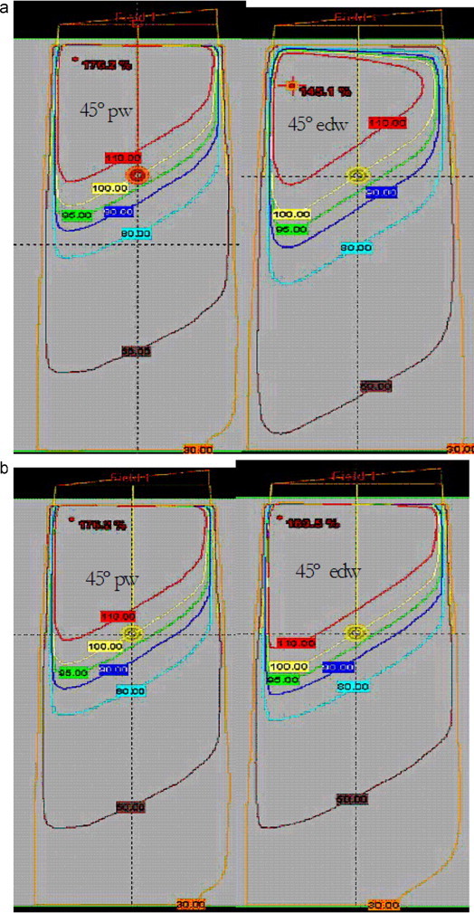
The measured isodose plots for physical and enhanced dynamic wedges were compared for both 6 and 18 MV photon beams. The isodose curve for a 10 cm × 10 cm field size with 15° for 6 MV is shown in Fig. 4a and the one with 45° wedge for 18 MV is shown in Fig. 4b. The figures show that the dose contribution to the ‘toe’ side of the enhanced dynamic wedge is higher. The isodose curve calculated by the treatment planning system for physical and enhanced dynamic wedges of 6 and 18 MV photon fields are shown in Fig. 5a and b. These figures also show an increased dose contribution to the ‘toe’ side of the enhanced dynamic wedge.
Fig. 4.

(a) Measured isodose curve for 15° wedge with 10 cm × 10 cm field size for 6 MV photons (solid line represents EDW and dotted line represents PW). (b) Measured isodose curve for 45° wedge with 10 cm × 10 cm field size for 18 MV photons (solid line represents PW and dotted line represents EDW).
Fig. 5.
TPS generated isodose curve for 45° physical and enhanced dynamic wedges with 10 cm × 10 cm field size for (a) 6 MV photons and (b) 18 MV photons.
4.5. Comparison of profiles of physical and enhanced dynamic wedge fields
The measured profiles of physical and enhanced dynamic wedges for 6 and 18 MV photons at the depth of dmax, 10 cm and 20 cm were compared with the help of OmniPro I’mRT software. The intensity maps obtained for physical and EDWs were compared and the gamma pixel matches were analyzed. The comparison results for 15°, 30°, 45° and 60° wedges for 6 and 18 MV photons are shown in Table 2. Fig. 6a and b shows the comparison profile and match values for 30° wedge with 10 cm × 10 cm field sizes at dmax for 6 and 18 MV photons, respectively. The correlation coefficient is close to 1 for all wedge angles with 6 MV and 18 MV photons. The results show that the profiles obtained for physical and enhanced dynamic wedges at various depths are comparable.
Table 2.
Comparison of intensity maps of physical and enhanced dynamic wedges for 10 cm × 10 cm field size at the depth of dmax, 10 cm and 20 cm for 6 and 18 MV photons.
| Wedge angle | DD |
DTA |
γ ≤ 1 |
DD |
DTA |
γ ≤ 1 |
DD |
DTA |
γ ≤ 1 |
|---|---|---|---|---|---|---|---|---|---|
| dmax | 10 cm | 20 cm | |||||||
| 6 MV photons | |||||||||
| 15° | 2% | 2 mm | 100% | 2% | 2 mm | 100% | 2% | 2 mm | 100% |
| 30° | 3% | 2 mm | 100% | 2% | 2 mm | 100% | 3% | 3 mm | 100% |
| 45° | 3% | 3 mm | 98% | 3% | 3 mm | 98% | 3% | 3 mm | 97.4% |
| 60° | 3% | 3 mm | 96.6% | 3% | 3 mm | 96.7% | 3% | 3 mm | 100% |
| 18 MV photons | |||||||||
| 15° | 2% | 2 mm | 100% | 2% | 2 mm | 100% | 2% | 2 mm | 100% |
| 30° | 2% | 2 mm | 100% | 2% | 2 mm | 100% | 2% | 2 mm | 100% |
| 45° | 2% | 2 mm | 100% | 2% | 2 mm | 100% | 2% | 2 mm | 100% |
| 60° | 3% | 3 mm | 97.6% | 3% | 3 mm | 97.2% | 3% | 3 mm | 100% |
DD: delta dose, DTA: distance to agreement, γ ≤ 1: gamma pixel match.
Fig. 6.

Profile comparison of 30° physical and enhanced dynamic wedges at dmax with 10 cm × 10 cm field size for (a) 6 MV photons and (b) 18 MV photons.
5. Conclusion
In this study, the dosimetric properties of physical and enhanced dynamic wedges for 6 and 18 MV photons were compared. The wedge field output factor increases with field size and wedge angle compared to that of the open field output factor. Hence, the study suggests that the wedge factor measured for a reference field size when used in combination with the open beam output factor for treatment dose calculation may lead to uncertainties in dose estimation. Hence, a separate wedge output factor has to be incorporated in the treatment calculation. The number of monitor units to deliver a particular dose with an EDW field is lower than that of PW field, due to the change in wedge factor. Enhanced dynamic wedges eliminate the beam hardening effect, which is common in physical wedges. The dosimetric characteristics, like profile and isodose of enhanced dynamic wedge, closely match with those of the physical wedge. The use of EDW, eliminates the operator handling of PW and provides the operator with more opportunity to focus on the patient, and reduce setup time between fields for the same patient and between patients. Also, the dose and jaw position control accuracy statistics are displayed on the screen and saved to dynalog files after each clinical EDW treatment. These statistics confirm the precision of treatment delivery.
Conflict of Interest
None declared.
References
- 1.Bentel G.C., Nelson C.E., Noel K.T. 4th ed. Pergamon Press; Elmsford, NY: 1989. Treatment planning and dose calculation in radiation oncology. [Google Scholar]
- 2.12–14. ICRU; Washington, DC: 1976. (Determination of absorbed dose in a patient irradiated by beams of X or gamma rays in radiotherapy procedures. ICRU Ref 24). [Google Scholar]
- 3.Palta J., Daftari I., Suntharalingam N. Field size dependence of wedge factor. Med Phys. 1988;15:624–626. doi: 10.1118/1.596217. [DOI] [PubMed] [Google Scholar]
- 4.Sewchand W., Khan F.M., Williamson J. Variation in depth-dose data between open and wedge fields for 4-MV X-rays. Radiology. 1978;127:789–792. doi: 10.1148/127.3.789. [DOI] [PubMed] [Google Scholar]
- 5.Miften M., Zhu X.R., Takahashi K., Lopez F., Gillin M.T. Implementation and verification of virtual wedge in a three-dimensional radiotherapy planning system. Med Phys. 2000;27:1635–1643. doi: 10.1118/1.599030. [DOI] [PubMed] [Google Scholar]
- 6.Rathee S., Kowk C.B., MacGillivray C., Mirzaei M. Commissioning, clinical implementation and quality assurance of Siemen's Virtual wedge. Med Dosim. 1999;24:145–153. doi: 10.1016/s0958-3947(99)00003-5. [DOI] [PubMed] [Google Scholar]
- 7.Desobry G.E., Waldron T.J., Das I.J. Validation of a new virtual wedge model. Med Phys. 1998;25:71–73. doi: 10.1118/1.598172. [DOI] [PubMed] [Google Scholar]
- 8.Leavitt D.D., Martin M., Moeller J.H., Lee W.L. Dynamic wedge field techniques through computer-controlled motion and dose delivery. Med Phys. 1990;17:87–91. doi: 10.1118/1.596533. [DOI] [PubMed] [Google Scholar]
- 9.Leavitt D.D., Lee W.L., Gafney D.K., Moller J.H., O’Rear J.H. Dosimetric parameters of enhanced dynamic wedge for treatment planning and verification. Med Dosim. 1997;22:177–183. doi: 10.1016/s0958-3947(97)00028-9. [DOI] [PubMed] [Google Scholar]
- 10.Beavis A.W., Weston S.J., Whitton V.J. Implementation of Varian EDW into a commercial RTP system. Phys Med Biol. 1996;41:1691–1704. doi: 10.1088/0031-9155/41/9/009. [DOI] [PubMed] [Google Scholar]
- 11.Liu H.H., McCullough E.C., Mackie T.R. Calculating dose distributions and wedge factors for photon treatment fields with dynamic wedges based on a convolution/superposition method. Med Phys. 1998;25:56–63. doi: 10.1118/1.598173. [DOI] [PubMed] [Google Scholar]
- 12.krzysztof Chełmiński, Wojciech Bulski, Joanna Rostkowska, Małgorzata Kania Dynamic wedges – dosimetry and quality control. Rep Pract Oncol Radiother. 2006;11(2):67–75. doi: 10.1016/j.rpor.2010.02.003. [DOI] [PMC free article] [PubMed] [Google Scholar]
- 13.Chełmiński K., Bulski W., Georg D. Energy dependence of radiochromic dosimetry films for use in radiotherapy verification. Dept Pract Oncol Radiother. 2010;15(2):40–46. doi: 10.1016/j.rpor.2010.02.003. [DOI] [PMC free article] [PubMed] [Google Scholar]
- 14.Marzena Janiszewska, Grzegorz Nowakowski Dosimetric verification of fields. Rep Pract Oncol Radiother. 2003;8(4):139–152. [Google Scholar]
- 15.Prado K.L., Kirsner S.M., Kudchadker R.J., Steadham R.E., Lane R.G. Enhanced dynamic wedge factors at off-axis points in asymmetric fields. J Appl Clin Med Phys. 2003;4:75–84. doi: 10.1120/jacmp.v4i1.2544. [DOI] [PMC free article] [PubMed] [Google Scholar]
- 16.Gibbons J.P. Calculation of enhanced dynamic wedge factors for symmetric and asymmetric photon fields. Med Phys. 1998;25:1411–1418. doi: 10.1118/1.598313. [DOI] [PubMed] [Google Scholar]
- 17.Klein E.E., Low D.A., Meigooni A.S., Purdy J.A. Dosimetry and clinical implementation of dynamic wedge. Int J Radiat Biol Phys. 1995;31:583–592. doi: 10.1016/0360-3016(94)00369-V. [DOI] [PubMed] [Google Scholar]
- 18.Zhu T.C., Ding L., Liu C.R., Palta J.R., Simon W.E., Shi J. Performance evaluation of a diode array for enhanced dynamic wedge dosimetry. Med Phys. 1997;24:1173–1180. doi: 10.1118/1.598019. [DOI] [PubMed] [Google Scholar]
- 19.Alaei P., Higgins P.D. Performance evaluation and quality assurance of Varian enhanced dynamic wedges. J Appl Clin Med Phys. 2006;7:14–20. doi: 10.1120/jacmp.v7i1.2170. [DOI] [PMC free article] [PubMed] [Google Scholar]
- 20.Zhu X.R., Gillin M.T., Jursinic P.A., Lopez F., Grimm D.F., Rownd J.J. Comparison of dosimetric characteristics of Siemens virtual and physical wedges. Med Phys. 2000;27:2267–2277. doi: 10.1118/1.1312813. [DOI] [PubMed] [Google Scholar]
- 21.IEC report 796 (1989).
- 22.I’mRT MatriXX user manual Perliminary version. Scanditronix, Wellhofer, Germany.