

Abstract
Aim
To compare the measured and calculated individual and composite field planar dose distribution of Intensity Modulated Radiotherapy plans.
Materials and methods
The measurements were performed in Clinac DHX linear accelerator with 6 MV photons using Matrixx device and a solid water phantom. The 20 brain tumor patients were selected for this study. The IMRT plan was carried out for all the patients using Eclipse treatment planning system. The verification plan was produced for every original plan using CT scan of Matrixx embedded in the phantom. Every verification field was measured by the Matrixx. The TPS calculated and measured dose distributions were compared for individual and composite fields.
Results and discussion
The percentage of gamma pixel match for the dose distribution patterns were evaluated using gamma histogram. The gamma pixel match was 95–98% for 41 fields (39%) and 98% for 59 fields (61%) with individual fields. The percentage of gamma pixel match was 95–98% for 5 patients and 98% for other 12 patients with composite fields. Three patients showed a gamma pixel match of less than 95%. The comparison of percentage gamma pixel match for individual and composite fields showed more than 2.5% variation for 6 patients, more than 1% variation for 4 patients, while the remaining 10 patients showed less than 1% variation.
Conclusion
The individual and composite field measurements showed good agreement with TPS calculated dose distribution for the studied patients. The measurement and data analysis for individual fields is a time consuming process, the composite field analysis may be sufficient enough for smaller field dose distribution analysis with array detectors.
Keywords: IMRT, I’matriXX, TPS, Gamma pixel
1. Background
Intensity modulated fields have the potential to deliver optimum dose distributions which results in a greater dose uniformity in the target and lower doses to the neighboring critical organs and normal healthy structures as compared to conventional external beams employing wedges and cerroband blocks.1 The clinical implementation of Intensity Modulated Radiotherapy (IMRT) requires special commissioning procedures including machine and patient-related routine quality assurance (QA).2–8 The IMRT has made a considerable impact on both clinical and physical aspects of radiotherapy. The IMRT patient specific QA procedures have been emphasized and the clinical requirements for IMRT implementation have been the driving force behind many medical physics research activities. A major difficulty with designing IMRT QA procedures for treatment delivery units, treatment planning system (TPS) and patient-specific QA was that the likely failures for this new treatment technique were not known. On the other hand, traditionally used methods and equipment designed for dose verification in uniform intensity beams were becoming obsolete. For example, point dose measurements were replaced or supplemented with two-dimensional measurements.9,10 Another example is monitor unit (MU) verification procedures, as empirical methods for dose calculation11 cannot be applied or extended to IMRT in any straightforward manner. Due to the lack of efficient tools for patient-specific QA, routine dosimetric methods are still commonly used to verify IMRT treatment plans.12 The European Society for Therapeutic Radiation Oncology (ESTRO) have started the QUASIMODO (QUality ASsurance of Intensity MODulated radiation Oncology) network between fifteen European centers.13 They suggest that the verification of a composite plan is of utmost importance for the actual patient treatment. Agazaryan et al.14 compared the measured single field and composite field IMRT planar dose with TPS computed values.
2. Aim
The patient specific IMRT QA of brain tumor patients were carried out using a 2-D ion chamber array detector. The planar dose distribution measured by the array detector for individual and composite field were compared with the TPS calculated dose distribution.
3. Materials and methods
The Matrixx (Matrixx, IBA Dosimetry GmBH, Schwarzenbruck, Germany) device consists of 1020 vented ion chamber array detectors, arranged in 32 × 32 grid. Eeach chamber volume is 0.08 cm3 with the height of 5 mm and diameter of 4.5 mm. The detecting system can measure the dose distribution for the dose rate ranging from 0.1 Gy/min to 5 Gy/min.15 The bias voltage required for the Matrixx system is 500 ± 30 V. The equivalent absorber thickness on the front side of the matrix is 3.6 mm. The maximum field of view is 24 × 24 cm2. Before the measurement, the device requires 15 min of warm-up time. The device runs with two separate counters to avoid dead time, the minimum sampling period is 20 ms. The Matrixx device can be directly connected to PC via standard ethernet interface to acquire the measured charge.
The measurements were performed on Clinac DHX linear accelerator with 6 MV photon beams using Matrixx device and a RW3 solid water phantom. The Millennium multileaf collimator (MLC) is an accessory attached to the treatment head below the secondary jaws as tertiary collimator. The Millennium MLC contains 120 leaves designed with 5 mm leaf width projected at isocenter the middle 20 cm of the treatment field and 10 mm leaf width projected over the peripheral 10 cm on each side of the treatment field. The leaf movements are controlled by the stepper motors through MLC controller workstation (Millennium MLC user guide, P/N 100011548). The MLC is capable of producing irregular shaped fields and dynamic motion. It is possible to achieve dose dynamic and arc dynamic IMRT treatments with dynamic MLC motion. The Matrixx device with a 5 cm solid water phantom positioned above and below was scanned with 2 mm CT slice thickness. The CT scan data was imported to TPS for 3-D reconstruction and planning. Twenty brain tumor patients were selected for this study. The IMRT treatment plan was carried out for all the patients using the sliding window technique with Eclipse treatment planning system (Varian Medical systems, USA). The 5 equally spaced beam angles were selected for each plan at an interval of 72° for all the brain tumor patients. The Anistrophic analytical algorithm (AAA) was used with the calculation grid size of 2.5 mm for dose computation. The IMRT optimization was carried out using Dose Volume Optimizer (DVO) algorithm within the Eclipse treatment planning system. In order to verify an IMRT plan a verification plan with the gantry and collimator angles set at 0 degrees was produced for every original plan using CT scan data of Matrixx device. The CT data of the measurement system was used to estimate the dose distribution at depth for these verification plans. The verification plan was exported to the detector system with the detector plane positioned at isocenter. The gantry and collimator angles were set at 0 degrees. The central beam was made perpendicular to the Matrixx measurement level at the center of the measurement area. The Matrixx setup is shown in Fig. 1. Every verification field was exported to the accelerator console and the same was delivered and measured by the Matrixx device. The TPS calculated individual and composite field dose distributions were transferred to OmniPro IMRT software for comparison. The measured Matrixx signal for each field was post-processed with linear interpolation using 0.2 mm grid. The same grid value was selected for TPS calculated dose distribution pattern for comparison. The measured individual dose distribution was compared with TPS calculated dose distribution and the percentages of pixel match values were evaluated using gamma histogram.
Fig. 1.

Matrixx along with slap phantom.
4. Results and discussion
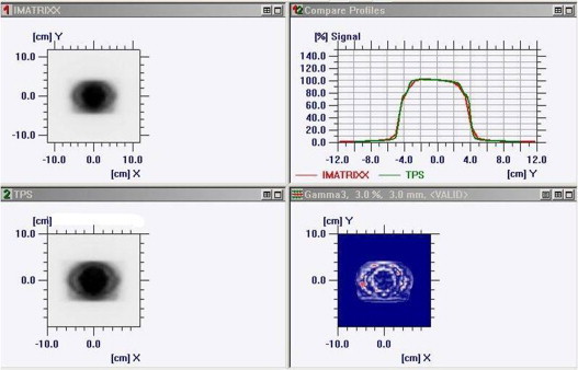
The measured and calculated dose distribution patterns were imported to OmniPro IMRT software workspace for analysis in data set 1 and data set 2. The gamma criteria were set at 3% dose difference and 3 mm distance-to-agreement (DTA) with γ ≤ 1. Fig. 2 shows the comparison of measured and calculated planar dose distribution for an individual field. The compared profile along the X and Y directions for an individual field is shown in Fig. 3a and b. Fig. 4 shows the compared isodose distribution of an individual field. The percentage of gamma pixel match for an individual field was obtained. The gamma pixel match was less than 95% for 5 fields. The gamma pixel match was between 95 and 98% for 41 fields (39%) and 59 fields (61%) have shown the gamma pixel match of more than 98%.
Fig. 2.

Comparison of measured and calculated dose distribution for individual field.
Fig. 3.
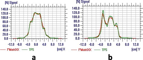
(a) and (b) Compared profile along the X and Y directions for individual field.
Fig. 4.

Compared isodose distribution for individual field.
Similarly, the measured composite dose distribution was compared with TPS calculated dose distribution and the percentages of pixel match values were evaluated using gamma histogram. Fig. 5 shows the comparison of measured and calculated planar dose distribution for a composite field. The compared profile along the X and Y directions for cumulative field is shown in Fig. 6a and b. Fig. 7 shows a typical compared isodose distribution for a composite field. The percentage of gamma pixel match was 95–98% for 5 patients and 12 patients showed the gamma pixel match of more than 98% for a composite field. The gamma pixel match of less than 95% was noticed only for 3 patients. The root mean square (RMS) values were calculated for an individual field gamma pixel match of each patient. The gamma pixel match of 95–98% was shown for 10 patients and 10 patients were shown the gamma pixel match of more than 98%. Fig. 8 shows the comparison of percentage gamma pixel match values for individual and composite fields. Six patients were noticed to show more than 2.5% variation between individual and composite field analysis and 4 patients have shown more than 1% variation between the individual and composite field analysis. The remaining 10 patients showed less than 1% variation between the individual and composite field analysis. The AAPM TG119 recommends that the percentage of the gamma criteria should be more than 88% for an individual field analysis and 93% for composite fields.16 The results in our study are in good agreement with the AAPM TG119 recommendation. It was observed that for smaller targets to be treated, like brain, the composite field analyses are not much different from an individual analysis. In case of large targets, like Head and Neck, the magnitude of deviation between individual and composite fields was also analyzed for 3 head and neck patients. The results of percentage of points passing the gamma criteria of 3%/3 mm for composite and individual plan analysis is shown in Table 1. The gamma pixel match varied from 83.6% to 99.7% for individual fields and 90–92% for composite fields.
Fig. 5.
Comparison of measured and calculated dose distribution for composite field.
Fig. 6.

(a) and (b) Compared profile along the X and Y directions for composite field.
Fig. 7.

Compared isodose distribution for composite field.
Fig. 8.

Comparison of percentage gamma pixel match values for individual and composite fields.
Table 1.
Percentage of points passing the gamma criteria of 3%/3 mm for composite and individual plan analysis for head and neck patients.
| Field (Gantry angle) | Percentage of points passing the gamma criteria of 3%/3 mm |
||
|---|---|---|---|
| Patient 1 | Patient 2 | Patient 3 | |
| 0° | 92.29% | 99.21% | 92.17% |
| 40° | 97.14% | 96.59% | 94.05% |
| 80° | 99.67% | 93.49% | 99.20% |
| 120° | 83.61% | 97.05% | 98.33% |
| 160° | 98.39% | 91.87% | 91.80% |
| 280° | 96.50% | 95.70% | 94.57% |
| 320° | 91.74% | 99.34% | 99.38% |
| 200° | 96.18% | 98.53% | 94.64% |
| 240° | 94.06% | 98.22% | 99.20% |
| Composite field | 91.69% | 91.51% | 90.70% |
5. Conclusion
The IMRT plans were analyzed by comparing measured and calculated dose distributions for both composite and individual fields. Both individual and composite field measurements showed good agreement with TPS calculated dose distribution for the studied patients. Although the composite field analysis, the cumulative dose distribution, the magnitude of deviation with some beam angles could be suppressed when combined with the other fields. The individual field delivery permits the beam's delivery to be analyzed in detail but does not assure that the beams combine appropriately. Hence, for the smaller tumors, like brain, the composite field analysis are not much different from individual analysis, whereas for large tumors, the magnitude of deviation between individual and composite field analysis may be higher due to doses added together from the larger area. In case of large field composite analysis, it may not be possible to predict by which field the maximum deviation in dose delivery occurs. As the measurement and data analysis for individual fields are a time consuming process, the composite field analysis may be sufficient enough for smaller field dose distribution analysis with array detectors.
Conflict of interest
None declared.
Footnotes
Registered under Karnataka Societies Registration Act 1960, Regn. No. S475/79-80 Donations to this Institute are exempt from income Tax u/s 80G of IT Act, 1961 and under Sec. 35 (i) & (ii) of IT Act. 1961. Email: root@kidwai.kar.nic.in.
References
- 1.Kallman P., Lind B., Eklof A., Brahme A. Shaping of arbitrary dose distribution by dynamic multileaf collimation. Phys Med Biol. 1998;33:1291–1300. doi: 10.1088/0031-9155/33/11/007. [DOI] [PubMed] [Google Scholar]
- 2.Bayouth J.E., Wendt D., Morrill S.M. MLC quality assurance technique for IMRT applications. Med Phys. 2003;30(5):743–750. doi: 10.1118/1.1564091. [DOI] [PubMed] [Google Scholar]
- 3.Chui C.-S., Spirou S., LoSasso T. Testing of dynamic multileaf collimation. Med Phys. 1996;23(5):635–641. doi: 10.1118/1.597699. [DOI] [PubMed] [Google Scholar]
- 4.LoSasso T., Chui C.-S., Ling C. Comprehensive quality assurance for the delivery of intensity modulated radiotherapy with a multileaf collimator used in the dynamic mode. Med Phys. 2001;28(11):2209–2219. doi: 10.1118/1.1410123. [DOI] [PubMed] [Google Scholar]
- 5.Gopi S., Ganesan S., Aruna P., Bouchaib R., Supe S.S. Influence of photon beam energy on IMRT plan quality for radiotherapy of prostate cancer. Rep Pract Oncol Radiother. 2009;14(1):18–31. [Google Scholar]
- 6.Anup Kumar B., Suresh Chander S., Bhupendra R., Arvind S. Study of 2D ion chamber array for angular response and QA of dynamic MLC and pretreatment IMRT plans. Rep Pract Oncol Radiother. 2009;14(3):89–94. [Google Scholar]
- 7.Janusz W., Tomasz M., Karolina M., Barbara D. The gamma evaluation method as a routine QA procedure of IMRT. Rep Pract Oncol Radiother. 2009;14(5):162–168. [Google Scholar]
- 8.Slosarek K., Szlag M., Bekman B., Grzadziel A. EPID in vivo dosimetry in RapidArc technique. Rep Pract Oncol Radiother. 2010;15(1):8–14. doi: 10.1016/j.rpor.2010.01.003. [DOI] [PMC free article] [PubMed] [Google Scholar]
- 9.Stock M., Kroupa B., Georg D. Interpretation and evaluation of the gamma index and the gamma index angle for the verification of IMRT hybrid plans. Phys Med Biol. 2005;50:399–411. doi: 10.1088/0031-9155/50/3/001. [DOI] [PubMed] [Google Scholar]
- 10.Wiezorek T., BanzN, SchwedasM, Scheithauer M., Salz H., Georg Dand Wendt T.G. Dosimetric quality assurance for intensity-modulated radiotherapy feasibility study for a filmless approach. Strahlenther Onkol. 2005;181:468–474. doi: 10.1007/s00066-005-1381-z. [DOI] [PubMed] [Google Scholar]
- 11.Dutreix A, Svensson H, Bjärngard BE, Bridier A, Mijnheer A, Shaw J. Monitor unit calculation for high energy photon beams. ESTRO Booklet No. 3.1997.
- 12.Sukumar P., Padmanaban S., Jeevanandam P., Syam Kumar S.A., Nagarajan V. A study on dosimetric properties of electronic portal imaging device and its use as a quality assurance tool in volumetric modulated arc therapy. Rep Pract Oncol Radiother. 2011;16(6):248–255. doi: 10.1016/j.rpor.2011.08.001. [DOI] [PMC free article] [PubMed] [Google Scholar]
- 13.Alber M, et al. Guidelines for the verification of IMRT. ESTRO Booklet no.9, Brussels, Belgium; 2008.
- 14.Nzhde Agazaryan, Solberg Timothy D., DeMarco John J. Patient specific quality assurance for the delivery of intensity modulated radiotherapy. J Appl Clinc Med Phys. 2003;4(1):40–50. doi: 10.1120/jacmp.v4i1.2540. [DOI] [PMC free article] [PubMed] [Google Scholar]
- 15.I’mRT MatriXX user manual, Scanditronix, Wellhofer; 2006.
- 16.Ezzell G.A., Burmeister J.W., Dogan N. IMRT commissioning: multiple institution planning and dosimetry comparisons, a report from AAPM Task group 119. Med Phys. 2009;36(11):5359–5373. doi: 10.1118/1.3238104. [DOI] [PubMed] [Google Scholar]