

Abstract
Multifocal multiphoton microscopy (MMM) has recently become an important tool in biomedicine for performing three-dimensional fast fluorescence imaging. Using various beamsplitting techniques, MMM splits the near-infrared laser beam into multiple beamlets and produces a multifocal array on the sample for parallel multiphoton excitation and then records fluorescence signal from all foci simultaneously with an area array detector, which significantly improves the imaging speed of multiphoton microscopy and allows for high efficiency in use of the excitation light. In this paper, we discuss the features of several MMM setups using different beamsplitting devices, including a Nipkow spinning disk, a microlens array, a set of beamsplitting mirrors, or a diffractive optical element (DOE). In particular, we present our recent work on the development of an MMM using a spatial light modulator (SLM).
Keywords: Multifocal multiphoton microscopy (MMM), microlens array, beamsplitter, diffractive optical element (DOE), spatial light modulator (SLM)
1. Introduction
Multiphoton microscopy (MPM) is an important tool in biomedicine for performing 3D fluorescence imaging.1–3 Compared with confocal laser scanning microscopy (CLSM), MPM has many advantages. MPM usually employs near-infrared (NIR) laser as excitation source, which allows for higher penetration depth in scattering tissue than confocal microscopes that usually use visible lasers for one-photon excitation. In addition, the nonlinear absorption of multiple photons simultaneously confines its excitation volume to the focal region, which provides inherent optical sectioning and causes less photobleaching and photodamage to the out-of-focus sample. However, MPM is dependent on the scanning of a single excitation spot across the sample pixel-by-pixel, which is similar to CLSM, resulting in low imaging speed and enormous waste of excitation light power.
Multifocal multiphoton microscopy (MMM) has been introduced as a fast and efficient imaging modality in the late 20th century.4,5 It shares almost all the advantages of multiphoton microscopy. MMM employs a beamsplitting device to produce a multi-focal array on the sample for parallel multiphoton excitation and uses an area array detector, e.g., a CCD camera, to record the fluorescence from the multiple foci, therefore fast imaging and high efficiency in using the laser power can be achieved.
In conventional MPM, only one focused excitation light spot is scanned across the sample. Due to possible photodamage to the sample, a very small percentage of the excitation light from the ultrafast femtosecond laser is used. The idea behind MMM is to spread the laser output across the sample in multiple foci so that more power from the light source can be used than that in the single point scanning MPM. Typically, splitting the incident laser beam into M × N beamlets can give rise to about M × N fold increase in imaging speed.
Using various beamsplitting devices, such as a Nipkow spinning disk, a microlens array, a set of beamsplitting mirrors, or a diffractive optical element (DOE), MMM can be implemented in different modalities. We discuss the features of several MMM setups, and present our recent work on the development of an MMM system using a spatial light modulator.
2. MMMs with Various Beamsplitting Techniques
2.1. MMM based on microlens array
In 1998, Bewersdorf et al. reported the implementation of the first MMM setup using a Nipkow-type arranged focal pattern,4 in which the microlenses were arranged in a hexagonal pattern such that the wavefront of the illuminating beam is split and focused to form an array of approximately 5 × 5 focus array to scan the sample (Fig. 1). It achieved a scanning rate of up to 1000 frames per second (fps). However, the effective imaging speed was at video rate because it was limited by the frame rate of the CCD camera and the fluorescence signal intensity.
Fig. 1.

Schematic of the MMM for real-time, direct-view nonlinear microscopy: L’s, lenses; ML, microlens disk; M, optional mirror; F, short-pass filter; DM, dichroic mirror. Inset, the rotating microlens array.4
In the same year, another MMM setup using a rectangular microlens arrangement was implemented by Buist et al. (Fig. 2).5 Scanning was accomplished by rapidly moving the focus array in a Lissajous pattern with an x–y galvanometric mirror. Proper adjustment of the frequency and amplitude of the scanning allowed nearly uniform illumination at the video rate.
Fig. 2.

Schematic layout (not to scale) of the MMM optical setup based on microlens array. The marginal rays for one of the microlenses are drawn.5
In these two setups, the microlenses are illuminated by an expanded and collimated laser beam to create multiple beamlets. Due to the expansion of the Gaussian-shape laser beam, the beamlet’s average intensity is not necessarily identical. Moreover, much of the laser light is discarded. For example, the Nipkow-disk-based MMM has an ~50% decrease of the intensity of the foci at the edge of the field of view (FOV) than that of the center4; while the rectangular microlens-based MMM uses only ~25% of the laser output.5 To avoid wasting large amount of laser power, sophisticated beam shaping optics may prove useful, which can convert Gaussian beams into homogeneous beams with flat top wavefront.6
Another issue related to those setups is to prevent unwanted optical (out-of-focus) excitation crosstalk between the beamlets. Significant crosstalk can be reduced by using the combination of a microlens array and a pinhole array.7,8 A more effective solution to interfocal crosstalk is time multiplexing,9,10 which solves this problem by introducing a temporal delay between the beamlets to ensure that light pulses of neighboring foci pass the focal region at different time points.
There are further developments in the microlens array-based MMM. Egner et al. applied the idea of MMM to 4Pi-microscopy for higher axial resolution as well as fast imaging, in which a square array of microlenses was used.11,12 Qu et al. developed a simultaneous time- and spectrum-resolved multi-focal multiphoton microscopy (STSR-MMM) by combining a microlens array, a prism, and a streak camera.13,14
2.2. MMM based on cascaded beam splitters
Another approach for MMM is to split the beam intensity equally by an etalon15 or a cascade of beamsplitters16,17 instead of dividing the expanded laser beam across its profile. With the setup shown in Fig. 3,17 a 8 × 8 focus array is produced. The overall transmission of the beam splitter is 91%, which is much higher than that for the microlens scheme. The advantage of using such an etalon is that the laser beam profile is maintained for each beamlet, and due to different optical path lengths, neighboring foci are temporally decorrelated. Therefore, the average beamlet intensity is identical and no crosstalk exists between different foci. Additionally, it has been shown that such a setup is capable of “scanless” imaging at small interfocal distance.18
Fig. 3.
Schematic of a multibeam two-photon microscope based on a cascaded beamsplitter.17
However, this setup has strict requirements for the splitting ratio of the beamsplitters and the tilting angle of the mirrors. If the ratio between the reflected and transmitted light is not exactly 50/50, chessboard pattern will be produced at the edges of the subfields in the image. The tilting and parallelization of the beamsplitters must be handled with particular care in order to obtain equidistant foci with each beamlet centered on the objective entrance pupil.17 In order to achieve the best possible resolution, the objective entrance pupil still needs to be uniformly illuminated.
2.3. MMM based on DOE
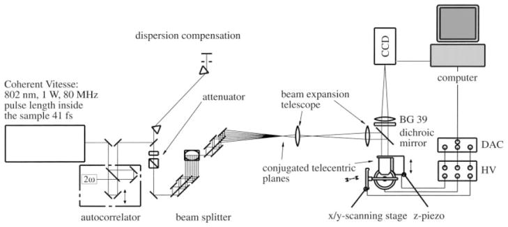
In 2003, Sacconi et al. reported an MMM setup using a miniature, low cost DOE along with galvo scanners (see Fig. 4).19 The DOE produced an array of 4 × 4 focal points with a diffraction efficiency of 75% and uniformity in focal intensity within 1%. An imaging speed of 10 fps was obtained with this setup.
Fig. 4.
Experimental setup of MMM that is based on a DOE. L1, L2, telescopic lens pair (2 × magnification) that pivots the grid on the first galvo scanner (GX). L3, L4, second telescopic lens pair that pivots the grid on the second galvo scanner (GY). L5 and tube lens TL, telescopic lens pair (4 × magnification) that pivots the grid on the back focal plane of the objective. DM, BF, dichroic mirror, and blocking filter, respectively.19
In a similar DOE-based MMM system (as shown in Fig. 5) reported by Jureller et al., a 10 × 10 hexagonal focus array was produced and scanned by a white noise-driven galvanometer.20 Imaging speed of this so-called stochastic scanning MMM was 1000-fold faster than a conventional single beam raster scanning multiphoton microscope. Moreover, sampling of this system was much more uniform and the acquired image did not display edge sampling artifacts by stochastic scanning compared with raster scanning, which showed that it was a suitable mechanism for multifocal scanning in MMM.
Fig. 5.
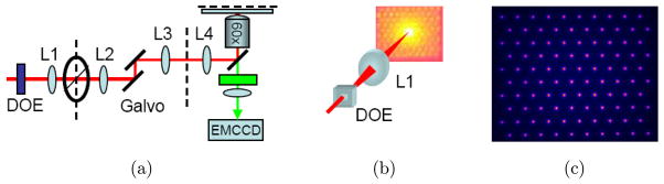
(a) SS-MMM setup, (b) DOE generated 10 × 10 hexagonal multifocal array. The smaller image is the actual array after L1, (c) False color two-photon fluorescence image of the multifocal array in a solution of Rhodamine 6G at the sample plane.20
3. MMM Based on SLM
All the above-mentioned MMM setups use fixed beamsplitting optics, and thus FOV of the system and imaging area of interest are usually unchangeable. When the entire FOV of an MMM is scanned, the imaging rate increases with the number of beamlets. However, with the increase of the number of beamlets, the power of each beamlet decreases, resulting in a low signal to noise ratio. Therefore, a compromise should be reached between the adjustable flexibility and the focal intensity. In some applications, however, only a small area of the FOV contains the features that must be rapidly imaged with high resolution. In those cases, a small number of beamlets can be used to scan the FOV with slow speed and low resolution, and then the area(s) of interest can be scanned rapidly with fast speed and high resolution. An SLM can be used to realize this addressable multifocal imaging concept and it has been employed in a scanless microscopy to distribute the illumination light dynamically into multiple areas of interest.21,22
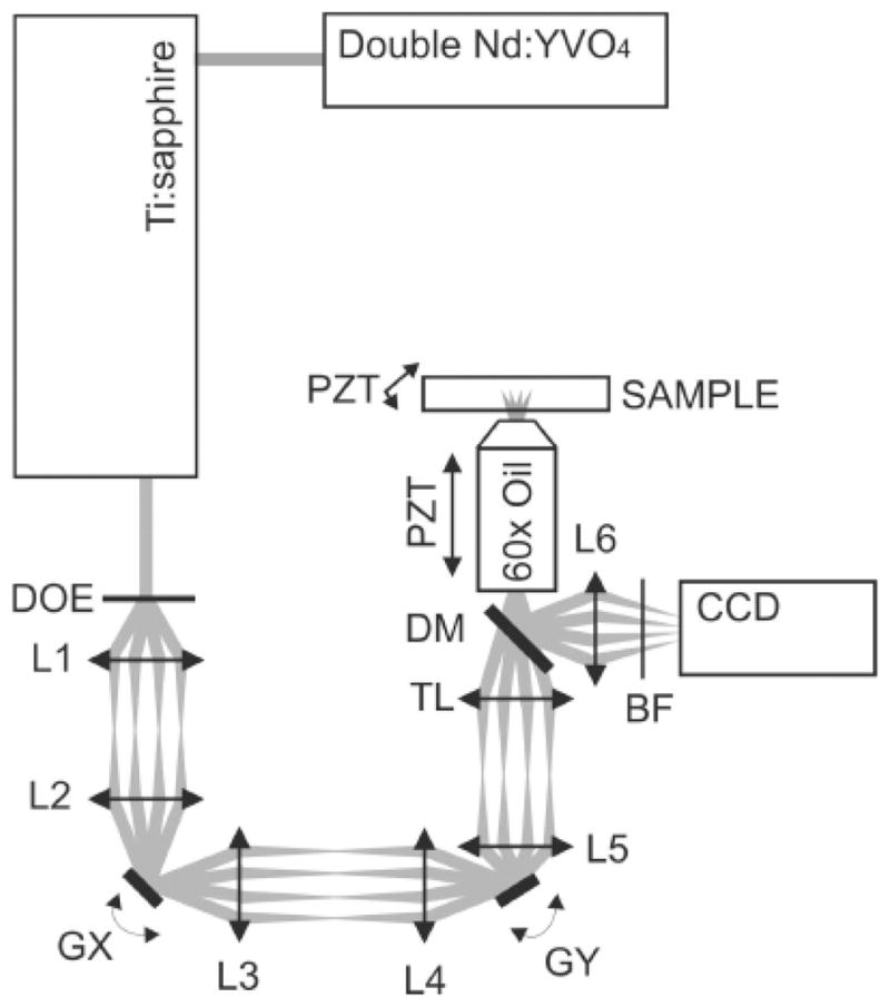
We have reported the development of an addressable multiregional MMM (AM-MMM) that comprises of an SLM and galvo scanners to produce multiple focus arrays. Our system is shown in Fig. 6.23 The SLM is based on reflective liquid crystal on silicon, which modulates an incident light beam spatially in phase to generate dynamically arbitrary patterns with computer-generated phase-only holograms without any change to the system hardware. By altering the phase image, the orientation of the beamlets can be changed, and thus multibeam scanning can be achieved. However, the transfer rate of the phase image for a commercially available SLM is too low (less than 100 Hz) to achieve high-speed imaging. Consequently, we should use the SLM to achieve only beamsplitting (without scanning), and use a pair of galvo scanners to realize the scanning of the focus array. For this purpose, the SLM can be modeled as a DOE coupled with a reflecting mirror: The DOE feature allows the SLM to split the incident beam into multiple beamlets, and the mirror feature permits the SLM to reflect the incident beam with various incident angles into the conjugated angle, thus achieving beam scanning. The pattern of the addressable arrays is sequentially or stochastically scanned across a sample’s multiple areas of interest by a two-mirror galvo scanner driven by a line-by-line or a normalized white noise waveform.
Fig. 6.

Schematic of the AM-MMM based on an SLM and galvo scanners. The galvo scanners (GS) comprise x- and y-scanners on the front focal plane of a 4f system comprising L1 and L2. The SLM on the back focal plane of L2 modulates the input fs beam to generate multifocal arrays through a Fourier lens (L3) on the front focal plane of the tube lens (L4); the zero-order light is blocked by a blocker. The polarization of the fs beam is tuned by a λ/2 waveplate. Laser: a model-locked laser that generates an fs beam; M1 to 5: gold film mirrors; Camera: an EM-CCD.23
Figure 7 shows a few arbitrary two-photon fluorescence array patterns formed within a sheet of Rhodamine 6G solution, which is excited by 10 × 10, 20 × 20, and 30 × 30 of laser point array respectively. With the 30 × 30 focus array, auto-fluorescence image of fresh pollen is obtained. Because only the first order of diffraction is used, the unwanted zero order created by the SLM is blocked by a spatial filter.
Fig. 7.
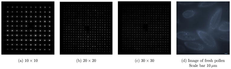
(a)–(c) are the arbitrary required focus array produced by an SLM, (d) is the autofluorescence image of fresh pollen obtained using the 30 × 30 focus array.
One advantage of this AM-MMM system is that its FOV can be changed easily by changing the density or the distance of focus array. The first row in Fig. 8 shows a 10 × 10 and a 30 × 30 focus array obtained from a very thin layer of Rhodamine 6G solution. The second row is the AM-MMM images of 1 μm fluorescent beads with FOVs of 210 × 210 μm2 and 140 × 140 μm2, corresponding to the focus array on the first row. Another advantage of the AM-MMM is that it can perform multiregional and addressable imaging. Figure 9 shows the addressable focus array of Rhodamine 6G solution. From the left four images (a)–(d), we can see that the focus arrays are generated multiregionally with required shapes and densities. (e) is the image of the sarcomere structure in three adult cardiomyocytes stained for α-actinin coming from the pattern of three focus arrays (d) with FOV = 200 × 200 μm2.
Fig. 8.

Two-photon fluorescence images of a coverglass homogeneously coated with a thin layer (approximately 100 nm) of Rhodamine 6G solution using a 30 × 30 focus array with an interfocal distance of 7 μm (a) and a 10 × 10 focus array with an interfocal distance of 14 μm (b). The center red circle in (a) and (b) cannot be illuminated due to blocking the zero-order light with a zero-order filter. Images (c) and (d) are the two-photon images of fluorescent beads with diameter of 1 μm and exposure time of 1 s. The FOV of image (c) is 210 × 210 μm2. The area within the red rectangle in image (d) is 140 × 140 μm2. The area outside the red rectangle is not illuminated, and photon damage is effectively avoided. (Scale bar = 10 μm).
Fig. 9.
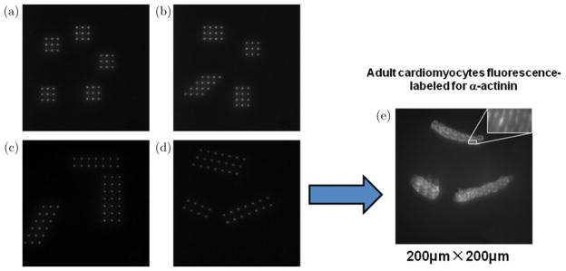
(a)–(d) The addressable focus array of Rhodamine solution with arbitrary shapes and densities; (e) Image of the sarcomere structure in three adult cardiomyocytes stained for α-actinin, which is amplified and shown in the insert image. FOV = 200 × 200 μm2.
4. Conclusion
MMM is capable of high speed multiphoton fluorescence imaging. It utilizes light output from an ultrafast laser more efficiently and causes less photo-damage to samples. Several MMM setups that use various beamsplitting techniques have been developed during the past 14 years. However these MMM systems either do not have uniform focus array (e.g., the MMMs based on Nipkow spinning disk or microlens array) or are not flexible in the shape of the array (e.g., the MMMs based on beamsplitters or DOE). We present a flexible and versatile MMM method (AM-MMM), which allows for high speed and addressable multiphoton fluorescence imaging. It can produce specifically required focus array, zoom in the FOV, and perform multiregional addressable imaging.
In the future work, the imaging speed, flexibility, and performance of AM-MMM will be further improved by using AODs and refining the design of SLM phase patterns. The AM-MMM system can be easily adapted to combine with SHG, THG, and CARS microscopic imaging mechanisms. In addition, we are expecting more biomedical applications for AM-MMM.
Acknowledgments
This work has been partially supported by NIH (SC COBRE P20RR021949 and Career Award 1k25hl088262-01), NSF (MRI CBET-0923311 and SC EPSCoR RII EPS-0903795 through SC GEAR program), The National Natural Science Foundation of China (31171372, 61078067), Guangdong Province Science and Technology Project (2010B060300002), Shenzhen University Application Technology Development Project (201136, CXB201104220021A, JC201005250032A, 200854), and the Fundamental Research Funds for the Central Universities (K50510050006).
References
- 1.Denk W, Strickler JH, Webb WW. 2-photon laser scanning fluorescence microscopy. Science. 1990;248(4951):73. doi: 10.1126/science.2321027. [DOI] [PubMed] [Google Scholar]
- 2.Centonze VE, White JG. Multiphoton excitation provides optical sections from deeper within scattering specimens than confocal imaging. Biophys J. 1998;75(4):2015. doi: 10.1016/S0006-3495(98)77643-X. [DOI] [PMC free article] [PubMed] [Google Scholar]
- 3.Lakowicz JR. Principles of fluorescence spectroscopy. 3. Springer Science and Business Media, LLC; New York: 2006. [Google Scholar]
- 4.Bewersdorf J, Pick R, Hell SW. Multifocal multiphoton microscopy. Opt Lett. 1998;23(9):655. doi: 10.1364/ol.23.000655. [DOI] [PubMed] [Google Scholar]
- 5.Buist AH, Muller M, Squier J, et al. Real time two-photon absorption microscopy using multipoint excitation. J Microsc. 1998;192(Pt 2):217. [Google Scholar]
- 6.Shafer D. Gaussian to flat-top intensity distribution lens. Opt Laser Technol. 1982;14:159. [Google Scholar]
- 7.Fujita K, Nakamura O, Kaneko T, et al. Confocal multipoint multiphoton excitation microscope with microlens and pinhole arrays. Opt Commun. 2000;174:7. [Google Scholar]
- 8.Egner A, Andresen V, Hell SW. Comparison of the axial resolution of practical Nipkow-disk confocal fluorescence microscopy with that of multifocal multiphoton microscopy: Theory and experiment. J Microsc. 2002;206(Pt 1):24. doi: 10.1046/j.1365-2818.2002.01001.x. [DOI] [PubMed] [Google Scholar]
- 9.Egner A, Hell SW. Time multiplexing and parallelization in multifocal multiphoton microscopy. J Opt Soc Amer A. 2000;17(7):1192. doi: 10.1364/josaa.17.001192. [DOI] [PubMed] [Google Scholar]
- 10.Andresen V, Egner A, Hell SW. Time-multiplexed multifocal multiphoton microscope. Opt Lett. 2001;26:75. doi: 10.1364/ol.26.000075. [DOI] [PubMed] [Google Scholar]
- 11.Egner A, Jakobs S, Hell SW. Fast 100-nm resolution 3D microscope reveals structural plasticity of mitochondria in live yeast. Proc Natl Acad Sci USA. 2002;99:3370. doi: 10.1073/pnas.052545099. [DOI] [PMC free article] [PubMed] [Google Scholar]
- 12.Egner A, Verrier S, Goroshkov A, Söling HD, Hell SW. 4 Pi microscopy of the Golgi apparatus in live mammalian cells. J Struct Biol. 2004;147:70. doi: 10.1016/j.jsb.2003.10.006. [DOI] [PubMed] [Google Scholar]
- 13.Qu J, Liu L, Chen D, et al. Temporally and spectrally resolved sampling imaging using a specially designed streak camera. Opt Lett. 2006;31(3):368. doi: 10.1364/ol.31.000368. [DOI] [PubMed] [Google Scholar]
- 14.Liu L, Qu J, Lin Z, et al. Simultaneous time-and spectrum-resolved multifocal multiphoton microscopy. Appl Phys B. 2006;84:379. [Google Scholar]
- 15.Fittinghoff DN, Squier JA. Time-decorrelated multifocal array for multiphoton microscopy and micromachining. Opt Lett. 2000;25:1213. doi: 10.1364/ol.25.001213. [DOI] [PubMed] [Google Scholar]
- 16.Fittinghoff DN, Wiseman PW, Squier JA. Widefield multiphoton and temporally decorrelated multifocal multiphoton microscopy. Opt Express. 2000;7(8):273. doi: 10.1364/oe.7.000273. [DOI] [PubMed] [Google Scholar]
- 17.Nielsen T, Fricke M, Hellweg D, et al. High efficiency beam splitter for multifocal multiphoton microscopy. J Microsc. 2001;201(Pt 3):368. doi: 10.1046/j.1365-2818.2001.00852.x. [DOI] [PubMed] [Google Scholar]
- 18.Fricke M, Nielsen T. Two-dimensional imaging without scanning by multifocal multiphoton microscopy. Appl Opt. 2005;44(15):2984. doi: 10.1364/ao.44.002984. [DOI] [PubMed] [Google Scholar]
- 19.Sacconi L, et al. Multiphoton multifocal microscopy exploiting a diffractive optical element. Opt Lett. 2003;28(20):1918. doi: 10.1364/ol.28.001918. [DOI] [PubMed] [Google Scholar]
- 20.Jureller JE, Kim HY, Scherer NF. Stochastic scanning multiphoton multifocal microscopy [J] Opt Express. 2006;14(8):3406. doi: 10.1364/oe.14.003406. [DOI] [PubMed] [Google Scholar]
- 21.Nikolenko V, et al. SLM microscopy: Scanless two-photon imaging and photostimulation with spatial light modulators. Front Neural Circ. 2008;2(5):1. doi: 10.3389/neuro.04.005.2008. [DOI] [PMC free article] [PubMed] [Google Scholar]
- 22.Shao Y, Qin W, Liu H, Qu J, Peng X, Niu H, Gao BZ. Multifocal multiphoton microscopy based on a spatial light modulator. Appl Phys B. 2012 doi: 10.1007/s00340-012-5027-4. [DOI] [PMC free article] [PubMed] [Google Scholar]
- 23.Shao Y, Qin W, Liu H, Qu J, Peng X, Niu H, Gao BZ. Addressable multiregional and multifocal multiphoton microscopy based on a spatial light modulator. J Biomed Opt. 2012;17(030505):1. doi: 10.1117/1.JBO.17.3.030505. [DOI] [PMC free article] [PubMed] [Google Scholar]