Abstract
This study investigates the design and fabrication of magnetic microsensors using the commercial 0.35 μm complementary metal oxide semiconductor (CMOS) process. The magnetic sensor is composed of springs and interdigitated electrodes, and it is actuated by the Lorentz force. The finite element method (FEM) software CoventorWare is adopted to simulate the displacement and capacitance of the magnetic sensor. A post-CMOS process is utilized to release the suspended structure. The post-process uses an anisotropic dry etching to etch the silicon dioxide layer and an isotropic dry etching to remove the silicon substrate. When a magnetic field is applied to the magnetic sensor, it generates a change in capacitance. A sensing circuit is employed to convert the capacitance variation of the sensor into the output voltage. The experimental results show that the output voltage of the magnetic microsensor varies from 0.05 to 1.94 V in the magnetic field range of 5–200 mT.
Keywords: magnetic sensor, Lorentz force, CMOS, post-process
1. Introduction
Magnetic sensors are important devices for diverse applications in industrial equipment and electronic instruments. Microsensors have the advantages of small size, high performance, low cost and easy mass-production [1]. Several traditional magnetic sensors were miniaturized as magnetic microsensors using microelectromechanical system (MEMS) technology. For instance, Yin et al. [2] used MEMS technology to fabricate a microcantilever torque magnetic field sensor. The sensor consisted of a torsion oscillator and a soft magnetic Fe77.5Si7.5B15 wire, and it had an ability to detect magnetic field changes of a few nT under ambient conditions. Du et al. [3] proposed a piezoresistive magnetic field sensor with a silicon bridge structure manufactured by MEMS technology. The sensor contained a silicon diaphragm embedded with a piezoresistive Wheatstone bridge, and a ferromagnetic magnet adhered to the diaphragm. The magnetic force bended the silicon diaphragm when subjecting to an external magnetic field to the sensor, and the resistors of the Wheatstone bridge changed. The sensitivity of the sensor was 48 mV/T. A micro fluxgate sensor with solenoid coils, presented by Lei et al. [4], was also fabricated using MEMS technology. Solenoid coils were adopted as excitation and sensing elements in the fluxgate sensor. The magnetic core material was an iron-based nanocrystalline alloy. The greatest sensitivity of the sensor was 583.1 V/T with the effective excitation current of 150 mA. Brugger and Paul [5] employed MEMS technology to develop a resonant magnetic microsensor with a shift of the mechanical resonance frequency. The sensor was composed of an electrostatically driven micromechanical resonator with a planar magnetic concentrator with two narrow gaps. The sensitivity of the sensor was 1.91 MHz/T with a coil current of ±120 mA. Marauska et al. [6] developed a MEMS magnetic sensor based on magnetoelectric composites with vacuum encapsulation using wafer-level packaging technology. The magnetic sensor was made using micromachining process and bonded afterwards for hermetic sealing. The sensor included rectangular cantilever beams with a stack consisted of SiO2/Pt/AlN/FeCoSiB, Au metal-bond frames and conduction lines. The sensitivity of the sensor was 3,800 V/T at the resonance frequency of 7.1 kHz. Choi et al. [7] developed a torsional resonant magnetic sensor combined with a permanent magnet supported by multiple micromachined silicon beams. The magnetic sensor had a low power consumption of 140 μW and a sensitivity of 0.28 Hz/rotational degree. The area of the sensor was 5 × 5 mm2. Li et al. [8] used MEMS technology to fabricate a three-axis Lorentz-force magnetic sensor. The device was a micromechanical resonator, and the sensing was conducted using excitation currents at the resonant frequencies of the device's in-plane and out-of-plane. The sensor had a power consumption of 0.58 mW and an offset of 400 nT with a 0.7 s. The area of the sensor was 1 × 0.2 mm2. Langfelder et al. [9] employed an industrial MEMS technology to manufacture a z-axis magnetometer for MEMS inertial measurement unit application. The sensitivity of the sensor was 150 μV/μT at the driving current of 250 μA. Dominguez-Nicolas et al. [10] developed a small magnetometer based on MEMS technology for detecting respiratory magnetogram. The sensor had a resolution of 20 nT. Thompson and Horsley [11] employed MEMS technology to develop a Lorentz force navigation magnetometer. The device had a noise resolution of 87 nT/√Hz and a corresponding angular resolution of 0.7 °/√Hz. Tapia et al. [12] presented a resonant magnetic field sensor fabricated using MEMS technology for detecting the spiking activity of neurons and muscle cells. The magnetic sensor was composed of an array of silicon beams and p-type piezoresistive sensing elements. The sensor had a low power consumption of 2.05 mW, a resolution of 80 nT and a sensitivity of 1.2 V/T. Wu et al. [13] proposed a magnetic field sensor consisted of a square extensional mode resonator with a planar induction coil. The sensor utilized capacitive driving and electromagnetic induction sensing method to detect the external magnetic field. The sensitivity of the sensor was 3 μV/mT. The magnetic sensor needed a vacuum packaging to enhance its performance. Their sensors [2–11] were not integrated with circuitry. In this work, we develop a magnetic sensor integrated with a sensing circuit.
Several microdevices have been fabricated using the commercial CMOS process [14–17]. Micro- devices manufactured by this process have the potential for integration with circuitry on-a-chip [18–21]. In this work, we developed a magnetic microsensor using the commercial CMOS process. The magnetic sensor needs a post-process to release the suspended structure. The post-process includes an anisotropic dry etching to remove the sacrificial oxide layer, an isotropic dry etching to etch the silicon substrate and a wet etching to etch the aluminum layer. When the magnetic sensor detects a magnetic field, the capacitance of the sensor generates a change. A sensing circuit converts the sensor capacitance into the output voltage.
2. Structure of the Magnetic Sensor
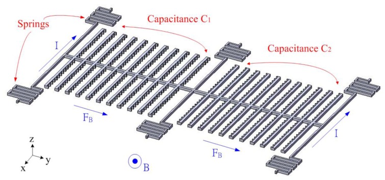
Figure 1 illustrates the schematic structure of the magnetic sensor. The magnetic sensor contains six springs and two set of interdigitated electrodes. The springs are used to support the interdigitated electrodes. As shown in Figure 1, two set of interdigitated electrodes form a differential capacitance couple, where one is capacitance C1 and the other is capacitance C2. The magnetic sensor is actuated by the Lorentz force, and this force is induced by magnetic field. The Lorentz force is given by [22]:
| (1) |
where FB represents the Lorentz force; I is the current; L is the length of conductor and B is the magnetic field. According to Equation (1), we know that the Lorentz force depends on the current and magnetic field.
Figure 1.
Schematic structure of the magnetic sensor, where I is current; B is magnet; FB is Lorentz force.
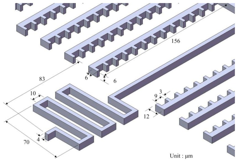
As shown in Figure 1, when supplying a current to the springs in the −x direction and applying a magnetic field in the z direction, the Lorentz force is induced in the y direction. The Lorentz force drives the two set of interdigitated electrodes causing a displacement, and making the capacitances C1 and C2 change. The capacitances C1 and C2 are designed as a pair of differential capacitances. The capacitance C1 undergoes a capacitance increase of ΔC as the capacitance C2 undergoes a capacitance reduction of ΔC. The advantages of a differential capacitance include an enhanced common-mode rejection ratio (CMRR) and reduced harmonic noise. A sensing circuit is utilized to convert the capacitance variation into the output voltage. Figure 2 shows the dimensions of the springs and interdigitated electrodes. The number of interdigitated electrodes is 22, and the number of fingers in each electrode is 13. The gap between the fingers of electrodes is 3 μm.
Figure 2.
Dimensions of the magnetic sensor.
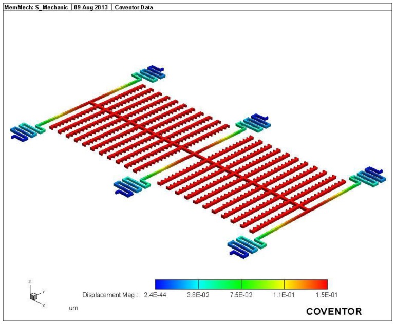
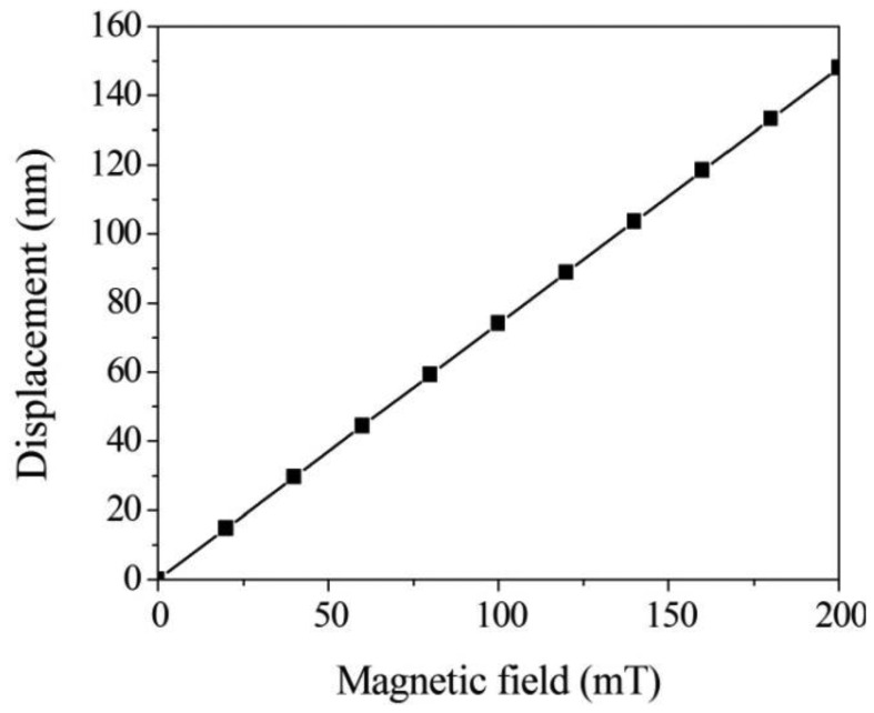
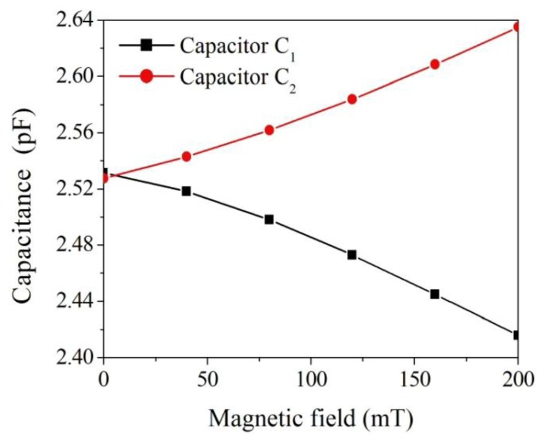
The FEM software CoventorWare was employed to simulate the displacement and capacitance of interdigitated electrodes in the magnetic sensor. As shown in Figure 1, the model of the magnetic sensor is established. The Manhattan bricks mesh type was used to mesh the sensor model. The parabolic hex element type was adopted, and the amount of elements was 5,540. Materials of the magnetic sensor consist of aluminum, tungsten, polysilicon and silicon dioxide. The Young's moduli of the materials are as follows: aluminum, 77 GPa; tungsten, 400 GPa; polysilicon, 160 GPa; silicon dioxide, 70 GPa. The Poisson's ratios of the materials are as follows: aluminum, 0.3; polysilicon, 0.22; tungsten, 0.28; silicon dioxide, 0.17. Figure 3 shows the displacement distribution of the magnetic sensor. In this simulation, a current of 40 mA and a magnetic field of 200 mT are applied to the magnetic sensor. The results show that the interdigitated electrodes have a maximum displacement of 150 nm. Furthermore, the displacement of interdigitated electrodes is evaluated for different magnetic fields. Figure 4 presents the relation between the displacement of interdigitated electrodes and the magnetic field at 40 mA current. The results show that the displacement of interdigitated electrodes is 75 nm at 100 mT. The capacitances C1 and C2 depend on the displacement of the interdigitated electrodes. CoventorWare also can simulate the variation of the capacitances C1 and C2 in the magnetic sensor under different magnetic fields. Figure 5 shows the simulated results of capacitance variation for the capacitances C1 and C2. In this investigation, a current of 40 mA is used. The results show that the capacitance C1 increases from 2.53 to 2.63 pF in the magnetic field range of 0–200 mT, and the capacitance C2 decreases from 2.53 to 2.42 pF in the magnetic field range of 0–200 mT.
Figure 3.
Displacement distribution of the magnetic sensor (unit: μm).
Figure 4.
Displacement of interdigitated electrodes in the magnetic sensor.
Figure 5.
Simulation of capacitance variation in the magnetic sensor.
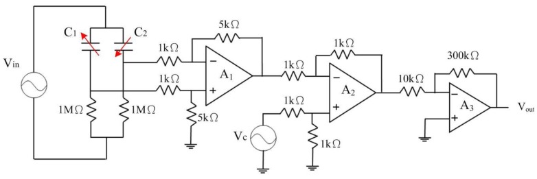
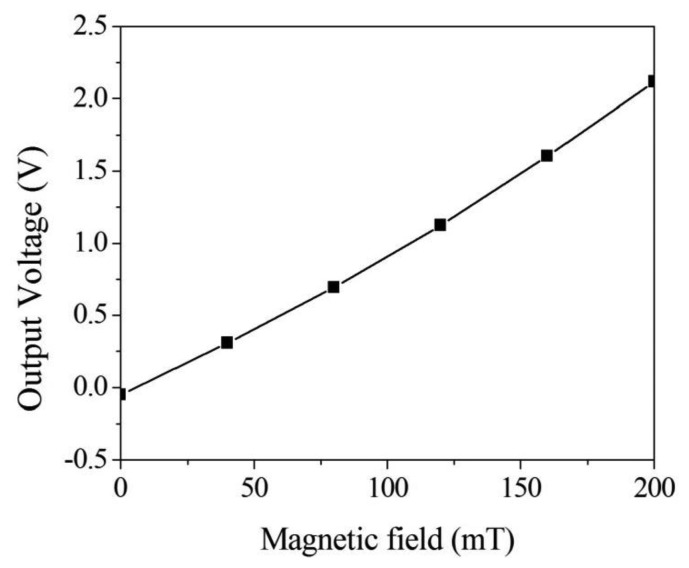
Figure 6 illustrates the sensing circuit for the magnetic sensor, where A1 represents the differential amplifier, A2 is the differential amplifier, A3 is the inverting amplifier, C1 and C2 are the capacitances in the magnetic sensor [23]. The differential amplifier A1 is utilized to reduce common-mode signals and parasitic capacitances. The differential amplifier A2 is used to offset the signal resulting from the residual stress and thermal expansion of the interdigitated electrodes. The inverting amplifier, A3, is employed to amplify the output voltage of the differential amplifier, A2. When the magnetic sensor senses a magnetic field, the capacitances of the magnetic sensor generate a change. The capacitance variation of the magnetic sensor is converted by the sensing circuit into the output voltage. The professional circuitry software HSPICE was used to evaluate the output voltage of the sensing circuit. Figure 7 shows the simulated results of the output voltage for the sensing circuit. In this evaluation, the values in Figure 6 are introduced to the capacitances C1 and C2. The results show that the magnetic sensor with the sensing circuit has an output voltage of 2.1 V at a magnetic field of 200 mT.
Figure 6.
Sensing circuit for the magnetic sensor.
Figure 7.
Simulation of output voltage for the sensing circuit.
3. Fabrication of the Magnetic Sensor
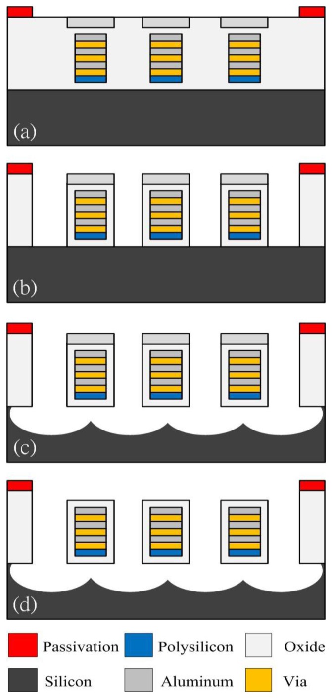
The magnetic sensor was fabricated using the commercial 0.35 μm CMOS process of the Taiwan Semiconductor Manufacturing Company (TSMC, Taipei, Taiwan). Figure 8 illustrates the fabrication flow of the magnetic sensor.
Figure 8.
Fabrication flow of the magnetic sensor, (a) after the CMOS process; (b) removing the oxide layer; (c) etching the silicon substrate; (d) removing the aluminum hard mask.
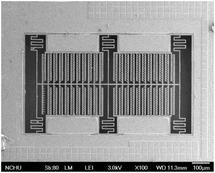
Figure 8a presents the cross-section of the magnetic sensor after completion of the CMOS process. The magnetic sensor needed a post-process [24–26] to release the suspended structure. Figure 8b shows that the sacrificial oxide layer is removed. An anisotropic dry etching of reaction ion etching (RIE) with CHF3 (32 sccm), O2 (8 sccm), pressure (400 mT) and power (100 W) was used to etch the sacrificial oxide layer [27], and to expose the silicon substrate. Figure 8c displays that the silicon substrate is etched. An isotopic dry etching of RIE with SF6 (26 sccm), O2 (5 sccm), pressure (100 mT) and power (150 W) was employed to remove the silicon substrate [28,29], and to release the suspended structure. The top layer of the suspended structures was aluminum as a hard mask for protecting the main structure during the anisotropic etching of RIE with CHF3/O2. The aluminum hard mask must be removed since it increases the residual stress in the structure of the magnetic sensor. Figure 8d shows that the top layer of the suspended structure is removed. An etchant of H3PO4/HNO3/CH3COOH/H2O (16:1:1:2) at 60 °C was utilized to etch the aluminum hard mask, and to obtain the magnetic structure. As shown in Figure 8d, the magnetic sensor is composed of aluminum, via and oxide layers, in which material of via layer is tungsten. The thickness of each material layer is about 1 μm. Figure 9 depicts a scanning electron microscope (SEM) image of the magnetic sensor after the post-process.
Figure 9.
SEM image of the magnetic sensor.
4. Results and Discussion
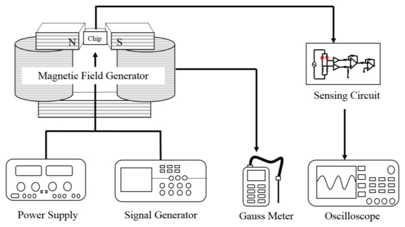
Figure 10 illustrates the experimental set-up of the magnetic sensor. A magnetic field generator, a power supply, a function generator, a gauss meter, and an oscilloscope were used to measure the performance of the magnetic sensor. The power supply was utilized to provide a current to the magnetic field generator. In addition, the power supply was also used to provide a bias voltage to the sensing circuit and a current to the magnetic sensor. The magnetic field generator was employed to produce a magnetic field for testing the magnetic sensor. The gauss meter was adopted to calibrate the magnetic field produced by the magnetic field generator. The oscilloscope was used to record the output voltage of the sensing circuit.
Figure 10.
Measurement set-up of the magnetic sensor.
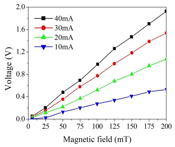
The magnetic sensor produced a capacitance variation when it sensed a magnetic field. The sensing circuit was employed to convert the capacitance variation of the sensor into the output voltage. As shown in Figure 10, the magnetic sensor chip was set in the magnetic field generator. The function generator supplied a signal to the sensing circuit, and the power supply supplied a current to the sensor chip. At the same time, the power supply provided a current to the magnetic field generator that produced a magnetic field applying to the magnetic sensor chip. The output voltage of the magnetic sensor with the sensing circuit was detected by the oscilloscope. Figure 11 shows the measured results of the output voltage for the magnetic sensor under different supplied currents.
Figure 11.
Output voltage of the magnetic sensor.
In this measurement, different currents of 10, 20, 30 and 40 mA, respectively, were supplied to the magnetic sensor, and the magnetic field was changed from 5 to 200 mT. The minimum magnetic field detected by the magnetic sensor was 5 mT. The electronic offset voltage of the magnetic sensor for all currents (10, 20, 30 and 40 mA) was 1.5 V. The magnetic sensor burned out if the current was over 50 mA. The results showed that the output voltage of the sensor varied from 0 to 0.45 V at the current of 10 mA when the magnetic field increased from 5 to 200 mT. The output voltage of the sensor changed from 0.01 to 1.03 V at the current of 20 mA in the magnetic field range of 5–200 mT, and its output voltage varied from 0.03 to 1.51 V at 30 mA current in the magnetic field range of 5–200 mT. As shown in Figure 10, the output voltage of the sensor at 40 mA current exceeded that at 20 mA and 30 mA currents, and the output voltage of the sensor increased as the supplied current increased, resulting from the Lorentz force became large as the supplied current enlarged. When the magnetic field changed from 5 to 200 mT, the output voltage of the magnetic sensor at the current of 40 mA increased from 0.05 to 1.94 V. Therefore, the sensitivity of the magnetic sensor was 9.6 V/T. The power consumption of the magnetic sensor was 3.6 mW at the current of 40 mA. As shown in Figure 7, the simulation results showed the output voltage of the magnetic sensor changed from 0.1 to 2.1 V when the magnetic field increased from 5 to 200 mT, so the simulated sensitivity of the sensor was 10.3 V/T. A comparison of the measured and simulated sensitivities for the sensor, the error percentage was 7%, resulting from the fabrication and testing variations.
Beroulle et al. [30] proposed a piezoresistive magnetic microsensor fabricated using the CMOS process and a bulk wet etching post-process. The magnetic sensor was actuated by the Lorentz force, and the sensitivity of the sensor was 210 mV/T. Herrera-May et al. [31] used MEMS technology to manufacture a resonant magnetic microsensor. The magnetic sensor had a resonant frequency of 22.99 kHz and a sensitivity of 1.94 V/T. Ren et al. [32] developed a torsional resonant magnetometer based on MEMS technology. The magnetometer was a capacitive type, and its sensitivity was 400 mV/μT. Domínguez-Nicolás et al. [33] presented a resonant magnetic microsensor made using MEMS technology, and the sensor had a sensitivity of 4 V/T. In comparison to Beroulle et al. [30], Herrera-May et al. [31] and Domínguez-Nicolás et al. [33], the sensitivity of this work exceeds that of Beroulle et al. [30] and Herrera-May et al. [31]. The power consumption of the magnetic sensor proposed by Choi et al. [7] was 140 μW, and the magnetic sensor presented by Li et al. [8] had a power consumption of 0.58 mW. Comparing to Choi et al. [7] and Li et al. [8], the power consumption of this work is higher than that of both Choi et al. [7] and Li et al. [8].
The main advantage of the proposed magnetic sensor is its integration with the sensing circuit that can reduce the parasitic capacitance and the sensor chip area. The post-process of the magnetic sensor is compatible with the commercial CMOS process, so the sensor has potential for mass-production. The main weakness of the magnetic sensor is its high power consumption.
5. Conclusions
A magnetic sensor has been manufactured using the 0.35 μm CMOS process and appropriate post-processes. The magnetic sensor contained springs and interdigitated electrodes. The FEM software CoventorWare was employed to simulate the displacement and capacitance of the magnetic sensor. The post-process included an anisotropic dry etching of RIE with CHF3/O2 to remove the sacrificial oxide layer, followed by an isotropic dry etching of RIE SF6/O2 to etch the silicon substrate for releasing the suspended structure. Then, an aluminum etchant was used to remove the hard-mask aluminum layer in order to reduce the residual stress of the suspended structure. The post-process was compatible with the commercial CMOS process. The suspended structure in the magnetic sensor, actuated by the Lorentz force, produced a displacement, resulting in a capacitance change of the sensor. The sensing circuit converted the capacitance variation of the sensor into the output voltage. The Lorentz force became large as the current increased, and the output voltage of the senor increased as the current increased. The experimental results showed that the output voltage of the magnetic sensor increased from 0.05 to 1.94 V at the supplied current of 40 mA in a magnetic field range of 5–200 mT. The magnetic sensor had a sensitivity of 9.6 V/T. In the future, we will continue to improve the sensitivity and power consumption of the magnetic sensor and study the sensor's non-linear response, Joule effect, and electronic noise.
Acknowledgments
The authors would like to thank National Center for High-performance Computing (NCHC) for chip simulation; National Chip Implementation Center (CIC) for chip fabrication and the National Science Council of the Republic of China for financially supporting this research under Contract No NSC 101-2221-E-005-006-MY3.
Conflicts of Interest
The authors declare no conflict of interest.
References
- 1.Gardner J.W., Varadan V.K., Awadelkarim O.O. Microsensors MEMS and Smart Devices. John Wiley & Son Ltd.; Chichester, UK: 2001. [Google Scholar]
- 2.Yin X., Jiao Q., Yuan L., Liou S.H. MEMS torsion oscillator magnetic field sensor. IEEE Trans. Magn. 2013;49:3890–3892. [Google Scholar]
- 3.Du G., Chen X., Lin Q., Li H., Guo H. MEMS magnetic field sensor based on silicon bridge structure. J. Semicond. 2010;31 doi: 10.1088/1674-4926/31/10/104011. [DOI] [Google Scholar]
- 4.Lei J., Lei C., Zhou Y. Micro fluxgate sensor using solenoid coils fabricated by MEMS technology. Meas. Sci. Rev. 2012;12:286–289. [Google Scholar]
- 5.Brugger S., Paul O. Field-concentrator-based resonant magnetic sensor with integrated planar coils. J. Microelectromech. Syst. 2009;18:1432–1443. [Google Scholar]
- 6.Marauska S., Jahns R., Kirchhof C., Claus M., Quandt E., Knöchel R., Wagner B. Highly sensitive wafer-level packaged MEMS magnetic field sensor based on magnetoelectric composites. Sens. Actuators A. 2013;189:321–327. [Google Scholar]
- 7.Choi S., Yoon Y.K., Kim S.H., Allen M.G. Nonlinear sensitivity enhancement of resonant microsensors and its application to low power magnetic sensing. J. Micromech. Microeng. 2011;21 doi: 10.1088/0960-1317/21/4/045004. [DOI] [Google Scholar]
- 8.Li M., Rouf V.T., Thompson M.J., Horsley D.A. Three-axis Lorentz-force magnetic sensor for electronic compass applications. J. Microelectromech. Syst. 2012;21:1002–1010. [Google Scholar]
- 9.Langfelder G., Buffa C., Frangi A., Tocchio A., Lasalandra E., Longoni A. Z-axis magnetometers for MEMS inertial measurement units an industrial process. IEEE Trans. Ind. Electron. 2013;60:3983–3990. [Google Scholar]
- 10.Dominguez-Nicolas S.M., Juarez-Aguirre R., Herrera-May A.L., Garcia-Ramirez P.J., Figueras E., Gutierrez E., Tapia J.A., Trejo A., Manjarrez E. Respiratory magnetogram detected with a MEMS device. Int. J. Med. Sci. 2013;10:1445–1450. doi: 10.7150/ijms.4732. [DOI] [PMC free article] [PubMed] [Google Scholar]
- 11.Thompson M.J., Horsley D.A. Parametrically amplified z-axis Lorentz force magnetometer. J. Microelectromech. Syst. 2011;20:702–710. [Google Scholar]
- 12.Tapia J.A., Herrera-May A.L., Garcia-Ramirez P.J., Martinez-Castillo J., Figueras E., Flores A., Manjarrez E. Sensing magnetic flux density of artificial neurons with a MEMS device. Biomed. Microdev. 2011;13:303–313. doi: 10.1007/s10544-010-9494-2. [DOI] [PubMed] [Google Scholar]
- 13.Wu G., Xu D., Xiong B., Feng D., Wang Y. Resonant magnetic field sensor with capacitive driving and electromagnetic induction sensing. IEEE Electron Dev. Lett. 2013;34:459–461. [Google Scholar]
- 14.Dai C.L., Chen Y.L. Modeling and manufacturing of micromechanical RF switch with inductors. Sensors. 2007;7:2660–2670. doi: 10.3390/s7112670. [DOI] [PMC free article] [PubMed] [Google Scholar]
- 15.Kao P.H., Dai C.L., Hsu C.C., Lee C.Y. Fabrication and characterization of a tunable in-plane resonator with low driving voltage. Sensors. 2009;9:2062–2075. doi: 10.3390/s90302062. [DOI] [PMC free article] [PubMed] [Google Scholar]
- 16.Dai C.L., Kou C.H., Chiang M.C. Microelectromechanical resonator manufactured using CMOS-MEMS technique. Microelectron. J. 2007;38:672–677. [Google Scholar]
- 17.Kao P.H., Shin P.J., Dai C.L., Liu M.C. Fabrication and characterization of CMOS-MEMS thermoelectric micro generators. Sensors. 2010;10:1315–1325. doi: 10.3390/s100201315. [DOI] [PMC free article] [PubMed] [Google Scholar]
- 18.Dai C.L., Tai Y.W., Kao P.H. Modeling and fabrication of micro FET pressure sensor with circuits. Sensors. 2007;7:3386–3398. doi: 10.3390/s7123386. [DOI] [PMC free article] [PubMed] [Google Scholar]
- 19.Yang M.Z., Dai C.L., Lu D.H. Polypyrrole porous micro humidity sensor integrated with a ring oscillator circuit on chip. Sensors. 2010;10:10095–10104. doi: 10.3390/s101110095. [DOI] [PMC free article] [PubMed] [Google Scholar]
- 20.Dai C.L., Lu P.W., Chang C., Liu C.Y. Capacitive micro pressure sensor integrated with a ring oscillator circuit on chip. Sensors. 2009;9:10158–10170. doi: 10.3390/s91210158. [DOI] [PMC free article] [PubMed] [Google Scholar]
- 21.Dai C.L., Chen J.H. Low voltage actuated RF micromechanical switches fabricated using COMS-MEMS technique. Microsyst. Technol. 2006;12:1143–1151. [Google Scholar]
- 22.Bahreyni B., Shafai C.A. A resonant micromachined magnetic field sensor. Sensors. 2007;7:1326–1334. [Google Scholar]
- 23.Sedra A.S., Smith K.C. Microelectronic Circuits. Oxford University Press; New York, NY, USA: 1998. [Google Scholar]
- 24.Dai C.L., Hsu H.M., Tai M.C., Hsieh M.M., Chanh M.W. Modeling and fabrication of a microelectromechanical microwave switch. Microelectron. J. 2007;38:519–524. [Google Scholar]
- 25.Dai C.L., Peng H.J., Liu M.C., Wu C.C., Hsu H.M., Yang L.J. A micromachined microwave switch fabricated by the complementary metal oxide semiconductor post-process of etching silicon dioxide. Jpn. J. Appl. Phys. 2005;44:6804–6809. [Google Scholar]
- 26.Dai C.L. A maskless wet etching silicon dioxide post-CMOS process and its application. Microelectron. Eng. 2006;83:2543–2550. [Google Scholar]
- 27.Cheng Y.C., Dai C.L., Lee C.L., Chen P.H., Chang P.Z. A circular micromirror array fabricated by a maskless post-CMOS process. Microsyst. Technol. 2005;11:444–451. [Google Scholar]
- 28.Dai C.L., Xiao F.Y., Juang Y.Z., Chiu C.F. An approach to fabricating microstructures that incorporate circuits using a post-CMOS process. J. Micromech. Microeng. 2005;15:98–103. [Google Scholar]
- 29.Dai C.L., Chen H.L., Chang P.Z. Fabrication of a micromachanied optical modulator using the CMOS process. J. Micromech. Microeng. 2001;11:612–615. [Google Scholar]
- 30.Beroulle V., Bertrand Y., Latorre L., Nouet P. Monolithic piezoresistive CMOS magnetic field sensors. Sens. Actuators A. 2003;103:23–32. [Google Scholar]
- 31.Herrera-May A.L., García-Ramírez P.J., Aguilera-Cortés L.A., Figueras E., Martinez-Castillo J., Manjarrez E., Sauceda A., García-González L., Juárez-Aguirre R. Mechanical design and characterization of a resonant magnetic field microsensor with linear response and high resolution. Sens. Actuators A. 2011;165:399–409. [Google Scholar]
- 32.Ren D., Wu L., Yan M., Cui M., You Z., Hu M. Design and analysis of a MEMS based resonant magnetometer. Sensors. 2009;9:6951–6966. doi: 10.3390/s90906951. [DOI] [PMC free article] [PubMed] [Google Scholar]
- 33.Domínguez-Nicolás S.M., Juárez-Aguirre R., García-Ramírez P.J., Herrera-May A.L. Signal conditioning system with a 4–20 mA output for a resonant magnetic field sensor based on MEMS technology. IEEE Sens. J. 2012;12:935–942. [Google Scholar]


