Abstract
3D structures were written and developed in a crosslinked polymer initially formed by a Diels–Alder reaction. Unlike conventional liquid resists, small features cannot sediment, as the reversible crosslinks function as a support, and the modulus of the material is in the MPa range at room temperature. The support structure, however, can be easily removed by heating the material which depolymerizes the polymer into a mixture of low-viscosity monomers. Complex shapes were written into the polymer network using two-photon techniques to spatially control the photoinitiation and subsequent thiol–ene reaction to selectively convert the Diels–Alder adducts into irreversible crosslinks.
Keywords: Diels–Alder, microfabrication, polymerization, thiol-ene, two-photon
Introduction
Top down fabrication techniques such as deep UV and electron beam lithography allow the fabrication of complex two-dimensional (2D) patterns on nanometer size scales, and enable the creation of powerful and ubiquitous personal electronic devices, as well other technologies.[1, 2] However, the fabrication of three dimensional (3D) structures with overhanging and free standing elements still presents significant difficulties. Freeform fabrication techniques, such as laser sintering,[3] 3D printing,[4] fused deposition modeling,[5] block stacking,[6] and capillary origami,[7] are limited in resolution and the range of shapes obtainable.[8] Importantly, such complex structures are often key to emerging technologies such as photonic devices[9, 10] and tissue engineering scaffolds.[11]
Conventional photolithography begins with the preparation of a photoactive thin film on a substrate (photoresist). A pattern is then transferred to the photoresist using masked or focused laser selectively that removes the exposed material in a positive photoresist or the unexposed material in a negative photoresist. 3D structures can be fabricated by using an inert filler material to backfill the space previously occupied by the photoresist, and planarize the sample. A subsequent layer is then written, and the process is iterated. After fabrication of the desired number of layers, the filler is removed, typically by dissolution. While this approach leverages well developed conventional techniques for pattern transfer and development, controlling the alignment and adhesion of multiple layers and the removal of the filler material presents significant technical challenges.[9, 12] Alternatively, optical direct write lithographic techniques (ODWL), utilize a stage suspended in a vat of liquid photoresist.[13, 14] The first layer is written by rastering a laser across the surface of the stage to sollidify the liquid resist. The stage is then lowered and a subsequent layer is written on top. While this approach reduces the total number of steps it still presents significant challenges. First, the 3D construction of non-contiguous objects in a liquid negative tone photoresist is often problematic as each underlying layer must support the next layer, or overhanging features will sediment from the densification associated with the polymerization. Sedimentation is reduced by utilizing higher viscosity photoresists; however, this approach complicates the later removal of the unreacted resist while preserving fragile features. Alternatively, workers have sought to develop routines that write important structural features first, and only partially cure each layer. A complete flood cure after the sample is removed from the vat is required to reach final material properties, which may result in sagging features, shrinkage, or distortion.[15]
We overcome the tradeoff between resist viscosity and ease of removal in ODWL by using a reversibly crosslinked polymer as a photoresist. In the polymerized state the material is an elastic or even glassy solid that acts as a scaffold, supporting structures during the image transfer process. Upon external stimulation the material can depolymerize to a sol composed of low viscosity monomer.
Experimental Section
Unless noted all materials were used as received. Compound (5) was prepared as described in [16], and (8) was adapted from procedures described in.[17]
Photoresist Synthesis
A stoichiometric mixture of furan, maleimide, and thiol groups was prepared using 5, 6, and 7, to which was added 1% weight 8. A slight amount of heat or solvent (dichloromethane) was necessary to melt 6. Samples for dynamic mechanical analysis were prepared using 1-hydroxy-cyclohexyl-phenyl-ketone (Irgacure 184, Ciba) so that the films were less optically dense. Irradiated samples were cured for 1000 s at light intensity of 10 mW/cm2 using a irradiated by an EXFO Acticure high pressure mercury vapor short arc lamp equipped with a 365 nm bandpass filter.
Fourier Transform Infrared (FTIR) Spectroscopy
Samples for IR spectroscopy were produced by casting a thin film of the reactants in dichloromethane onto a NaCl crystal and evaporating the solvent under vacuum. Equilibrium was reached at approximately 4 hours. The samples were irradiated by an EXFO Acticure mercury vapor arc lamp equipped with a 365 nm bandgap filter.
2-Photon lithography
3D patterning was obtained via two-photon techniques, where the gel was selectively exposed to pulsed laser light from a Chameleon II Ultra laser (l = 740 nm, pulse frequency 80 MHz, pulse duration = 140 fs, power = 670 mW/mm2, scan speed = 1.27 msec/mm2) at 1 mm z-plane increments on a 710 LSM NLO confocal microscope stage (Carl Zeiss) equipped with a 20× Plan-Apochromat objective (NA = 1.0, Carl Zeiss).
Results and Discussion
While reversibly crosslinked polymers may be formed by several reactions,[18] few are as robust or possess the unique behavior of the Diels–Alder reaction between furan (1) and maleimide (2) (Figure 1 and Figure 2). Upon heating, the Diels–Alder adduct (3) readily undergoes a retro-Diels–Alder reaction to recover (1) and (2). This behavior can be reversed many times,[19] and only ceases when side-reactions render the Diels–Alder adduct irreversible.[20] Fortuitously, such reactions can be easily triggered, as the oxy-norbornene adduct (3) was found to exhibit excellent reactivity via the thiol–ene reactions. The strained nature of the olefinic bond in the oxy-norbornene makes it a preferable ene for the radical-mediated thiol–ene addition, while the electrically activated maleimide is less reactive towards the thiol–ene reaction and has a greater tendency to homopolymerize.[21]
Figure 1.
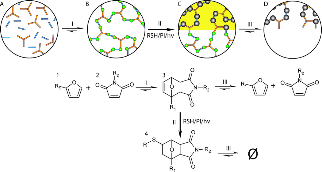
First, multi-functional furan (1) and maleimide (2) monomers (bubble A) form a crosslinked polymer (bubble B) by the Diels–Alder reaction (reaction I). In the irradiated areas (bubble C) the resulting oxy-norbornene groups (3) are then selectively converted to irreversible crosslinks (4) by radical reactions with thiol molecules freely suspended in the polymer network (reaction II). The pattern is then developed by selectively removing the remaining material in the non-irradiated areas by shifting chemical equilibrium such that the retro-Diels–Alder reaction (reaction III) occurs and the material depolymerizes (bubble D).
Figure 2.
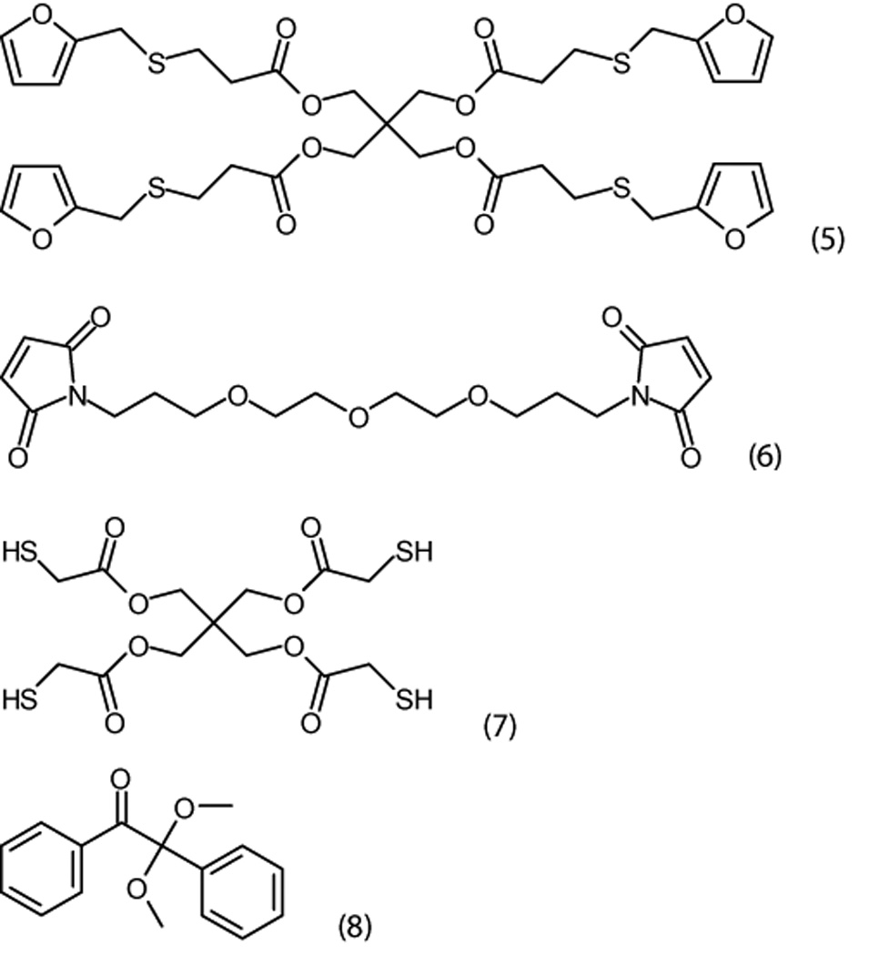
Specific chemical structures: tetrakis furfurylthiopropionate (5); 1,13-bismaleimido 4,7,10-trioxatridecane (6); pentaerythritol tetrakis 3-mercaptopropionate (7); and 2,2-dimethoxy-1,2-diphenylethanone (8).
While the addition of the thiol-functionalized species enables photofixation, it is worth noting that the thiol can potentially undergo the base-catalyzed Michael addition reaction with the maleimide. This reaction is often employed in protein functionalization owing to its ease and high yield.[22] However, in the absence of a nucleophile or base, the thiolate anion is never formed, which effectively prevents the Michael addition from occurring. The addition of a small amount of acid is sufficient to prevent the unwanted thiol–maleimide reaction. In the present case, the thiol utilized in these studies (6) contains sufficient trace levels of acid impurities, to retard the thiol-maleimide reaction. In Figure 3a infrared spectroscopy reveals that when a stoichiometric mixture of (5), (6), (7), and 1% wt. (8) is equilibrated at 80 °C for 4 hours, 86% furan and 88% maleimide are consumed via the Diels–Alder reaction, while less than 1% of the thiol is reacted. Consequently, bulk samples are readily prepared by mixing the components, spin coating a substrate, and then baking the sample. After irradiation with 365 nm light at an intensity of 10 mW/cm2 for 10 minutes infrared spectroscopy further reveals that the complete consumption of the free maleimide and oxy-norbornene groups, accompanied by 70% conversion of the thiol (Figure 3a). This result indicates that the thiol–ene reaction dominates over homo- and co-polymerization of the oxy-norbornene and maleimide. Further, the complete reaction of the maleimide and oxy-norbornene guarantees that no reversible bonds remain after irradiation. Notably, as the chemical details of the thiol-bearing species are of minor importance,[23] and this click chemistry approach could be also be used to incorporate additional chemical functionality within the polymer network with spatial control of its addition.
Figure 3.
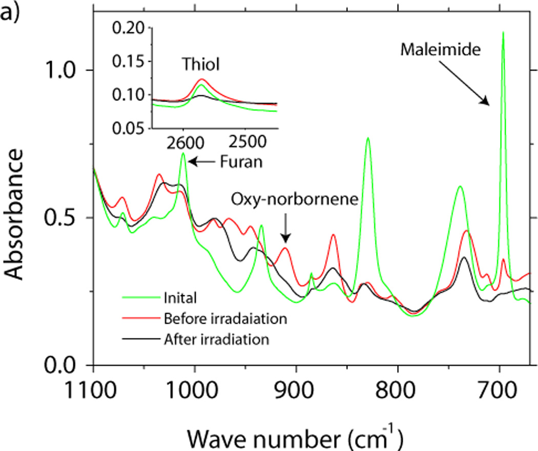
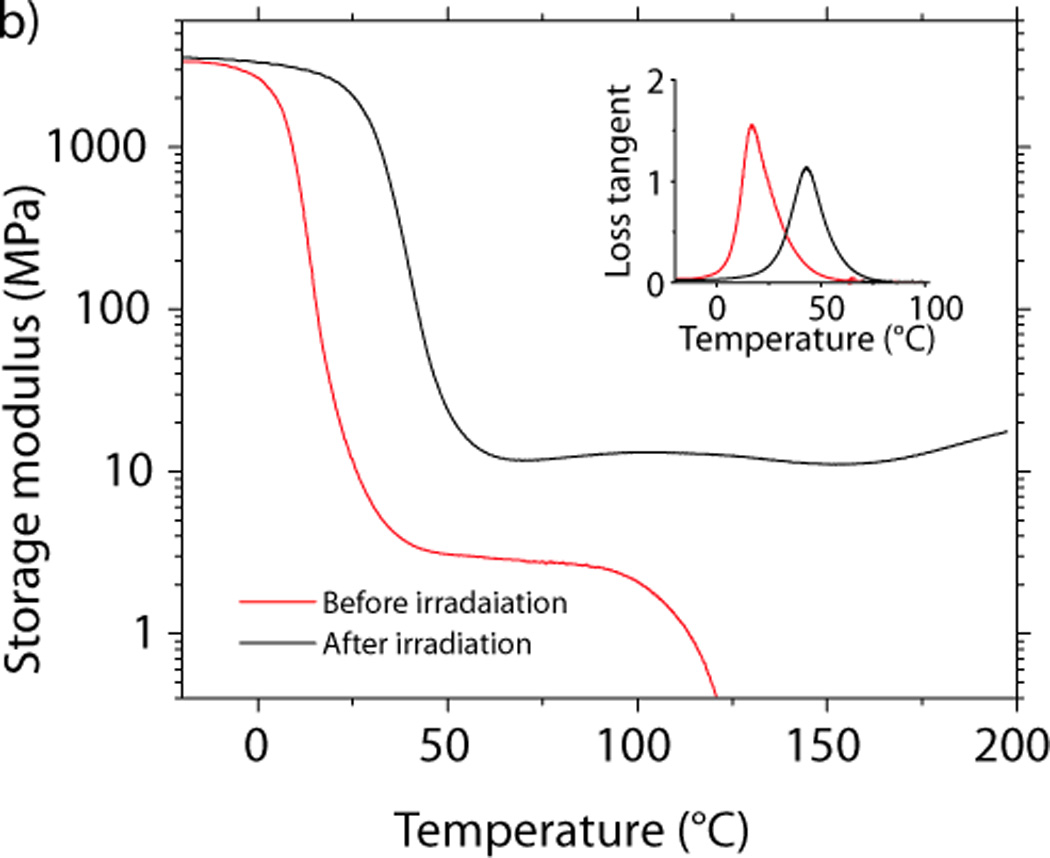
a) The FTIR spectrum of a stoichiometric mixture of (5), (6), (7), and (8) before thermal curing, after the thermal curing, and after irradiation. b) Dynamic mechanical analysis of the material before and after irradiation.
The ratio of the storage modulus at 75 °C, before and after irradiation shows that the crosslinking density increases more than fourfold during photofixation due to the multifunctional nature of the thiol (Figure 3b). The photofixation reaction is also accompanied by a modest increase in the glass transition temperature, which rises from 16 °C to 43 °C. Furthermore, after photofixation, the breadth of the glass transition temperature does not increase, supporting the hypothesis that the primary mode of polymerization is via the step-growth thiol–ene reaction, whereas chain growth mechanisms tend to produce a more heterogeneous network structure and therefore would be expected to broaden the glass transition.[24]
Direct writing of 3D patterns into the bulk material presents two additional challenges. First, light must be transmitted deep into the material to initiate radical generation. Second, out-of-focus light must be minimized to prevent unconfined reactions away from the focal plane. While researchers have demonstrated a number of techniques to reduce out of focus reactions,[13, 25] both problems are diminished by utilizing two-photon optical direct write lithography. Two-photon absorptions typically occur at longer wavelengths, where single-photon absorption, with its associated photochemical reactions, is reduced. This enables deeper penetration of light into the sample. Additionally, out-of-focus reactions are minimized as two-photon absorption is proportional to the square of the light intensity, rather than directly proportional, better confining two-photon initiation to the focal plane.
Irradiation of the material with a 740 nm femtosecond pulsed laser produced a refractive index change within the sample, allowing immediate visualization of written shapes prior to any heating and image development. After heating the sample to 105 °C in furfuryl alcohol, the unexposed material depolymerized and the 3D structures were carefully recovered from the developing liquid. Complex structures that are difficult to produce by other techniques, such as freely rotating interlocked rings or log pile-type structures, are easily fabricated using this 3D patterning approach (Figure 4). While the structures demonstrated herein are 10s of µm in size, the primary benefit of this process is not improved resolution though many current techniques inspired by stimulated excitation depletion spectroscopy and used in ODWL[33–35] could be utilized to improve it. The inherent advantage of the photofixation process demonstrated here is that it uniquely addresses the separate problems of sagging features and shrinkage to enable fabrication of complex 3D devices. This problem is an important one that has not been solved by improvements in resolution, scanning routines, or by accounting for shrinkage in structure design.[26]
Figure 4.
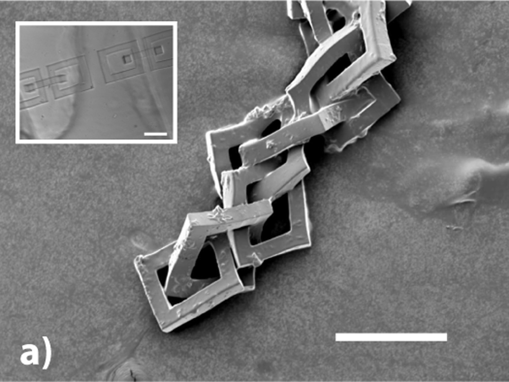
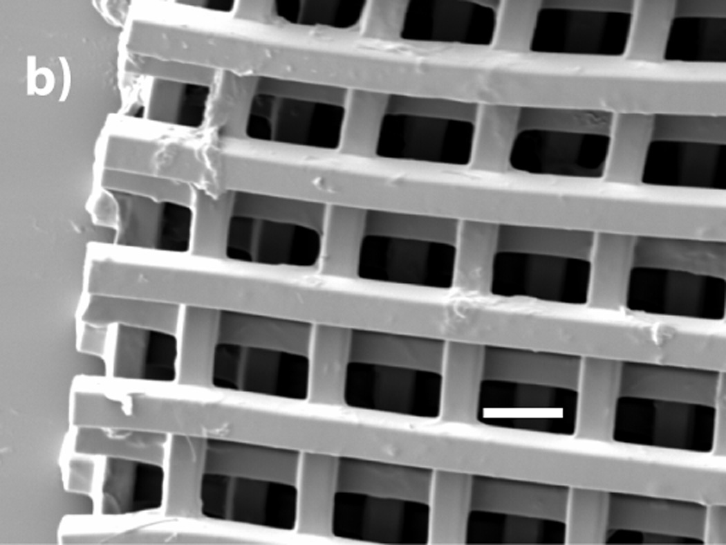
a) SEM micrograph of 8 freely rotating rings written using two-photon techniques (200 µm scale bar). The inset optical micrograph shows two sets of interlocking rings before the retro-Diels–Alder reaction is used to remov the surrounding material (200 µm scale bar). (b) SEM micrograph of a five layer log pile type structure (40 µm scale bar).
Conclusion
The use of a reversibly crosslinked polymer network as a photoresist has a number of potential advantages. It is expected that diffusion of the active species in such systems will be significantly retarded by the polymer network, enhancing the feature resolution. Furthermore, thin films can be prepared without the use of volatile organic solvents, because the starting materials are low viscosity monomers, rather than linear polymers that are employed in conventional photoresists (i.e., SU-8 popularized by soft-lithography[1]). Moreover, it is also possible that the use of solvents could be eliminated in the image development step as well. Photofixation also provides a method to eliminate thermoreversible behavior within reversible adhesives, self-healing materials,[27] non-linear optics,[28] polymer encapsulants[29], and may even be applicable to locking in dynamic combinatorial libraries.[30] Finally, the utilization of photofixation lithography in conjunction with thiol-functionalized materials, such as cysteine-terminated peptides, thiol functionalized nanoparticles, and thiol-functionalized sensing moieties, would enable the simultaneous fabrication of complex 3D structures with uniquely defined chemical functionalization for an array of applications.
Acknowledgements
This work was supported by funding from U.S. Departments of Education’s Graduate Assistantship in Areas of National Need (BJA and CAD), the National Science Foundation Grant CBET 0933828 (CJK), and Sandia National Laboratories.
Contributor Information
Brian J. Adzima, Department of Chemical and Biological Engineering, University of Colorado, Boulder CO 80309-0424, USA
Christopher J. Kloxin, University of Delaware, Department of Materials Science and Engineering & Department of Chemical Engineering, Newark DE 19716 USA
Cole A. DeForest, Department of Chemical and Biological Engineering, University of Colorado, Boulder CO 80309-0424, USA
Kristi S. Anseth, Howard Hughes Medical Institute, University of Colorado, Boulder CO 80309-0424, USA
Christopher N. Bowman, Email: christopher.bowman@colorado.edu, Department of Chemical and Biological Engineering, University of Colorado, Boulder CO 80309-0424, USA.
References
- 1.Duffy DC, McDonald JC, Schueller OJA, Whitesides GM. Anal. Chem. 1998;70:4974. doi: 10.1021/ac980656z. [DOI] [PubMed] [Google Scholar]
- 2.Burckel DB, Wendt JR, Ten Eyck GA, Ginn JC, Ellis AR, Brener I, Sinclair MB. Adv. Mater. 2010;22:5053. doi: 10.1002/adma.201002429. [DOI] [PubMed] [Google Scholar]; Khademhosseini A, Langer R. Biomaterials. 2007;28:5087. doi: 10.1016/j.biomaterials.2007.07.021. [DOI] [PubMed] [Google Scholar]; Fodor SPA, Read JL, Pirrung MC, Stryer L, Lu AT, Solas D. Science. 1991;251:767. doi: 10.1126/science.1990438. [DOI] [PubMed] [Google Scholar]
- 3.Bourell DL, Marcus HL, Barlow JW, Beaman JJ. Int. J. Powder Metall. 1992;28:369. [Google Scholar]
- 4.Mironov V, Boland T, Trusk T, Forgacs G, Markwald RR. Trends Biotechnol. 2003;21:157. doi: 10.1016/S0167-7799(03)00033-7. [DOI] [PubMed] [Google Scholar]; Sachs EM, Haggerty JS, Cima MJ, Williams PA. US 5204055. Massachesets Innsitute of Technology. 1989
- 5.Zein I, Hutmacher DW, Tan KC, Teoh SH. Biomaterials. 2002;23:1169. doi: 10.1016/s0142-9612(01)00232-0. [DOI] [PubMed] [Google Scholar]
- 6.Zhang H, Burdet E, Poo AN, Hutmacher DW. IEEE Trans. Autom. Sci. Eng. 2008;5:446. [Google Scholar]
- 7.Py C, Reverdy P, Doppler L, Bico J, Roman B, Baroud CN. Phys. Rev. Lett. 2007;98:4. doi: 10.1103/PhysRevLett.98.156103. [DOI] [PubMed] [Google Scholar]
- 8.Leong KF, Cheah CM, Chua CK. Biomaterials. 2003;24:2363. doi: 10.1016/s0142-9612(03)00030-9. [DOI] [PubMed] [Google Scholar]
- 9.Lin SY, Fleming JG, Hetherington DL, Smith BK, Biswas R, Ho KM, Sigalas MM, Zubrzycki W, Kurtz SR, Bur J. Nature. 1998;394:251. [Google Scholar]; Liu N, Guo H, Fu L, Kaiser S, Schweizer H, Giessen H. Nat. Mater. 2008;7:31. doi: 10.1038/nmat2072. [DOI] [PubMed] [Google Scholar]
- 10.Tetreault N, von Freymann G, Deubel M, Hermatschweiler M, Perez-Willard F, John S, Wegener M, Ozin GA. Adv. Mater. 2006;18:457. [Google Scholar]
- 11.Hutmacher DW, Sittinger M, Risbud MV. Trends Biotechnol. 2004;22:354. doi: 10.1016/j.tibtech.2004.05.005. [DOI] [PubMed] [Google Scholar]; Hollister SJ. Nat. Mater. 2005;4:518. doi: 10.1038/nmat1421. [DOI] [PubMed] [Google Scholar]
- 12.Hutchison JB, Haraldsson KT, Good BT, Sebra RP, Luo N, Anseth KS, Bowman CN. Lab Chip. 2004;4:658. doi: 10.1039/b405985a. [DOI] [PubMed] [Google Scholar]
- 13.Kawata S, Sun HB, Tanaka T, Takada K. Nature. 2001;412:697. doi: 10.1038/35089130. [DOI] [PubMed] [Google Scholar]
- 14.Zhou W, Kuebler SM, Braun KL, Yu T, Cammack JK, Ober CK, Perry JW, Marder SR. Science. 2002;296:1106. doi: 10.1126/science.296.5570.1106. [DOI] [PubMed] [Google Scholar]; Scott TF, Kloxin CJ, Forman DL, McLeod RR, Bowman CN. J. .Mater. Chem. 2011 [Google Scholar]
- 15.Wang WL, Cheah CM, Fuh JYH, Lu L. Mater. Des. 1996;17:205. [Google Scholar]; Yang DY, Park SH, Lim TW, Kong HJ, Yi SW, Yang HK, Lee KS. Appl. Phys. Lett. 2007;90:3. [Google Scholar]
- 16.Sheridan RJ, Adzima BJ, Bowman CN. Aust. J. Chem. 64:1094. [Google Scholar]
- 17.Reddy PY, Kondo S, Toru T, Ueno Y. J. Org. Chem. 1997;62:2652. doi: 10.1021/jo962202c. [DOI] [PubMed] [Google Scholar]
- 18.Engle LP, Wagener KB. J. Macrmol. Sci. R. M C. 1993;C33:239. [Google Scholar]; Kloxin CJ, Scott TF, Adzima BJ, Bowman CN. Macromolecules. 2010;43:2643. doi: 10.1021/ma902596s. [DOI] [PMC free article] [PubMed] [Google Scholar]
- 19.Adzima BJ, Kloxin CJ, Bowman CN. Adv. Mat. 2010;22:2784. doi: 10.1002/adma.200904138. [DOI] [PubMed] [Google Scholar]
- 20.Adzima BJ, Aguirre HA, Kloxin CJ, Scott TF, Bowman CN. Macromolecules. 2008;41:9112. doi: 10.1021/ma801863d. [DOI] [PMC free article] [PubMed] [Google Scholar]
- 21.Hoyle CE, Bowman CN. Angew. Chem. Int. Edit. 2010;49:1540. doi: 10.1002/anie.200903924. [DOI] [PubMed] [Google Scholar]
- 22.Jones MW, Mantovani G, Ryan SM, Wang XX, Brayden DJ, Haddleton DM. Chem. Commun. 2009:5272. doi: 10.1039/b906865a. [DOI] [PubMed] [Google Scholar]
- 23.Hoyle CE, Lowe AB, Bowman CN. Chem. Soc. Rev. 2010;39:1355. doi: 10.1039/b901979k. [DOI] [PubMed] [Google Scholar]
- 24.Bowman CN, Kloxin CJ. AICHE J. 2008;54:2775. [Google Scholar]
- 25.Li LJ, Gattass RR, Gershgoren E, Hwang H, Fourkas JT. Science. 2009;324:910. doi: 10.1126/science.1168996. [DOI] [PubMed] [Google Scholar]; Scott TF, Kowalski BA, Sullivan AC, Bowman CN, McLeod RR. Science. 2009;324:913. doi: 10.1126/science.1167610. [DOI] [PubMed] [Google Scholar]; Andrew TL, Tsai HY, Menon R. Science. 2009;324:917. doi: 10.1126/science.1167704. [DOI] [PubMed] [Google Scholar]
- 26.Lee KS, Yang DY, Park SH, Kim RH. 2006;17:72. [Google Scholar]; Park S-H, Yang D-Y, Lee K-S. 2009;3:1. [Google Scholar]
- 27.Chen XX, Dam MA, Ono K, Mal A, Shen HB, Nutt SR, Sheran K, Wudl F. Science. 2002;295:1698. doi: 10.1126/science.1065879. [DOI] [PubMed] [Google Scholar]
- 28.Shi Z, Hau S, Luo J, Kim TD, Tucker NM, Ka JW, Sun H, Pyajt A, Dalton L, Chen A, Jen AKY. Adv. Func. Mater. 2007;17:2557. [Google Scholar]
- 29.McElhanon JR, Russick EM, Wheeler DR, Loy DA, Aubert JH. J. Appl. Polym. Sci. 2002;85:1496. [Google Scholar]
- 30.Lehn J-M. Chem.–Eur. J. 1999;5:2455. [Google Scholar]


