Abstract
Differential phase contrast technique could be the next breakthrough in the field of CT imaging. While traditional absorption-based X-ray CT imaging is inefficient at differentiating soft tissues, phase-contrast technique offers great advantage as being able to produce higher contrast images utilizing the phase information of objects. Our long term goal is to develop a gantry-based hospital-grade X-ray tube differential phase contrast cone-beam CT (DPC-CBCT) technology which is able to achieve higher contrast noise ratio (CNR) in soft tissue imaging without increasing the dose level. Based on the micro-focus system built last year, a bench-top hospital-grade X-ray tube DPC-CBCT system is designed and constructed. The DPC-CBCT system consists of an X-ray source, i.e. a hospital-grade X-ray tube and a source grating, a high-resolution detector, a rotating phantom holder, a phase grating and an analyzer grating. Three-dimensional (3-D) phase-coefficients are reconstructed, providing us with images enjoying higher CNR than, yet equivalent dose level to, a conventional CBCT scan. Three important aspects of the system are investigated: a) The The system’s performance in term of CNR of the reconstruction image with regard to dose levels, b) the impacts of different phase stepping schemes, i.e. 5 steps to 8 steps, in term of CNR on the reconstruction images, and c) the influence of magnification or position of the phantom on image quality, chiefly CNR. The investigations are accomplished via phantom study.
Keywords: Phase Contrast, Differential phase-contrast, cone beam CT
1. INTRODUCTION
Phase-contrast technique is promising as the next breakthrough in X-ray imaging and CT field. Utilizing the long ignored X-ray phase information, phase contrast technique has the potential of providing higher contrast projection images in a CT scan thus leading to a more realistic reconstruction of the scanned object. Various phase-contrast techniques have been developed for X-ray imaging, including X-ray interferometry[1–3], diffraction enhanced imaging [4–6] and in-line propagation method[7–9]. Differential phase-contrast (DPC) technique is a comparatively new method that greatly looses the coherence requirements for phase-contrast X-ray imaging. Based on a set of gratings, i.e. one phase grating and one analysis grating, the method extracts the phase information from a set of acquired images via the approach of phase stepping. The deployment of a source grating, which divides the incident beam from a big focal spot into several narrow line sources and by doing so increasing the coherence of the source, yields DPC capable of employing a hospital-grade X-ray tube. Detailed principles of the grating-based DPC system have been well documented [10–12]. As DPC method measures the first derivative of phase projection, it falls into the second category as listed above.
As absorption-based X-ray CT is not very efficient in differentiate certain materials, e.g. soft tissue, it is natural to extend the DPC technique to tomography imaging [12]. In our lab, we are working on implementing the differential phase contrast (DPC) technique in a cone beam CT (CBCT) bench top imaging system[13–15]. The resulting system enables us to differential-phase-contrast-based cone-beam CT (DPC-CBCT) scans which are expected to yield reconstruction images of better quality compared with absorption-based CT scans for the same X-ray dose level. The conventional CBCT reconstruction algorithm has also been modified into a DPC-CBCT reconstruction algorithm with a Hilbert filter replacing the ramp filter.
Based on the existing differential phase contrast cone beam CT system using a micro-focus X-ray tube[15], a differential phase contrast cone beam CT system is designed and constructed. Details of the design and construction are reported in this paper. With system constructed, we investigate its performance with a focus on dose efficiency. Two aspects of the system are investigated: a) The image quality of the reconstruction image with regard to dose levels in each step image, and b) the impacts of different phase stepping schemes, i.e. 6 steps to 8 steps, on the reconstruction images. The performance investigations are accomplished via phantom studies.
2. METHOD
2.1 System components and configuration
Based on the existing micro-focus system, a new DPC-CBCT system with a hospital-grade x-ray tube was constructed. There are two major improvements, namely (1) the phase and analyzer gratings have larger effective areas and better quality and (2) the source grating, which enables us to apply a hospital-grade X-ray tube. Details of the system could be found in the table below. (Table 1). Figure 1 illustrates the bench-top DPC-CBCT system, the positioning of its components, including a hospital-grade x-ray tube, a source grating, a high resolution CMOS detector, a set of phase and analyzer gratings, and a phantom stage. The major system parameters are listed in Table 1.
Table 1.
Bench-top DPC-CBCT system parameters
| Focal spot size | 0.3 mm |
| Detector pixel size | 22.5 μm |
| Source-to-phase-grating distance | 118 cm |
| Phase-to-analysis-grating distance | 17.72 cm |
| Object-to-detector distance | 25.4 mm |
| Field of view | 32 mm × 24 mm |
| Cone angle | < 2° |
| Tube peak voltage | 25–49.5 kVp |
| Tube current | 16–200 mA |
| Exposure time per exporsure | 320 ms |
| Projection number | 120 |
| Recon voxel size | (36.8 μm)3 |
| Phase grating period | 8.0 micron |
| Analyzer grating period | 4.6 micron |
| Source grating period | 30 micron |
Fig. 1.
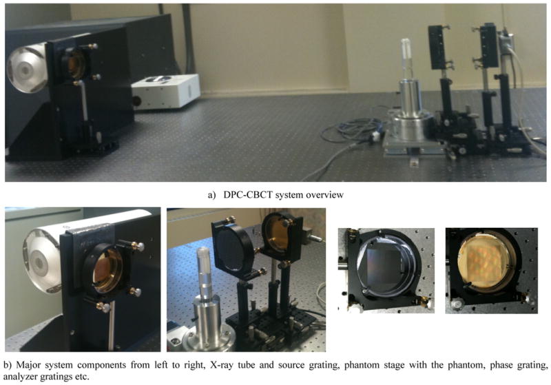
Bench-top DPC-CBCT system and components
The X-ray generating system is a Varian RAD70D Hospital grade X-ray tube (Varian Medical System, Salt Lake City, UT) with a nominal focal size of 0.3 mm. The generator was custom made at our request by Sedecal. A RadEye HR high resolution detector system (Rad-icon Imaging Corp, Santa Clara, CA), CMOS-based with a scintillator screen, is used to capture the X-ray images. The scintillator (made of Gd2O2S) of the chosen detector system is able to convert the X-ray photons to visible photons with a good spectrum response from 10keV to 90keV. It has a detector pitch of 22.5 μm, an active area of 36 mm × 27 mm, an image matrix of 1600 × 1200 and a dynamic range of 14 bits (~1:16000).
The major challenge in design and construction of the DPC-CBCT system is the fabrication and alignment of the gratings. Compared with gratings illustrated in our former paper, Y Yu, R Ning, and W. Cain, Proc. SPIE 7961-179(2011), the phase grating is enlarged to 5cm by 5cm with a designed period of 8 micron. The analysis grating is enlarged as well to 5cm by 5cm and has a designed period of 4.60 micron. The gratings are self-manufactured in the Cornell Nanofabrication facility via KOH chemical etching to achieve the desired grating structure, electroplating for the gold layer on the analysis grating, and etc.[16]. A source grating was also fabricated in the Cornell Nanofabrication facility, with a designed period of 30 micron.
Positioning of the gratings are demonstrated as in Fig. 1. The source grating is placed near the Hospital grade X-ray tube. The phase grating is mounted on a linear stage (VP-25XA, Newport, Irvine, CA) with a step accuracy of 0.1 μm, while the analyzer grating is placed close to the detector surface, and at the first fractional Talbot distance from the phase grating.
2.2 Phase retrieval method and reconstruction algorithm
The DPC-CBCT scan is done with 120 angles, each 3 degree apart from its neighbors. For each angle, a set of step images, typically 8, are acquired. The step images are then processed, i.e. phase retrieval, to generate the DPC images. The most common way of phase retrieval is based on discrete fourier transform, in which the phase information is retrieved by taking arctan of the quotient between the imaginary part and the real part of the first order discrete fourier transform component
Largely for the conveninence of FFT operation, 8 steps scheme is most commonly used when retrieving the phase information. Here, we introduce an interpolation based FFT phase retrieval method which enables us to accomplish a N (5<N<9) steps stepping scheme. While in a 8 steps scheme, steps images are taken at 8 positions by shifting the phase grating, equally distanced from its individual neighbors by 1/8 of the phase grating period, a N steps scheme would choose N positions from the 8 positions while acquiring the step images, yet still covering the 1 period distance. For example, in a 6 steps scheme, 1st, 3rd, 4th, 5th, 6th, and 8th, positions among the eight are chosen. A m-order (m=5) polynomial curve is then fitted to the samples, in order to generate a 8 points data set, which is then processed as in the 8 steps scheme with the 8-FFT. However, with the dose level in each step image fixed, compared with the 8 steps scheme, the dose level of a N (5<N<9) steps scheme for the DPC-CBCT scan is lowered by (8-N)/8.
The reconstruction of the object is then accomplished in the manner described below. With small the beam angle, thus the parallel beam assumption being valid, a filtered back-projection (FBP) algorithm[17] is be used for approximate reconstruction of the object. This reconstruction algorithm uses a Hilbert filter instead of the ramp filter as in the absorption based CT case, which can be formulated as:
| (1) |
where
| (2) |
2.3 Experiments Setup
With the hospital-grade X-ray tube-based bench top DPC-CBCT system set up, two investigations of the system performance were conducted. One aspect we pay special attenuation to is the dose efficiency, that is the system’s performance, i.e. CNR, corresponding to different dose levels. This is investigated via two approaches, (1) different dose levels in each step image while fixing the step scheme and (2) different phase step schemes while fixing the dose level allocated in each step image. One cylinder phantom was used in these investigations (Fig. 2). Physical dimensions of the phantom is as follows: The outer diameter of the cylinder is 25.4mm. The acrylic wall thickness is less than 2mm. The diameter of the inserted small cylinders is 7mm. The phase grating and the analyzer grating have to be aligned to manifest the best phase-contrast effect.
Fig. 2.
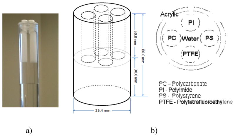
Design and image of the phantom
3. RESULTS
Fig. 3 demonstrates a typical DPC image and the corresponding reconstruction image of the phantom. The DPC images were retrieved using 8 steps scheme, while each step image was generated with 100mA, 40kVp, and 320ms (192mR).
Fig. 3.
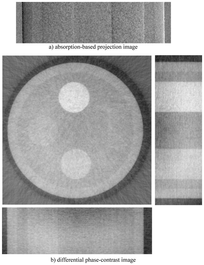
A typical DPC-CBCT phase retrieval imager, a) and its corresponding reconstruction image, b) (40 kVp, 100mA, 320ms, 120 projections, 8 steps)
In the following sections, two investigations with respect to the dose efficiency are conducted. Unlike absorption-based CT, due to the complexity of phase retrieval, DPC-CBCT has more than one way to alter the dose level of a scan. The dose level can at least be changed by 1) changing the dose level allocated in each step image, 2) using a fewer or more steps scheme while acquiring the DPC images. The corresponding investigations show different charateristics regarding the two ways of changing dose levels which are reported below.
3.1 Different dose level in each step image
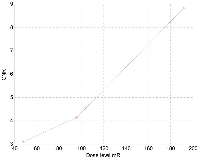
CNR is measured for PI against water. Noise is measured at 5 different areas in the image and averaged. It could be observed that as the dose level in each step image increases, CNR seems to follow a seemly exponential curve. The dose level however is changed without taking into consideration the steps scheme, that is to say the same steps scheme, e.g. 8, is used in all cases. Uniformity in the less dose cases are not as high as the high dose cases.
3.2 Different phase stepping schemes
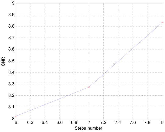
CNR is measured for PI against water. Noise is measured at 5 different areas in the image and averaged. It could be observed that as the more steps are used, CNR seems to increase almost linearly. It should be noticed however that dose as steps number increase linearly, that is to say 8 steps scheme naturally has 2/6 times more dose than a 6 steps scheme. Uniformity in fewer steps case seems constant with the 8 steps case.
A more comprehensive investigation regarding dose efficiency will be conducted in future study.
3.3 Compare attenuation image with phase contrast image
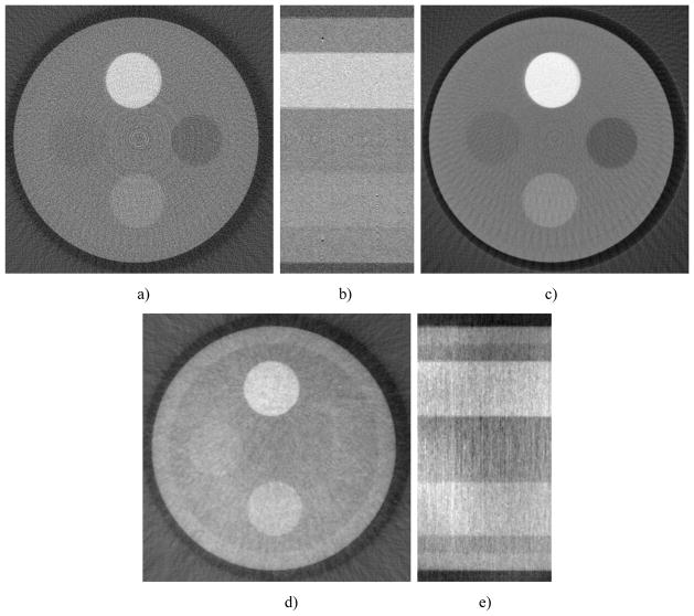
All contrast is measure versus water. Noise is measured at 4 different areas in the center of the images and averaged, normalized by the water coefficient of each image. For low dose cases, uniformity is not as high as the high dose cases. All measurements were taken from the axial view. It could be observed DPC-CBCT performs better than absorption-based imaging for certain materials (PI, PTFE). The most obvious is the inner wall of the phantom. While it is hardly visible in the absorption based reconstruction image, it could clearly be seen in the DPC reconstruction images even with less dosage. However, DPC-CBCT does not behave as well as absorption-based CT when imaging PS.
4. DISCUSSION AND CONCLUSION
We report here the design, construction, and performance evaluation of a bench-top differential phase-contrast cone beam CT (DPC-CBCT) system using a hospital-grade x-ray tube. The performance of the system was investigated via two approaches with the focus on dose efficiency. First, we investigated the system’s response in term of CNR to different dose levels used acquiring the step images (Fig. 4 and Fig. 5). It is found that as the dose level in each step increases, CNR increases seemly exponentially. Second, we investigated the system’s response in term of CNR to different phase stepping schemes. While 8 steps scheme is most commonly used in DPC imaging, it is possible to lower the dose of a DPC CT scan significantly by using a fewer steps scheme. In order to enable the use of M steps scheme, an interpolation based FFT phase retrieval method was implemented. It is observed that with fewer steps scheme, CNR decreases, though 7 and 6 steps schemes still offer similar advantages compared with 8 steps scheme to absorption-based imaging in CNR while imaging certain materials. (Fig. 6 and Fig. 7) The results of different step schemes are then compared with the absorption based result. (Fig. 8) CNR investigation suggest that phase contrast behaves better than absorption-based CT regarding certain materials. One significant advantage observable is the inner wall of the phantom, which while cannot be seen in the absorption-based reconstruction image, could be clearly observed in the DPC based reconstruction images, even with less dosage. Phase contrast also yields a higher contrast noise ratio under the dose level while imaging PI. However, DPC CBCT fails to match the absorption based CT regarding PS. As DPC-CBCT’s performance being material dependent, the value of DPC-CBCT for different applications, is thus worth further investigation. Again, dose efficiency, that is the ideal allocation of dose with different stepping schemes and in each step image, will be investigated in future study.
Fig. 4.
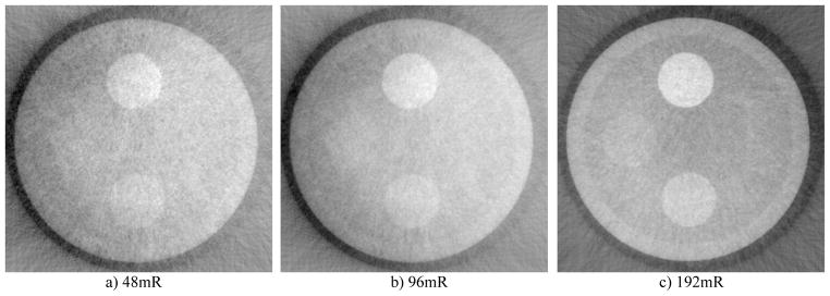
Comparison of DPC reconstruction images with different dose level in each step image
Fig. 5.
CNR vs. dose level
Fig. 6.
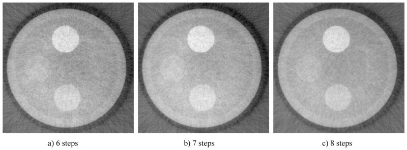
Comparison of DPC reconstruction images with different phase stepping scheme
Fig. 7.
Noise property vs. different steps scheme
Fig. 8.
DPC reconstruction vs. absorption based under the same dose level. Attenuation CBCT shows better contrast for PS (right insert). DPC-CBCT shows better contrast for the acrylic wall of the cylinder phantom, which begins to appear in the 32-slice averaged attenuation CBCT.
Table 2.
Contrast-noise-ration Comparison
| CNR-Acrylic | CNR-PS | |
|---|---|---|
| Absorption-based | NA | −4.66 |
| 8 steps DPC 100mA | 2.78 | NA |
| 7 steps DPC 100mA | 2.75 | NA |
| 6 steps DPC 100mA | 2.40 | NA |
| CNR-PC | CNR-PI | CNR-PTFE | |
|---|---|---|---|
| Absorption-based | −0.55 | 6.24 | 1 |
| 8 steps DPC 100mA | 3.85 | 8.87 | 7.07 |
| 7 steps DPC 100mA | 3.85 | 8.27 | 7.17 |
| 6 steps DPC 100mA | 3.73 | 8.02 | 6.67 |
Acknowledgments
This project was supported in part by NIH Grant R01 CA 143050. David Conover is an employee of Koning Corporation. Ruola Ning is a consultant to, equity holder and President of Koning Corporation during the study. Koning Corporation has licensed several patents from the University of Rochester, and seeks to commercialize medical imaging equipment utilizing the cone bean CT technology. The University of Rochester holds a small equity interest in Koning. Part of this work was performed at the Cornell NanoScale Facility (CNF), a member of the National Nanotechnology Infrastructure Network, which is supported by the National Science Foundation (Grant ECS 0335765).
References
- 1.Momose A. Demonstration of phase-contrast X-ray computed tomography using an X-ray interferometer. Nucl Instr And Meth In Phys Res A. 1995;352:622–628. [Google Scholar]
- 2.Takeda T, Momose A, Wu J, Yu Q, Zeniya T, Lwin T, Yoneyama A, Itai Y. Vessel Imaging by interferometric phase-contrast X-ray technique. Circulation. 2002 Apr 9;:1708–1712. doi: 10.1161/01.cir.0000012752.35225.6c. [DOI] [PubMed] [Google Scholar]
- 3.Momose A, Takeda T, Itai Y. Phase-contrast X-ray computed tomography for observing biological specimens and organic materials. Rev Sci Instrum. 1995;66(2):1434–1436. [Google Scholar]
- 4.Chapman D, Thomlinson W, Johnston RE, Washburn D, Pisano E, Gmur N, Zhong Z, Menk R, Arfelli F, Sayers D. Diffraction enhanced X-ray imaging. Phys Med Biol. 1997;42:2015–2025. doi: 10.1088/0031-9155/42/11/001. [DOI] [PubMed] [Google Scholar]
- 5.Dilmanian FA, Zhong Z, Ren B, Wu XY, Chapman LD, Orion I, Thomlinson WC. Computed tomography of X-ray index of refraction using the diffraction enhanced imaging method. Phys Med Biol. 2000;45:933–946. doi: 10.1088/0031-9155/45/4/309. [DOI] [PubMed] [Google Scholar]
- 6.Chou C, Anastasio M, Brankov J, Wernick M, Brey E, Connor E, Jr, Zhong Z. An extended diffraction-enhanced imaging method for implementing multiple-image radiography. Phys Med Biol. 2007;52:1923–1945. doi: 10.1088/0031-9155/52/7/011. [DOI] [PubMed] [Google Scholar]
- 7.Snigirev A, Snigireva I, Kohn V, Kuznetsov S, Schelokov I. On the possibilities of X-ray phase contrast microimaging by coherent high-energy synchrotron radiation. Rev Sci Instrum. 1995;66(12):5486–5492. [Google Scholar]
- 8.Wilkins SW, Gureyev TE, Gao D, Pogany A, Stevenson AW. Phase-contrast imaging using polychromatic hard X-rays. Nature. 1996;384:335–338. [Google Scholar]
- 9.Wu X, Liu H, Yan A. X-ray phase-attenuation duality and phase retrieval. Optics Letters. 2005;30:379–381. doi: 10.1364/ol.30.000379. [DOI] [PubMed] [Google Scholar]
- 10.Pfeiffer F, Weitkamp T, Bunk O, David C. Phase retrieval and differential phase-contrast imaging with low-brilliance X-ray sources. Nature Physics. 2006;2:258–261. [Google Scholar]
- 11.Kottler C, Pfeiffer F, Bunk O, Grunzweig C, Bruder J, Kaufmann R, Tlustos L, Walt H, Briod I, Weitkamp T, David C. Phase contrast X-ray imaging of large samples using an incoherent laboratory source. Phys Stat Sol A. 2007;204(8):2728–2733. [Google Scholar]
- 12.Pfeiffer F, David C, Bunk O, Donath T, Bech M, Le Duc G, Bravin A, Cloetens P. Region-of-interest tomography for grating-based X-ray differential phase-contrast imaging. Phys Rev Lett. 2008;101:168101. doi: 10.1103/PhysRevLett.101.168101. [DOI] [PubMed] [Google Scholar]
- 13.Cai W, Ning R. Dose efficiency consideration for volume-of-interest breast imaging using X-ray differential phase-contrast CT. Proc SPIE. 2009;7258:72584D. [Google Scholar]
- 14.Cai W, Ning R. Design and Construction of a Micro-focus In-line Phase-contrast Cone Beam CT (PC-CBCT) System for Soft Tissue Imaging. Proc SPIE. 2010;7622:76225F. [Google Scholar]
- 15.Yu Y, Ning R, Cai W. Performance Evaluation of a Differential Phase-contrast Cone-beam (DPC-CBCT) System for Soft Tissue Imaging. Proc SPIE. 2011;7961:79614X. doi: 10.1117/12.878492. [DOI] [PMC free article] [PubMed] [Google Scholar]
- 16.David C, Bruder J, Rohbeck T, Grunzweig C, Kottler C, Diaz A, Bunk O, Pfeiffer F. Fabrication of diffraction gratings for hard X-ray phase contrast imaging. Microelectronic Eng. 2007;84:1172–1177. [Google Scholar]
- 17.Faris Gregory W, Byer Robert L. Three-dimensional beam-deflection optical tomography of a supersonic jet. Applied Optics. 1988;27(24):15. doi: 10.1364/AO.27.005202. [DOI] [PubMed] [Google Scholar]


