

Abstract
Fluorescence image guided surgery (FIGS) allows intraoperative visualization of critical structures, with applications spanning neurology, cardiology and oncology. An unmet clinical need is prevention of iatrogenic nerve damage, a major cause of post-surgical morbidity. Here we describe the advancement of FIGS imaging hardware, coupled with a custom nerve-labeling fluorophore (GE3082), to bring FIGS nerve imaging closer to clinical translation. The instrument is comprised of a 405 nm laser and a white light LED source for excitation and illumination. A single 90 gram color CCD camera is coupled to a 10 mm surgical laparoscope for image acquisition. Synchronization of the light source and camera allows for simultaneous visualization of reflected white light and fluorescence using only a single camera. The imaging hardware and contrast agent were evaluated in rats during in situ surgical procedures.
Keywords: image-guided surgery, fluorescence imaging, contrast agent, nerve imaging
INTRODUCTION
Iatrogenic nerve damage is a major morbidity associated with surgical procedures including prostatectomy1–5, spinal cord fusion6,7, coronary artery bypass8,9, lumpectomy and mastectomy10,11. Complications arising from these injuries are dependent on the severity and location of the nerve injury but may result in loss of function and/or sensation, muscle atrophy, and chronic neuropathy12. The exact cause of nerve injury during laparoscopic and open surgical procedures is highly variable. However, inadvertent surgical damage due to poor visibility of nerves in comparison to surrounding tissue or simply the unfortunate necessity due to proximity of the nerve to target structures remains a constant risk. Currently employed nerve sparing techniques rely primarily upon anatomical landmark identification or use of intraoperative electrical stimulation devices to verify stimulation (via nerve) of innervated muscles or organs13,14. Surgical procedures are typically performed without any form of image guidance as the available technologies lack specificity needed to provide nerve-specific imaging15.
In the past ten years development in fluorescence image guided surgery (FIGS) has seen substantial preclinical activity and has led to several human clinical demonstrations16–18. The surgical technique consists of optical contrast agents matched with optical imaging hardware to provide visualization and increased contrast of otherwise indistinguishable anatomical features. Several recent reviews19–22 provide thorough overviews of hardware development, contrast agents and their applications. A range of targeted contrast agents have been used for tumor margin delineation23 and visualization of nerves24,25. Non-specific agents such as ICG have been used for locating sentinel lymph nodes in cancer surgeries16,18,21,26,27 and in vascular imaging17,28.
Presently optical imaging hardware for FIGS is seeing rapid development in functionality and miniaturization29–32, in order to provide clinical tools. Several companies are now marketing hand held FIGS devices (Fluobeam (www.fluoptics.com), O2view (www.o2view.com), and Hamamatsu16), though none are FDA approved. Minimally invasive surgery (MIS) is gaining prevalence because it offers benefits of small incisions, less pain, faster recovery, and fewer post-operative compilations. Robotic laparoscopic surgical systems such as the da Vinci Surgical System (Intuitive Surgical) are further advancing capabilities in specialized surgeries such as prostatectomy through finer precision and enhanced visualization. Until recently laparoscopic surgeries were performed using white light illumination and color digital cameras. FIGS techniques are an obvious enhancement to laparoscopic MIS procedures. Conventional laparoscopes have been outfitted with filtered illumination and filtered cameras to provide fluorescence guidance in pre-clinical procedures33,34 and clinical procedures17,18. Additionally, commercial laparoscopic systems are becoming available with integrated fluorescence imaging capabilities (Artemis camera system http://www.o2view.com/, da Vinci Surgical System Intuitive Surgical17).
Standard laparoscopes (10 mm or 5 mm diameter) have a large field of view (70–135 degrees) and small collection aperture (typically F/8 to F/12). FIGS imaging with laparoscopes faces specific challenges due low collection efficiencies and the requirement for compact and light weight equipment. The need for a light weight system precludes the use of sensitive, scientific grade cameras. In open surgical procedures a single channel system for fluorescence only may be suitable, as the surgeon can simply view the surgical area with their own eyes. However in MIS, a conventional white light image is a mandatory feature of any laparoscopic system. Presently, solutions to these challenges either manually switch between a white light and fluorescence image17,18,33 or provide a combined single image through leakage of the excitation light34. The limited efficiency of these systems may preclude using two simultaneous cameras split with a dichroic beam splitter or similar methods21,26,30. Several hybrid approaches to simultaneous multi-spectral imaging have been demonstrated for surgical imaging using reflected light. These involve multiple cameras and dichroics35, hybrid color cameras with custom filter mosaics36, fast liquid crystal tunable filters37 and modulated light sources coupled to the camera acquisition32,38.
In this work we present a solution to the problems outlined above in laparoscopic MIS. Here we have developed a simple, low cost, and light weight system that provides near simultaneous display of white-light and fluorescence images at VGA resolution. The system uses a single camera which allows for easy registration of the dual mode images for optional overlay and is compatible with any standard laparoscope. Here we use a standard 10mm zero degree laparoscope as is most widely used in MIS. A custom built illumination module is electronically synchronized to a single color camera that captures alternating white light and fluorescence images at 30 frames per second. This architecture allows for the maximum display frame rate and adaptability of the system to any camera. In this paper the capability of the system is demonstrated by imaging several types of in situ rat nerves via a nerve specific contrast agent GE3082 previously described27. Visualizing nerves in MIS is an important tool for several specialized surgical techniques where avoidance of nerves is critical to patient outcome. The absorption (400nm peak) and emission (broad band 500–700 nm) spectra of this agent is optimal for the dual imaging technique. Here the agent can be excited at the edge of the normal white spectrum (405 nm laser) and the emission can be collected over the same waveband as the white light images. The camera is only filtered by a single 405 nm laser line filter, thus allowing un-compromised white light reflectance imaging using an LED. Furthermore, the high quantum efficiency of the contrast agent affords high SNR images with minimal excitation power.
METHODS
1.1 Instrumentation
The imaging system consists of three primary modules: laparoscope, illumination, and control and acquisition. The laparoscope module comprises a 10mm zero degree surgical laparoscope with 70 degree field of view (T1000 Linvatec, Largo, FL), a 4mm diameter, 1800mm long laparoscope light guide (Medit Inc, Winnipeg Canada), a 35mm video coupler (MVC-35 Medit Inc, Winnipeg Canada), a compact 90 gram, 659×494 pixel color GigE camera (acA640-90gc Basler Ahrensburg Germany), and a 405nm blocking filter (BLP01-405R Semrock, Rochester, NY). The 1/3″ format sensor provides high sensitivity with 7.4 micron pixel size and adequate field of view (40 degrees out of 70 degrees passed by the laparoscope). The video coupler interfaces with the eyepiece of the laparoscope providing an interchangeable set up for different types of laparoscopes. The 405 nm filter is secured directly in front of the image sensor with a c-mount retaining ring. The analog camera threads onto the video coupler directly. The illumination light guide connects directly to each laparoscope with the appropriate mechanical coupler.
Illumination for white light and fluorescence imaging is coupled into a single light guide using conventional optics. Figure 1b shows the light coupling module. It consists of two 32 mm aspheric lenses (ACL4532, Thorlabs, Newton, NJ) to collimate a white light LED (XPGWHT-4-000-00H53 Cree Inc, Durham, NC) and a 500mW, 405nm blue laser diode coupled into a multimode fiber with 400 micron diameter (Shanghai Laser & Optics Century Co., Ltd., China). The LED spectrum is filtered with a 450 nm long pass filter (NT49-819 *discontinued, Edmund Optics, Barrington, NJ) to reduce the excitation of the fluorescent agent, while maintaining the white light color spectrum. The LED and laser are combined with a 425 nm dichroic mirror (DMLP425R, Thorlabs). The combined illumination is coupled into the light guide with a third 32 mm aspheric lens (ACL4532, Thorlabs). The maximum illumination from the LED is 2.0 mW/cm2 and 405 nm laser, 7.3 mW/cm2 at 25mm from the tip of the laparoscope. These laser powers represent class 3B operation when compared to the ANSI and IEC laser safety standards (ANZI Z136.1-2007, IEC 60825-1 2007) when eye exposure occurs at the laparoscope tip. When accidentally viewed from over 0.5 m, the diverging illumination hazard is well below class 1.
Figure 1.
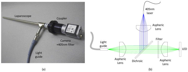
Details of the instrumentation. (a) Photograph of the laparoscope, coupler, camera with filter, and light guide. (b) Schematic of the illumination path. The LED and 405 nm laser are collimated and coupled into the light guide with aspheric lenses and combined with a dichroic mirror. A filter in the LED path filters the white light spectrum below 450 nm.
Electronic synchronization between the camera and illumination sources provides nearly simultaneous display of white light and fluorescence frames. Synchronization is achieved by triggering a 4 channel digital pulse generator (DG535, Stanford Research Systems, Inc, Sunnyvale, CA) with the output line of the GigE camera. The output line is specified in the camera setup file for “Exposure Active” which generates a 5V signal when the camera exposure is active. The camera acquisition is stopped and started from the PC, thus the illumination is automatically synchronized. The exposure active pulse is used to synchronize TTL pulses with pre-set delay and pulse width from the digital pulse generator. The stop and start time of each pulse is precisely aligned to ensure no bleed through to the opposing frames (see Figure 2a). The LED driver (D1B, Thorlabs) accommodates TTL input and provides LED illumination power control. The 405nm laser is modulated by a TTL input and power controlled by the laser driver. Raw interleaved camera frames are acquired using a modification of the example C++code supplied with the camera on a work station (Hewlett-Packard, xw8400, Palo Alto, CA). Images were adjusted for contrast and brightness in ImageJ (National Institutes of Health, Bethesda, MD).
Figure 2.

Timing diagram indicating synchronization between the camera and light sources. The camera synchronization signal (black) is used to drive the laser (red) and led (blue) modulation via a digital pulse generator.
1.2 Contrast and, animal preparation, and surgical imaging
Detailed optical characterization for GE3082 has been previously published27. All procedures were approved by the Institutional Animal Care and Use Committee (IACUC) at GE Global Research. Male Sprague-Dawley rats ranging in body weight from 250–300g were purchased from Charles River Laboratories (Wilmington, MA) and housed at 22–23°C on a 12-hour light/dark cycle. Rats were maintained on LabDiet 5001 rodent chow (LabDiet Framingham, MA) and water ad libitum. On the day of the experiment, rats were anesthetized using 2–4% isofluorane and given a single tail vein injection of either GE3082 (11 mg/kg) in formulation (0.5% DMSO, 35% Propylene Glycol, 35% Polyethylene Glycol 300, 18% 2-Hydroxypropyl β-cyclodextrin, 11.5% Sterile Water) or formulation buffer alone. The rats were then returned to the home cage and observed for potential health effects for 4-hrs following injection. After 4-hrs, rats were euthanized using compressed CO2 gas and key nerves (e.g. sciatic, brachial, supracapular, median, vagus) were exposed and imaged. In addition, a small incision was made below the sternum allowing for passage of the laparoscope into the closed thoracic cavity for phrenic nerve imaging.
RESULTS
Data was collected during a single imaging session consisting of a rat injected with GE3082 contrast agent and a rat injected with a formulation buffer only. Five different locations were imaged in the experimental rat. The range of locations demonstrates the extent of nerve labeling, taking into account nerves of differing sizes and myelination, and thus the overall imaging capability. Only the sciatic nerve was imaged in the control animal. The sciatic nerve is both the longest and widest single nerve in the periphery belonging to the “Type A fibers” of the Erlanger-Gasser scale39. As with other type A fibers, the sciatic nerve is heavily myelinated and thus lack of fluorescence emission in this nerve excludes staining throughout the periphery. After the procedure was complete, the same locations were imaged using a Zeiss SterREO Lumar Microscope in order to measure the physical dimensions of each nerve.
During imaging the room lighting was minimized in order to prevent light leakage during open imaging. The camera gain, laparoscope focus, and power of the LED and laser were adjusted to maximize image quality. The sciatic, brachial, median, vagus, and phrenic nerves were imaged using white light and fluorescence are shown in Figure 3. Nerve fluorescence was clearly visible in all nerves imaged and nerve identity was verified under white light conditions. This allowed for easy visualization of major nerve trunks and their divisions and associated cords. In Figure 3b2 the major trunk of the brachial plexus nerve is clearly seen spanning the length of the image. In addition fluorescence from smaller nerves such as the suprascapular (horizontal arrow in Figure 3b2) and even smaller diameter branches of the phrenic, radial, ulnar, and median nerves are also visible (light red arrow in Figure 3b2). Moreover, distinct borders of the nerves were clearly distinguishable from adjacent tissue and blood vessels in the fluorescence images. For example, in Figure 3d1, the vagus nerve is shown running parallel to the carotid artery and nearby trachea. In this image, distinct borders of the vagus are not easily defined along the entire length of the nerve in comparison to other adjacent tissue types. In contrast, using the fluorescence image Figure 3d2 the borders of the vagus are readily seen against the adjacent carotid artery and nearby trachea and thyroid gland. Similar findings were seen in the closed system imaging of the phrenic nerve. In Figure 3e1 the phrenic nerve is shown to be obscured by attached parietal pleura. However, in Figure 3d2 distinct fluorescence of the phrenic nerve is clearly seen along its entire length, regardless of the obscuring tissue seen in the white light image. Overall, these findings demonstrate visualization of nerves as small as 100 microns with high signal to noise both in open and minimally invasive conditions.
Figure 3.

Results from the GE3082 experimental rat. Column (1) white light, column (2) fluorescence, column (3) Zeiss Lumar microscope images with scale bar = 1mm. Row (a) sciatic nerve, (b) brachial, (c) median, (d) vagus, (e) phrenic. Arrows in column (2) show the location of primary nerves. Light red collared arrow in image (b2) show a nerve with 100 micron diameter.
The sciatic nerve of the control rat was imaged under the same illumination, imaging distance, and camera settings as the experimental rat. In Figures 4a and 4b the image histograms are displayed in the upper left corner showing no measureable signal in the fluorescence channel.
Figure 4.
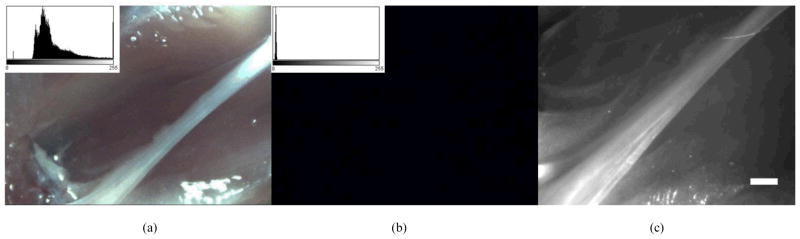
Results of control experiment. (a) White light image of control sciatic nerve (b) fluorescence image of control sciatic nerve. The image histogram is displayed in the upper left corner of 4a and 4b, showing no signal in the fluorescence channel. (c) Zeiss Lumar microscope image of the same image showing the size of the nerve. Scale bar is 1mm.
DISCUSSION
Reduction and prevention of nerve damage in surgery is an unmet clinical need requiring innovation in contrast agents as well as imaging hardware. A novel system incorporating both a contrast agent and fluorescence imaging instrumentation has been demonstrated. The instrumentation has been shown to provide simultaneous real time display of reflected white light and fluorescence images of nerves as small as 100 microns. Factors such as the excitation and emission spectra, utilization in a closed environment (as is present in minimally invasive surgery), advancement of light sources and available camera technology have made this dual mode imaging feasible using a combination of standard, low cost equipment. The promising imaging results obtained with the system using a visibly activated contrast agent suggest that absorption and emission in the visible spectrum may allow for high fidelity imaging in an intraoperative setting. Recently several works have demonstrated the advantages of NIR contrast agents for FIGS, because of its separation from the visible spectrum, reduced autofluorescence and prospects for deeper imaging penetration40,41. However, in controlled lighting situations such as MIS or with specialized room lighting, an agent excited at the blue end of the spectrum may also be advantageous. In particular, a highly specific, targeted fluorophore with a large Stokes shift can provide a high signal to background despite operating in the visible spectrum. Excitation at 405 nm allows for laser line rejection with minimal impact on white light image quality, and emission in the visible benefits from large detector quantum efficiency within this range. Furthermore, this approach is complementary to NIR imaging, and does not interfere with NIR fluorescence if multi-channel molecular imaging is desired25.
Acknowledgments
The authors thank Stephen Zingelewicz for software support. The project described was supported by award number 1R02EB022872-01 from the National Institute of Biomedical Imaging and Bioengineering. The content is solely the responsibility of the authors and does not necessarily represent the official views of the National Institute of Biomedical Imaging and Bioengineering or the National Institutes of Health.
References
- 1.Michaelson MD, Cotter SE, Gargollo PC, Zietman AL, Dahl DM, Smith MR. Management of complications of prostate cancer treatment. CA Cancer J Clin. 2008;58(4):196–213. doi: 10.3322/CA.2008.0002. [DOI] [PMC free article] [PubMed] [Google Scholar]
- 2.Graefen M, Walz J, Huland H. Open retropubic nerve-sparing radical prostatectomy. Eur Urol. 2006;49(1):38–48. doi: 10.1016/j.eururo.2005.10.008. [DOI] [PubMed] [Google Scholar]
- 3.Walz J, Graefen M, Huland H. Basic principles of anatomy for optimal surgical treatment of prostate cancer. World J Urol. 2007;25(1):31–38. doi: 10.1007/s00345-007-0159-6. [DOI] [PubMed] [Google Scholar]
- 4.Deyo RA, Gray DT, Kreuter W, Mirza S, Martin BI. United States trends in lumbar fusion surgery for degenerative conditions. Spine. 2005;30(12):1441–1445. doi: 10.1097/01.brs.0000166503.37969.8a. discussion 1446–1447. [DOI] [PubMed] [Google Scholar]
- 5.Olmarker K, Kiuchi S, Rydevik B. Anatomy and physiology of spinal nerve roots and the results of compression and irritation. In: Giles LGF, Singer KP, editors. Clinical Anatomy and the Management of Low Back Pain. Vol. 1. Edinburgh: Butterworth-Heinemann; 1997. pp. 243–253. [Google Scholar]
- 6.Bruce J, Drury N, Poobalan AS, Jeffrey RR, Smith WC, Chambers WA. The prevalence of chronic chest and leg pain following cardiac surgery: a historical cohort study. Pain. 2003;104(1–2):265–273. doi: 10.1016/s0304-3959(03)00017-4. [DOI] [PubMed] [Google Scholar]
- 7.Sharma AD, Parmley CL, Sreeram G, Grocott HP. Peripheral nerve injuries during cardiac surgery: risk factors, diagnosis, prognosis, and prevention. Anesth Analg. 2000;91(6):1358–1369. doi: 10.1097/00000539-200012000-00010. [DOI] [PubMed] [Google Scholar]
- 8.Aluffi P, Policarpo M, Cherovac C, Olina M, Dosdegani R, Pia F. Post-thyroidectomy superior laryngeal nerve injury. Eur Arch Otorhinolaryngol. 2001;258(9):451–454. doi: 10.1007/s004050100382. [DOI] [PubMed] [Google Scholar]
- 9.Cooper DS. Thyroxine monotherapy after thyroidectomy: coming full circle. Jama. 2008;299(7):817–819. doi: 10.1001/jama.299.7.817. [DOI] [PubMed] [Google Scholar]
- 10.Macdonald L, Bruce J, Scott NW, Smith WC, Chambers WA. Long-term follow-up of breast cancer survivors with post-mastectomy pain syndrome. Br J Cancer. 2005;92(2):225–230. doi: 10.1038/sj.bjc.6602304. [DOI] [PMC free article] [PubMed] [Google Scholar]
- 11.Poleshuck EL, Katz J, Andrus CH, Hogan LA, Jung BF, Kulick DI, Dworkin RH. Risk factors for chronic pain following breast cancer surgery: a prospective study. J Pain. 2006;7(9):626–634. doi: 10.1016/j.jpain.2006.02.007. [DOI] [PMC free article] [PubMed] [Google Scholar]
- 12.Peters TM. Image-guidance for surgical procedures. Phys Med Biol. 2006;51(14):R505–540. doi: 10.1088/0031-9155/51/14/R01. [DOI] [PubMed] [Google Scholar]
- 13.Rehman J, Christ GJ, Kaynan A, Samadi D, Fleischmann J. Intraoperative electrical stimulation of cavernosal nerves with monitoring of intracorporeal pressure in patients undergoing nerve sparing radical prostatectomy. BJU Int. 1999;84(3):305–310. doi: 10.1046/j.1464-410x.1999.00143.x. [DOI] [PubMed] [Google Scholar]
- 14.Costello AJ, Brooks M, Cole OJ. Anatomical studies of the neurovascular bundle and cavernosal nerves. BJU Int. 2004;94(7):1071–1076. doi: 10.1111/j.1464-410X.2004.05106.x. [DOI] [PubMed] [Google Scholar]
- 15.Katahira A, Niikura H, Kaiho Y, Nakagawa H, Kurokawa K, Arai Y, Yaegashi N. Intraoperative electrical stimulation of the pelvic splanchnic nerves during nerve-sparing radical hysterectomy. Gynecol Oncol. 2005;98(3):462–466. doi: 10.1016/j.ygyno.2005.05.004. [DOI] [PubMed] [Google Scholar]
- 16.Tagaya N, Nakagawa A, Abe A, Iwasaki Y, Kubota K. Non-invasive identification of sentinel lymph nodes using indocyanine green fluorescence imaging in patients with breast cancer. Open Surg Oncol J. 2010;2:71–74. [Google Scholar]
- 17.Tobis S, Knopf J, Silvers C, Yao J, Rashid H, Wu G, Golijanin D. Near infrared fluorescence imaging with robotic assisted laparoscopic partial nephrectomy: initial clinical experience for renal cortical tumors. J Urol. 2011;186:47–52. doi: 10.1016/j.juro.2011.02.2701. [DOI] [PubMed] [Google Scholar]
- 18.van der Poel HG, Buckle T, Brouwer OR, Valdés Olmos RA, van Leeuwen FWB. Intraoperative laparoscopic fluorescence guidance to the sentinel lymph node in prostate cancer patients: Clinical proof of concept of an integrated functional imaging approach using a multimodal tracer. Eur Urol. 2011;60:826–833. doi: 10.1016/j.eururo.2011.03.024. [DOI] [PubMed] [Google Scholar]
- 19.Ntziachristos V, Yoo JS, van Dam GM. Current concepts and future perspectives on surgical optical imaging in cancer. J Biomed Opt. 2010;15(6):066024. doi: 10.1117/1.3523364. [DOI] [PubMed] [Google Scholar]
- 20.Pogue BW, Gibbs-Strauss SL, Valdés PA, Samkoe KS, Roberts DW, Paulsen KD. Review of neurological fluorescence imaging methodologies. IEEE J Sel Top Quantum Electron. 2010;16:493–505. doi: 10.1109/JSTQE.2009.2034541. [DOI] [PMC free article] [PubMed] [Google Scholar]
- 21.Gioux S, Choi HS, Frangioni JV. Image-guided surgery using invisible near-infrared light: fundamentals of clinical translation. Mol Imaging. 2010;9(5):237–255. [PMC free article] [PubMed] [Google Scholar]
- 22.Keereweer S, Kerrebijn JDF, van Driel PBAA, Xie B, Kaijzel EL, Snoeks TJA, Que I, Hutteman M, Van der Vorst JR, Mieog JSD, Vahrmeijer AL, Van de Velde CJH, Baatenburg de Jong RJ, Löwik CWGM. Optical image guided surgery--Where do we stand? Mol Imaging Biol. 2011;13:199–207. doi: 10.1007/s11307-010-0373-2. [DOI] [PMC free article] [PubMed] [Google Scholar]
- 23.Mieog JSD, Vahrmeijer AL, Hutteman M, van der Vorst JR, van Hooff MD, Dijkstra J, Kuppen PJK, Keijzer R, Kaijzel EL, Que I, van de Velde CJH, Löwik CWGM. Novel intraoperative near-infrared fluorescence camera system for optical image-guided cancer surgery. Mol Imaging. 2010;9:223–231. [PubMed] [Google Scholar]
- 24.Whitney MA, Crisp JL, Nguyen LT, Friedman B, Gross LA, Steinbach P, Tsien RY, Nguyen QT. Fluorescent peptides highlight peripheral nerves during surgery in mice. Nat Biotechnol. 2011;29(4):352–356. doi: 10.1038/nbt.1764. [DOI] [PMC free article] [PubMed] [Google Scholar]
- 25.Gibbs-Strauss SL, Nasr KA, Fish KM, Khullar O, Ashitate Y, Siclovan TM, Johnson BF, Barnhardt NE, Tan Hehir CA, Frangioni JV. Nerve-highlighting fluorescent contrast agents for image-guided surgery. Mol Imaging. 2011;10:91–101. [PMC free article] [PubMed] [Google Scholar]
- 26.Troyan SL, Kianzad V, Gibbs-Strauss SL, Gioux S, Matsui A, Oketokoun R, Ngo L, Khamene A, Azar F, Frangioni JV. The FLARETM intraoperative near-infrared fluorescence imaging system: A first-in-human clinical trial in breast cancer sentinel lymph node mapping. Ann Surg Oncol. 2009;16:2943–2952. doi: 10.1245/s10434-009-0594-2. [DOI] [PMC free article] [PubMed] [Google Scholar]
- 27.Crane LM, Themelis G, Pleijhuis RG, Harlaar NJ, Sarantopoulos A, Arts HJ, van der Zee AG, Ntziachristos V, van Dam GM. Intraoperative multispectral fluorescence imaging for the detection of the sentinel lymph node in cervical cancer: a novel concept. Mol Imaging Biol. 2011;13(5):1043–1049. doi: 10.1007/s11307-010-0425-7. [DOI] [PMC free article] [PubMed] [Google Scholar]
- 28.De Grand AM, Frangioni JV. An operational near-infrared fluorescence imaging system prototype for large animal surgery. Technol Cancer Res Treat. 2003;2(6):553–562. doi: 10.1177/153303460300200607. [DOI] [PubMed] [Google Scholar]
- 29.Kakareka JW, McCann TE, Kosaka N, Mitsunaga M, Morgan NY, Pohida TJ, Choyke PL, Kobayashi H. A portable fluorescence camera for testing surgical specimens in the operating room: description and early evaluation. Mol Imaging Biol. 2011;13(5):862–867. doi: 10.1007/s11307-010-0438-2. [DOI] [PMC free article] [PubMed] [Google Scholar]
- 30.Wang X, Bhaumik S, Li Q, Staudinger VP, Yazdanfar S. Compact instrument for fluorescence image guided surgery. J Biomed Opt. 2010;15:020509. doi: 10.1117/1.3378128. [DOI] [PubMed] [Google Scholar]
- 31.Liu Y, Bauer AQ, Akers WJ, Sudlow G, Liang K, Shen D, Berezin MY, Culver JP, Achilefu S. Hands-free, wireless goggles for near-infrared fluorescence and real-time image-guided surgery. Surgery. 2011;149:689–698. doi: 10.1016/j.surg.2011.02.007. [DOI] [PMC free article] [PubMed] [Google Scholar]
- 32.Sun R, Bouchard MB, Hillman EMC. SPLASSH: Open source software for camera-based high-speed, multispectral in-vivo optical image acquisition. Biomed Opt Express. 2010;1(2):385–397. doi: 10.1364/BOE.1.000385. [DOI] [PMC free article] [PubMed] [Google Scholar]
- 33.Adusumilli PS, Eisenberg DP, Stiles BM, Chung S, Chan MK, Rusch VW, Fong Y. Intraoperative localization of lymph node metastases with a replication-competent herpes simplex virus. J Thorac Cardiovasc Surg. 2006;132(5):1179–1188. doi: 10.1016/j.jtcvs.2006.07.005. [DOI] [PubMed] [Google Scholar]
- 34.Tran Cao HS, Kaushal S, Lee C, Snyder CS, Thompson KJ, Horgan S, Talamini MA, Hoffman RM, Bouvet M. Fluorescence laparoscopy imaging of pancreatic tumor progression in an orthotopic mouse model. Surg Endosc. 2011;25(1):48–54. doi: 10.1007/s00464-010-1127-6. [DOI] [PMC free article] [PubMed] [Google Scholar]
- 35.Themelis G, Yoo JS, Ntziachristos V. Multispectral imaging using multiple-bandpass filters. Opt Lett. 2008;33:1023–1025. doi: 10.1364/ol.33.001023. [DOI] [PubMed] [Google Scholar]
- 36.Kong L, Yi D, Sprigle S, Wang F, Wang C, Liu F, Adibi A, Tummala R. Single sensor that outputs narrowband multispectral images. J Biomed Opt. 2010;15(1):010502. doi: 10.1117/1.3277669. [DOI] [PMC free article] [PubMed] [Google Scholar]
- 37.Gebhart SC, Thompson RC, Mahadevan-Jansen A. Liquid-crystal tunable filter spectral imaging for brain tumor demarcation. Appl Opt. 2007;46(10):1896–1910. doi: 10.1364/ao.46.001896. [DOI] [PubMed] [Google Scholar]
- 38.Boudoux C, Yun SH, Oh WY, White WM, Iftimia NV, Shishkov M, Bouma BE, Tearney GJ. Rapid wavelength-swept spectrally encoded confocal microscopy. Opt Express. 2005;13:8214–8221. doi: 10.1364/opex.13.008214. [DOI] [PubMed] [Google Scholar]
- 39.Erlanger J, Gasser HS. The action potential in fibers of slow conduction in spinal roots and somatic nerves. Am J Physiol. 1930;92(1):43–82. [Google Scholar]
- 40.Frangioni JV. In vivo near-infrared fluorescence imaging. Curr Opin Chem Biol. 2003;7:626–634. doi: 10.1016/j.cbpa.2003.08.007. [DOI] [PubMed] [Google Scholar]
- 41.Sevick-Muraca EM, Rasmussen JC. Molecular imaging with optics: primer and case for near-infrared fluorescence techniques in personalized medicine. J Biomed Opt. 2008;13:041303. doi: 10.1117/1.2953185. [DOI] [PMC free article] [PubMed] [Google Scholar]