Abstract
Due to the need for high-resolution angiographic and interventional vascular imaging, a Micro-Angiographic Fluoroscope (MAF) detector with a Control, Acquisition, Processing, and Image Display System (CAPIDS) was installed on a detector changer, which was attached to the C-arm of a clinical angiographic unit at a local hospital. The MAF detector provides high-resolution, high-sensitivity, and real-time imaging capabilities and consists of a 300 µm-thick CsI phosphor, a dual stage micro-channel plate light image intensifier (LII) coupled to a fiber optic taper (FOT), and a scientific grade frame-transfer CCD camera, providing an image matrix of 1024×1024 35 µm effective square pixels with 12 bit depth. The changer allows the MAF region-of-interest (ROI) detector to be inserted in front of the Image Intensifier (II) when higher resolution is needed during angiographic or interventional vascular imaging procedures, e.g. endovascular stent deployment. The CAPIDS was developed and implemented using Laboratory Virtual Instrumentation Engineering Workbench (LabVIEW) software and provides a user-friendly interface that enables control of several clinical radiographic imaging modes of the MAF including: fluoroscopy, roadmapping, radiography, and digital-subtraction-angiography (DSA). The total system has been used for image guidance during endovascular image-guided interventions (EIGI) for diagnosing and treating artery stenoses and aneurysms using self-expanding endovascular stents and coils in fifteen patient cases, which have demonstrated benefits of using the ROI detector. The visualization of the fine detail of the endovascular devices and the vessels generally gave the clinicians confidence on performing neurovascular interventions and in some instances contributed to improved interventions.
Keywords: Neuro-imaging, neuro-endovascular image-guided interventions, x-ray imaging, fluoroscopic detector, high-resolution imaging
1. INTRODUCTION
Conventional X-ray Image Intensifiers (II), which typically have resolution of 3 lp/mm, may not meet the needs of angiographic and interventional vascular imaging for neurovascular procedures involving small vessels and devices, such as endovascular image-guided interventions (EIGI) with stents, which have a strut size of only 70 µm. We investigated a high resolution ROI MAF detector installed in front of the II detector to evaluate its use in neurovascular interventional procedures.
2. METHODS AND MATERIALS
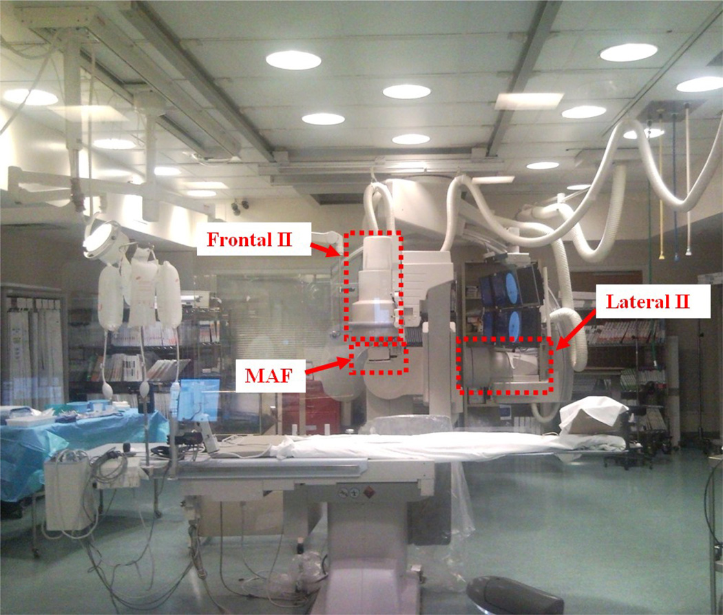
A region-of-interest (ROI) detector, the Micro-Angiographic Fluoroscope (MAF) was installed on a detector changer [1], which was attached to the frontal C-arm (Figure 1) of a Toshiba Infinix dual plane C-arm angiographic system having a 12-inch diameter II on each plane.
Figure 1.
Region-of-Interest (ROI) angiographic system at local university hospital
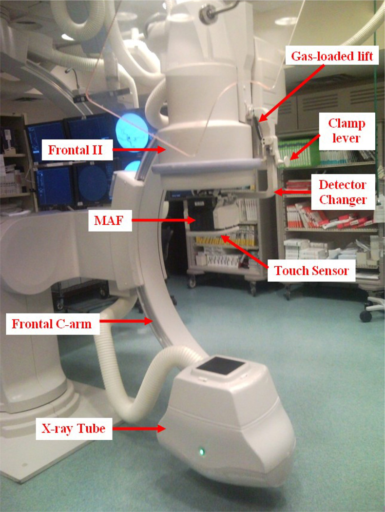
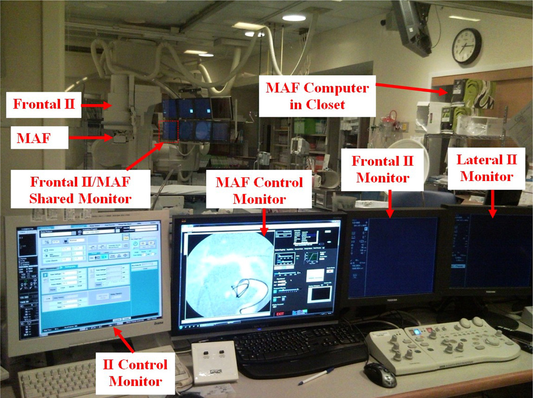
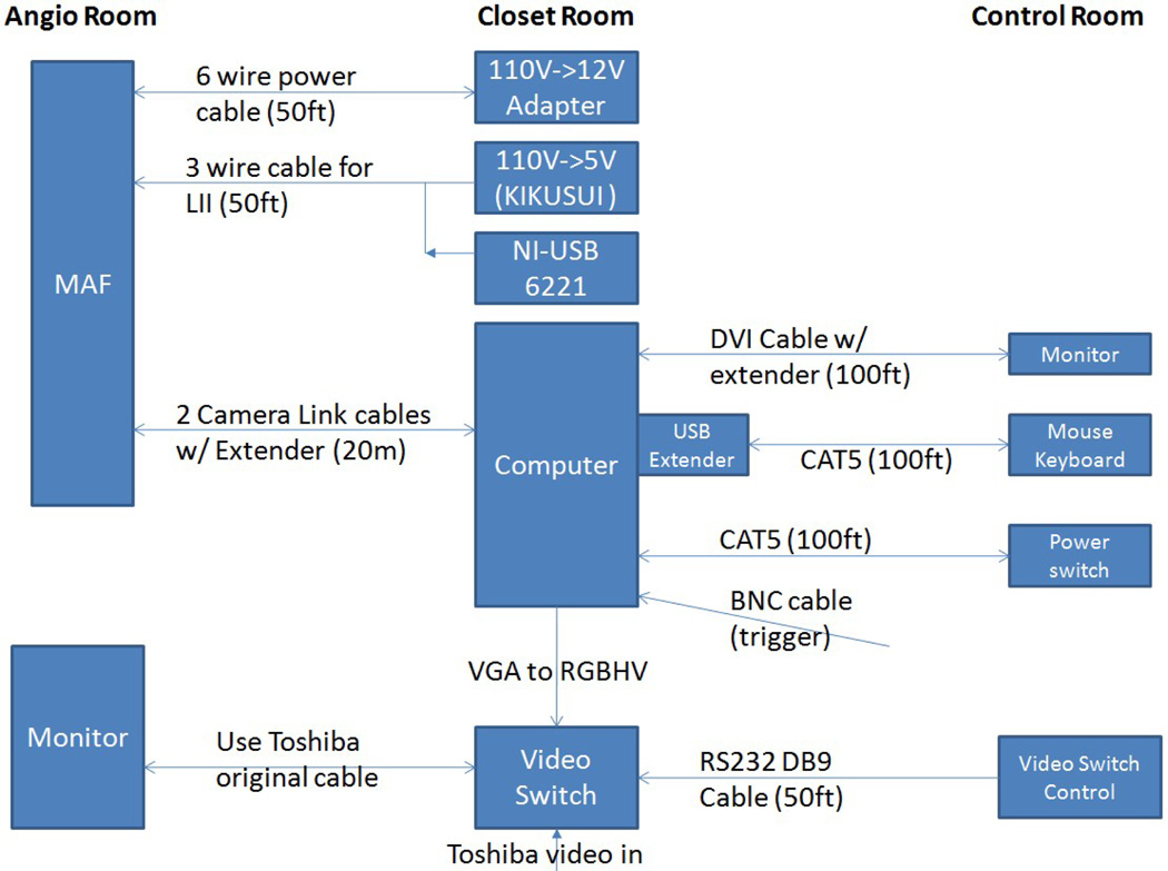
The MAF was controlled by custom-built software, CAPIDS [2,3,4]. A closer look at the deployed ROI detector system is shown in Figure 2. Figure 3 shows the control room view of the ROI system. The MAF control monitor is next to the II control monitor. Inside the angio room, the frontal II and the MAF share the lower left monitor of the monitor array since only one is used at any time. The MAF computer is inside the closet as indicated in Figure 3. The video switch, NI USB-6221 board (for adjusting the gain of the MAF), and the power supplies are also inside the closet shown in Figure 3. A detailed connection diagram is shown in Figure 4.
Figure 2.
ROI system, the MAF, installed at the university hospital.
Figure 3.
Control room view of the ROI system.
Figure 4.
ROI system instrumentation diagram.
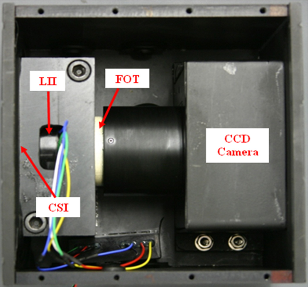
The MAF detector (Figure 5) consists of a 300 µm CsI phosphor; a dual-stage micro-channel plate Light Image Intensifier (LII) coupled to a 2.88:1 fiber-optic taper (FOT) and a fast-frame-rate, progressive-scan, frame-transfer CCD camera. The MAF detector's field of view is nominally 4 cm in diameter and it provides 1024×1024 pixels resolution with 35 micron pixel size and 12 bit depth for each pixel [5, 6]. A typical EIGI stent deployment for treating an aneurysm or stenosis using the ROI detector system proceeds as follows: 1. Before a patient enters the procedure room, the MAF is deployed and flat field images are acquired for different kVp settings, e.g. 80 kVp, 90 kVp, 100 kVp, etc. The flat field images were usually acquired around 7 AM before all the scheduled patient procedures. 2. Prior to using the MAF detector patient permission is obtained according to an approved Institutional Review Board protocol. 3. The neurosurgeons use the II under Roadmap mode to insert the guide wire and micro-catheters to the aneurysm location and use DSA mode to determine what kind of stent should be used and what size coils should be used to fill the aneurysm. 4. After the micro-catheter with undeployed stent is brought near the aneurysm location, the neurosurgeon requests the MAF detector to be deployed in front of the II detector, which typically takes less than one minute. Technique parameters are manually adjusted if necessary and a remote video switch (Figure 4) is used to transfer the MAF signal to the II/MAF shared monitor (Figure 3). 5. The stent and wires are deployed under the guidance of the MAF typically using the Roadmap mode or Roadmap mode with “display fluoro” selected. 6. DSA images are acquired using the II or MAF or both (not simultaneously) to evaluate the diverted blood flow with stent and wires in place.
Figure 5.
MAF detector.
3. RESULTS AND DISCUSSION
To date, fifteen human cases were performed using the MAF system for image guidance during endovascular image-guided interventions (EIGI) for diagnosing and treating artery stenoses and aneurysms using self-expanding endovascular stents and coils. The technique parameters of the 15 patients are shown in Table 1. Typically, patients received much less integral dose when using the MAF than when using the II because of the small field of view and because the output is limited using the small focal spot which is preferred for high-resolution imaging.
Table 1.
Human case summary
| # | Type | Detector | Procedure | Notes | |||||
|---|---|---|---|---|---|---|---|---|---|
| Fluoro | DSA | ||||||||
| kV | mA | ms | kV | mA | ms | ||||
| 1 | Arteriovenous malformation Follow up. |
II | 71 | 50 | 13.3 | 85 | 320 | 35 | |
| MAF | 71 | 50 | 13.3 | 85 | 160 | 25 | |||
| 2 | Aneurysm Follow up Coil |
II | 96 | 50 | 13.3 | 85 | 320 | 93 | |
| MAF | 90 | 50 | 10 | 86 | 160 | 41 | |||
| MAF HD | 80 | 160 | 20 | ||||||
| 80 | 160 | 6.3 | |||||||
| 3 | Aneurysm Initial Coil + Stent |
II | 110 | 50 | 13.3 | 85 | 320 | 93 | |
| MAF | 110 | 50 | 13.3 | 85 | 125 | 81 | |||
| MAF HD | 80 | 160 | 20 | ||||||
| 4 | Aneurysm Initial Coil + Stent |
II | 110 | 50 | 13.3 | 85 | 320 | 35 | |
| MAF | 90 | 50 | 10 | ||||||
| MAF HD | 80 | 160 | 20 | ||||||
| 5 | Aneurysm Initial Coil |
II | 85 | 50 | 13.3 | 85 | 320 | 98 | |
| MAF | 85 | 50 | 13.3 | 85 | 160 | 40 | |||
| 84 | 160 | 50 | |||||||
| 80 | 320 | 50 | MFS | ||||||
| 6 | Aneurysm Initial Coil |
II | 100 | 50 | 13.3 | 85 | 320 | 35 | |
| MAF | 100 | 50 | 13.3 | 85 | 160 | 25 | |||
| 7 | Aneurysm Initial Coil |
II | 87 | 50 | 13.3 15hz |
AP 97 | 320 | 85mfs | |
| 85 | 320 | 80 | |||||||
| MAF | 90 | 50 | 13.3 | 90 | 250 | 80 | |||
| MAF HD | 80 | 160 | 63 | ||||||
| 8 | Aneurysm Follow up Coil |
II | 73 | 50 | 13.3 | 85 | 320 | 78 | A |
| 71 | 50 | 13.3 | 85 | 320 | 35 | B | |||
| MAF | 73 | 50 | 13.3 | 85 | 320 | 86 | A | ||
| 90 | 250 | 100 | A | ||||||
| 71 | 50 | 13.3 | 85 | 160 | 25 | B | |||
| 9 | Aneurysm Initial Coil |
II | 77 | 50 | 13.3 | 97 | 125 | 77 | |
| MAF | 90 | 50 | 10 | 80 | 160 | 25 | |||
| 10 | Aneurysm Follow up Coil |
II | 76 | 50 | 13.3 | 110 | 100 | 100 | |
| MAF | 99 | 50 | 13.3 | 90 | 160 | 20 | |||
| 11 | Stenosis Initial Stent |
II | 110 | 49 | 13.3 | 85 | 320 | 35 | |
| MAF | 110 | 49 | 13.3 | 80 | 200 | 6.3 | MFS | ||
| 80 | 125 | 25 | SFS 15fps |
||||||
| 12 | Stenosis Initial Stent |
II | 88 | 50 | 13.3 | 85 | 320 | 88 | |
| MAF | 90 | 42 | 11 | 80 | 200 | 20 | SFS 15fps |
||
| 13 | Aneurysm Initial Coil |
II | 97 | 50 | 13.3 | 103 | 250 | 97 | |
| MAF | 97 | 50 | 13.3 | ||||||
| 14 | Aneurysm Initial Coil+ Stent |
II | 80 | 50 | 13.3 | 85 | 320 | 35 | |
| MAF | 90 | 50 | 13.3 | 85 | 160 | 25 | |||
| MAF HD | 80 | 160 | 12 | ||||||
| 80 | 160 | 25 | |||||||
| 15 | Stenosis Initial Balloon Angioplasty |
II | 85 | 50 | 13.3 | 85 | 320 | 86 | A |
| 80 | 50 | 13.3 | 85 | 320 | 35 | B | |||
| MAF | 85 | 50 | 13.3 | 90 | 250 | 63 | A | ||
| 80 | 50 | 13.3 | B | ||||||
| MAF HD | 80 | 125 | 12 | A | |||||
| 80 | 160 | 12 | 85 | 160 | 25 | B | |||
| 80 | 160 | 25 | B | ||||||
Notes:
1. For detector "HD" designates the MAF detector under high definition (HD) mode.
2. MFS refers to medium focal spot. SFS refers to small focal spot.
3. fps: frames per second.
4. The techniques used with the II for procedure segment A (or segment B) correspond to the techniques used with the MAF for segment A (or segment B). For example, for case #15, segment “A” for the II and the MAF used the same technique factors (85 kV, 50 mA, 13.3 ms).
5. AP, anterior posterior, refers to the Frontal II.
6. The technique parameters for MAF and II are selected to best reflect the response of the two detectors under similar conditions.
Six key cases are presented here which demonstrate the benefits of using the ROI MAF detector.
Case #2
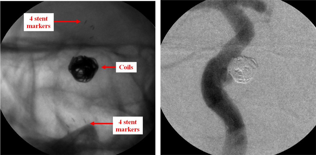
Patient case #2 is a follow-up case for checking an aneurysm previously treated with a stent and coils. The coils filled the aneurysm to stop blood flow into the aneurysm, and the stent prevented the coils from herniating out of the aneurysm. Both the stent and the coils are clearly visualized by using MAF detector (Figure 6, left). The pocket inside the aneurysm is clearly seen. Contrast was injected to visualize the modified flow during fluoroscopy, showing negligible flow getting into the aneurysm even though there is an unfilled pocket inside the aneurysm, which reconfirmed that the previous treatment was successful. A DSA run also reconfirmed the diverted flow (Figure 6, right).
Figure 6.
Patient case #2. Left: MAF fluoroscopy run (90 kV, 50 mA, 10 ms), stent and coil. Right: MAF DSA run (86 kV, 160 mA, 41 ms), diverted flow.
Case #4
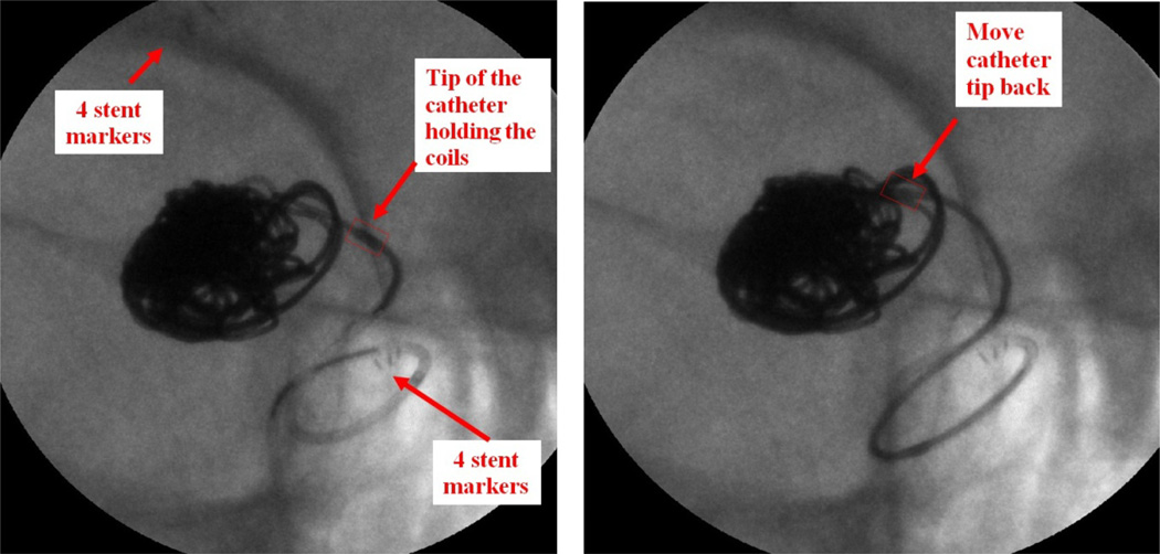
Patient case #4 (Figure 7) has a partially thrombosed P-com (posterior communicating artery) aneurysm. A stent and coils were used in this case.
Figure 7.
Patient Case #4: MAF Roadmap run with “display fluoro” selected (90 kV, 50 mA, 10 ms). Left: the tip of the catheter holding the coils was pushed back to the aneurysm neck; Right: Readjusting the position of the catheter tip towards the center of the aneurysm.
The procedure was done under MAF guidance. During the deployment of the coils, the tip of the catheter holding the coil was being pushed back towards the aneurysm neck; this was detected by the neurosurgeon and the catheter was inserted back into the center of the aneurysm. If the II were used, the tip movement might not have been noticed and could have caused the coil to have been dangerously deployed outside of the aneurysm.
Case #5
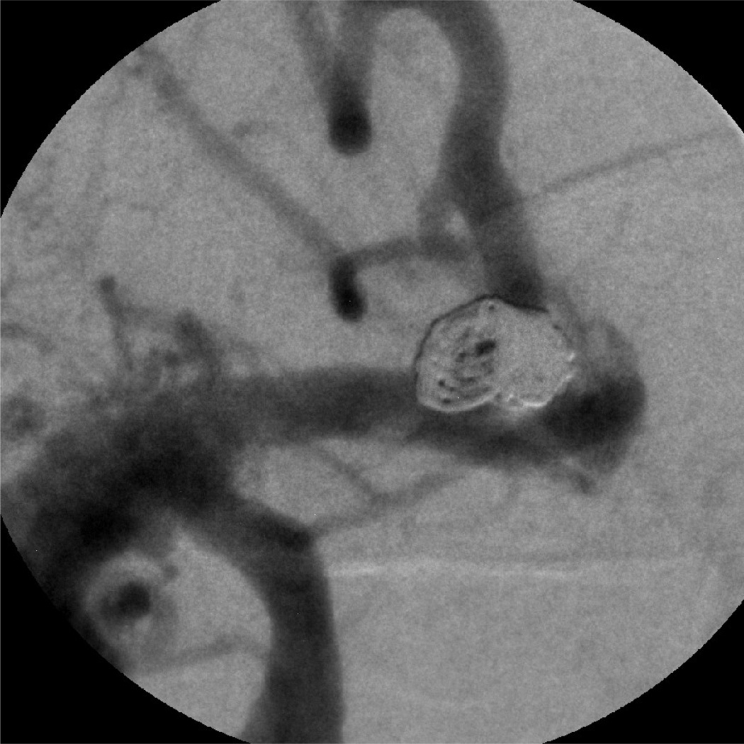
Patient case #5 (Figure 8) has a right middle cerebral artery (RMCA) occlusion and an A-com (anterior communicating artery) aneurysm. In this case, because of the high-resolution images provided by the MAF, the neurosurgeon decided that a stent was not needed to keep the coil inside the aneurysm. The MAF's high-resolution visualization saved the patient an expensive stent and a prolonged period on antiplatelet therapy (Plavix). High-resolution video sequences are available to illustrate in detail the successful use of the MAF.
Figure 8.
Patient Case #5, DSA (3 coils).
Case #7
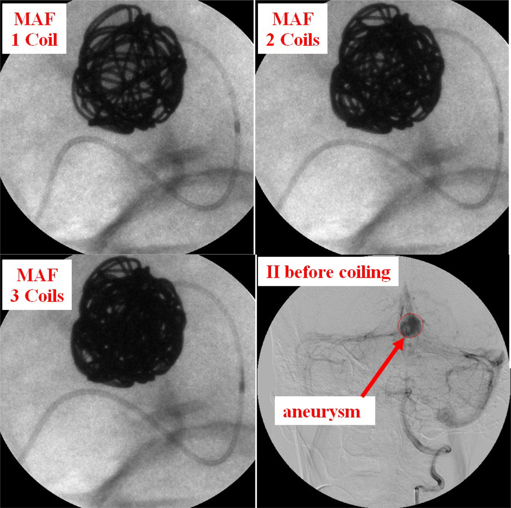
Patient case #7 was a giant aneurysm measuring 15.6 mm by 12.9 mm diameter. Three long coils were inserted into the aneurysm. The first coil was inserted using II imaging; the other 2 coils were inserted using the MAF. Figure 9 shows 1, 2, and 3 coils inside the aneurysm as well as the II DSA image before coiling. How the coil filled the aneurysm is visualized very clearly under the MAF's guidance. After the deployment of 3 long coils, the aneurysm was completely filled.
Figure 9.
Patient case #7: 1, 2, 3 coils inside aneurysm using the MAF Fluoro mode (90 kV, 50 mA, 13 ms) and the II DSA mode (85 kV, 320 mA, 80 ms) image before coiling.
Case #9
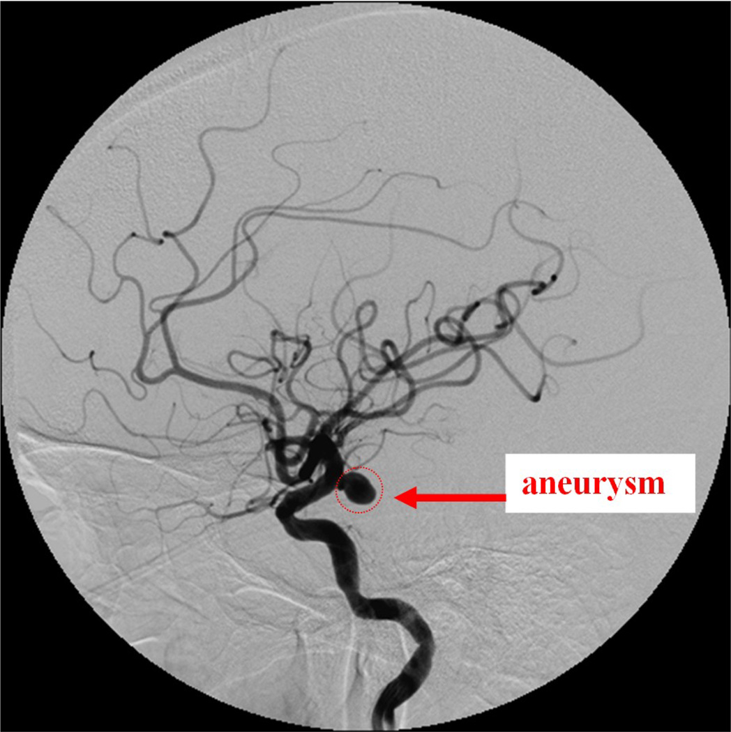
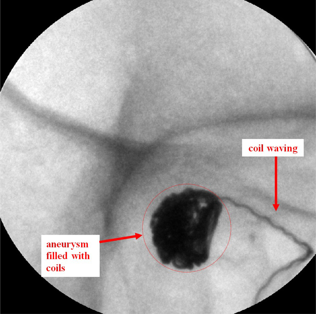
Patient case #9 was a heavy patient and there was a lot of patient movement during the procedure. The maximum diameter of the aneurysm, measured from the aneurysm neck to the dome, was 9.4 mm. A DSA angiogram taken using the II before the treatment is shown in Figure 10. Six coils were deployed inside the aneurysm. During the 4th coil deployment, the coil appears wavy inside the deployment catheter due to the pushing force applied on the coil (Figure 11).
Figure 10.
Patient case #9: II Angiogram showing the aneurysm (97 kV, 125 mA, 77 ms).
Figure 11.
Patient case #9: MAF fluoroscopy run, waving effect during the 4th coil deployment (90 kV, 50 mA, 10 ms).
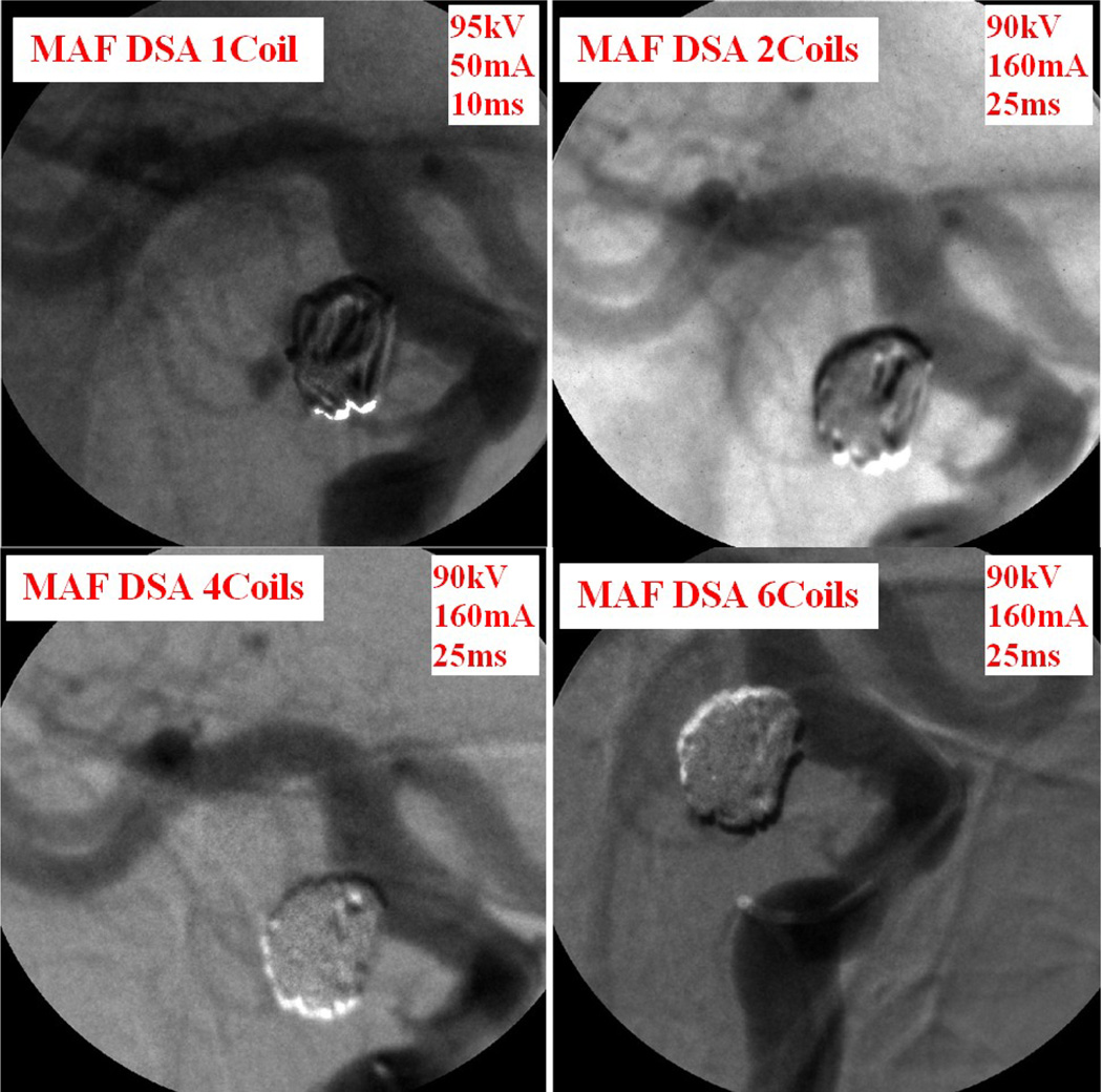
The "waving" effect could only be seen using the MAF and implies high force was applied to the wire, which should be avoided during the coil deployment. The neurosurgeon adjusted the force applied on the wire to avoid breaking the coil or rupturing the aneurysm. The whole coil was deployed inside the aneurysm after a couple of attempts. The high resolution MAF helped neurosurgeons to perform a more accurate and successful procedure. DSA images were taken during the procedure using the MAF to check the blood flow. Figure 12 shows the MAF DSA images taken after 1, 2, 4, and 6 coils were deployed inside the aneurysm. After just 1 or 2 coils were deployed, contrast was still visible in the DSA image. After 6 coils were deployed, there was negligible contrast flow inside the aneurysm.
Figure 12.
Patient case #9: DSA runs during the procedure.
Case #14
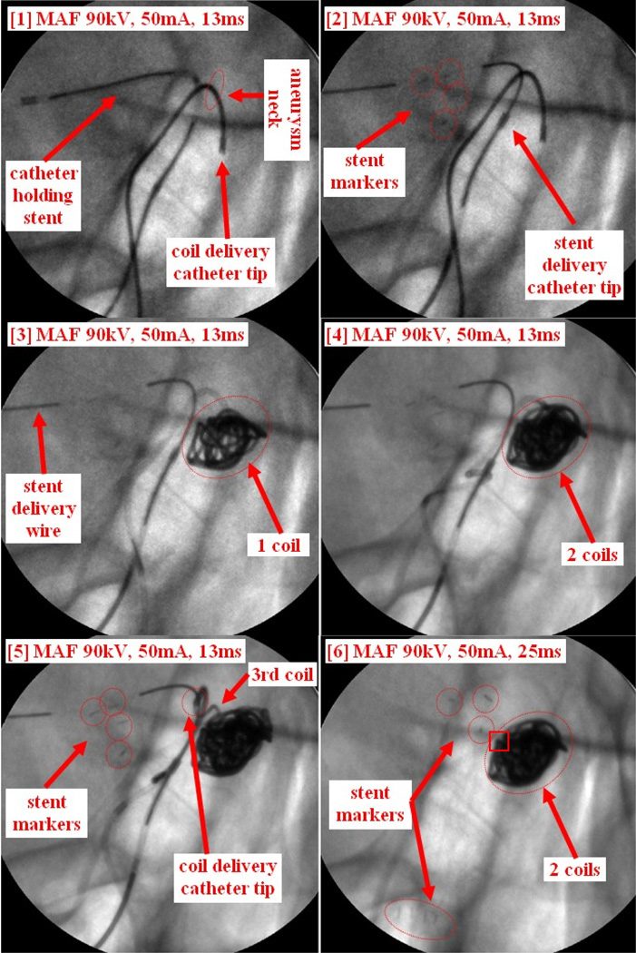
Patient case #14 is an aneurysm case. The plan was to partially deploy the stent to block the coils going into the main artery, and then deploy the coils before recapturing the stent. Due to the difficulties of recapturing the stent after deploying 2 coils, the stent was finally deployed. Figure 13 shows the whole procedure. The coil delivery catheter was first inserted inside the aneurysm, followed by inserting the coil to the tip of the coil delivery catheter (Figure 13-1). The catheter holding stent was also inserted (Figure 13-1). The stent was then partially deployed covering the aneurysm neck as shown in Figure 13-2. The distal markers of the stent are clearly visualized using the MAF (Figure 13-2). The 1st coil was then deployed inside of the aneurysm (Figure 13-3). An MAF DSA run was performed indicating contrast still goes into the aneurysm, which is not shown in Figure 13. A second coil was then inserted into the aneurysm (Figure 13-4) followed by another MAF DSA run. Even though the DSA looked very good, the neurosurgeon still wanted to insert another coil to further improve the filling. The neurosurgeon attempted to deploy the 3rd coil, but the coil could not be inserted completely; the waviness of the coil inside the delivery catheter showed that there was already too much force being applied to the coil. Finally the tip of the delivery catheter was inadvertently pushed outside of the aneurysm by the pressure of the coil as shown in Figure 13-5. Both the waving effect of the coil and the small movement of the catheter tip were not detectable by using the standard resolution II detector. The neurosurgeon decided to withdraw the 3rd coil. Two more MAF DSA runs were performed to make sure two coils were sufficient for this case. Next an attempt to withdraw the coil delivery catheter was made because there were no more coils to be delivered. The neurosurgeon then made multiple failed attempts to recapture the stent back into the stent delivery catheter. The MAF images indicated that the distal end of the stent was stuck on part of the coil mass (indicated by the square on Figure 13-6) a detailed feature not visualizable with an II. The stent delivery catheter could not be advanced to recapture the partially deployed stent. The stent was then deployed in the main artery as shown in Figure 13-6. Both the distal markers and the proximal markers are clearly visualized using the MAF.
Figure 13.
Patient case #14: coil and stent deployment.
4. CONCLUSIONS
The ROI system has been used during neuro-endovascular image-guided interventions (EIGI) for diagnosing and treating artery stenoses and aneurysms using self-expanding endovascular stents and coils in 15 patient cases. This experience has shown the substantial potential benefits of using the MAF ROI detector. Visualization of finer details of endovascular devices and vessels increased the confidence of neurosurgeons in performing neurovascular interventions. The full impact of the MAF toward improving the outcomes of EIGIs will be explored in future continuing studies.
ACKNOWLEDGEMENTS
This work was supported in part by the NIH Grants R01-EB008425, R01-EB002873, and equipment grant from Toshiba Medical Systems Corp.
REFERENCES
- 1.Wang Weiyuan, Keleshis C, Kuhls-Gilcrist A, Ionita C, Jain A, Bednarek D, Rudin S. New High-Resolution Detector Changer for a Clinical Fluoroscopic C-Arm Unit. Med. Phys. 2009;36:2474. [Google Scholar]
- 2.Keleshis Christos. PhD dissertation. SUNY at Buffalo: Electrical Engineering Department; 2009. Automated High Resolution, Micro-Angiographic Fluoroscopy Medical Systems. [Google Scholar]
- 3.Wang Weiyuan, Ionita C, Kuhls-Gilcrist A, Panse A, Bednarek D, Rudin S. WE-E-201C-07: The Upgraded Control, Acquisition, Processing, and Image Display System (CAPIDS) for a Micro-Angiographic Fluoroscope (MAF) Med. Phys. 2010;37:3440. [Google Scholar]
- 4.Wang Weiyuan, Ionita CN, Keleshis C, Kuhls-Gilcrist A, Jain A, Bednarek DR, Rudin S. Proceedings from Medical Imaging 2010: Physics of Medical Imaging. San Diego CA: Progress in the Development of a new Angiography Suite including the High Resolution Micro-Angiographic Fluoroscope (MAF), a Control, Acquisition, Processing, and Image Display System (CAPIDS), and a New Detector Changer Integrated into a Commercial C-Arm Angiography Unit to Enable Clinical Use. SPIE vol. 7622, 2010. paper 7622-200, 76225I:1-10. NIHMSID237867. https://www.pubmedcentral.gov/articlerender.fcgi?artid=3021378. [DOI] [PMC free article] [PubMed] [Google Scholar]
- 5.Yadava GK, Rudin S, Kuhls-Gilcrist AT, Bednarek DR. Generalized Objective Performance Assessment of a New High-Sensitivity Microangiographic Fluoroscopic (HSMAF) Imaging System. Proc. SPIE. 2008;6913 doi: 10.1117/12.769808. 69130U. [DOI] [PMC free article] [PubMed] [Google Scholar]
- 6.Ionita CN, Keleshis C, Patel V, Yadava G, Hoffmann KR, Bednarek DR, Jain A, Rudin S. Implementation of a high-sensitivity Micro-Angiographic Fluoroscope (HS-MAF) for in-vivo endovascular image guided interventions (EIGI) and region-of-interest computed tomography (ROI-CT) Proc. SPIE. 2008;6918 doi: 10.1117/12.770297. 69181I. [DOI] [PMC free article] [PubMed] [Google Scholar]


