Abstract
This work reports the ongoing development of a combination applicator for simultaneous heating of superficial tissue disease using a 915 MHz DCC (dual concentric conductor) array and High Dose Rate (HDR) brachytherapy delivered via an integrated conformal catheter array. The progress includes engineering design changes in the waterbolus, DCC configurations and fabrication techniques of the conformal multilayer applicator. The dosimetric impact of the thin copper DCC array is also assessed. Steady state fluid dynamics of the new waterbolus bag indicates nearly uniform flow with less than 1°C variation across a large (19×32cm) bolus. Thermometry data of the torso phantom acquired with computer controlled movement of fiberoptic temperature probes inside thermal mapping catheters indicate feasibility of real time feedback control for the DCC array. MR (magnetic resonance) scans of a torso phantom indicate that the waterbolus thickness across the treatment area is controlled by the pressure applied by the surrounding inflatable airbladder and applicator securing straps. The attenuation coefficient of the DCC array was measured as 3± 0.001% and 2.95±0.03 % using an ion chamber and OneDose™ dosimeters respectively. The performance of the combination applicator on patient phantoms provides valuable feedback to optimize the applicator prior use in the patient clinic.
Keywords: hyperthermia, brachytherapy, thermoradiotherapy, superficial disease, chestwall recurrence
1. INTRODUCTION
Breast cancer is the most common cancer in women with an estimated 200,000 new cases and a mortality of about 40,000 in 2005 in the United States of America [1]. The 5-year local control rate for stage III breast cancer treated with radiation and/or chemotherapy following surgery is reported to be 65% [2, 3] and the long term local-regional control varies between 40–50% [4–7]. The incidence of chest wall recurrence of breast cancer following surgery has been reported to vary between 5 and 35% [4, 6, 8–12]. The median survival rate for chest wall recurrence of breast cancer has been reported to be 2 years with a wide range in survival rate varying from few months to 30 years [13]. The wide variation in survival rate was attributed to lack of effective therapy techniques and failure to control local recurrence [14, 15]. The efficacy of heat on pronounced cell killing over 40–42.5°C has led to the development of hyperthermia devices for thermal therapy of cancer. Numerous devices employing microwave, radio frequency, laser and ultrasound energy sources have been developed to treat deep regional, whole body, interstitial and superficial tissue diseases [16, 17]. Several clinical trials have reported the effectiveness of hyperthermia treatment as an adjuvant therapy for local and superficial cancer treated with radiation and or chemotherapy including the chest wall recurrence of breast cancer [18–24]. Hyperthermia treatments delivered in combination with the standard radiation/chemotherapy treatment were observed to increase tumor response with a positive correlation between minimum thermal dose and improved tumor response [25]. The tumor response rate reported for single aperture planar waveguide type hyperthermia devices that treated lesions up to 3cm in diameter provided the motivation to develop multielement applicator arrays to expand tissue heating area and accommodate tissue heterogeneity. This led to the development of flexible conformal multielement array hyperthermia applicators for delivering thermal dose to large areas of superficial tissue disease spread over the typically contoured anatomy of the human torso [16, 17]. The conformal microwave array (CMA) applicator is one such device developed to treat large area superficial tissue disease spread over contoured patient anatomy as in chest wall recurrence of breast cancer [26]. The CMA employs an array of DCC slot antennas driven non-coherently at 915 MHz for most uniform heating of diffuse cutaneous disease located less than 2cm deep including the skin. The energy radiated by the DCC slot antenna array is coupled to the target tissue through a thin layer of temperature controlled degassed deionized water circulating though a 5–10 mm thick bolus. Tissue targets of complex shape and contour can be effectively irradiated by selectively switching on the individual DCC slot antennas. The energy radiated by individual DCC slot antennas is computer controlled using thermal feedback obtained from temperature probes inside the thermal mapping catheters on the tissue side of the water bolus bag.
There are indications in the literature that the efficacy of hyperthermia therapy for cancer can be significantly enhanced by delivering heat simultaneously with radiation/chemotherapy [18, 27, 28]. It has been shown in laboratory settings that the thermal enhancement ratio in tumor is much higher with concurrent delivery of heat and radiation than with sequential treatments. The potential benefits of increasing the thermal enhancement ratio from about 1.5 for sequential treatments to 2.5 or higher for simultaneous treatments have led to development of new combination applicators capable of simultaneous therapy [29–32]. One such applicator developed by this group for concurrent microwave heating and brachytherapy treatment of large area surface disease such as chest wall recurrence of breast cancer was reported in [32–33]. The combination applicator has the CMA applicator underneath an airbladder with an array of brachytherapy tubes on one side for delivering radiation to the target tissue from a single scanning HDR source. The last reports on the combination applicator in [32–33] documented the research carried out by the group at the University of California San Francisco. Ever since the last reports, efforts were focused on optimizing the individual components of the multilayer applicator for improved overall performance and compatibility with the HDR brachytherapy instrument currently used in the Radiation Oncology department at the Duke University Medical Center in Durham USA, where the PI moved in recent years. In this effort we present the progress on our ThermoBrachytherapy Surface Applicator (TBSA) and present preclinical evaluation studies performed on phantoms in a laboratory setting prior to its use in the patient clinic.
2. TBSA DESIGN IMPROVEMENTS
2.1 Waterbolus chamber
The waterbolus is one of the key components of the TBSA. In a typical hyperthermia treatment of superficial tissue disease such as chest wall recurrence of breast carcinoma, electromagnetic (EM) energy radiated by the applicator is transferred to the tissue through a thin layer of temperature controlled water. The deionized and degassed water circulating inside the bolus couples the EM energy into tissue and reduces spatial inhomogeneities in surface temperature during hyperthermia treatment. While allowing some compressability of the water layer to accommodate small irregularities of surface, the open cell filter foam inside the water bolus layer maintains a relatively fixed distance between the skin and the HDR radiation sources inside the brachytherapy tubing. Figure 1a shows a schematic of the bolus design that was used in early combination applicators. In Figure 1a, single inlet and outlet channels were used to feed deionized degassed water inside the bolus bag. The water in the inlet channel is dispersed into the bolus from the numerous openings in the feed channel and is collected inside the return tubing with perforated holes on the other end of the filter foam.
Fig. 1.
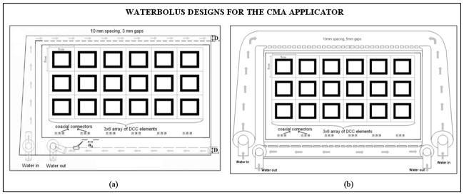
Schematic diagram of water bolus designs for the CMA applicator. (a) Single water inlet and outlet channels design used with earlier applicators [33] (b) New waterbolus design with wider dual opposing water inlet and outlet channels for improved flow distribution and high thermal transfer at the bolus tissue interface.
Uniform fluid flow pattern across the active bolus area is desired to maintain high thermal transfer at the bolus-tissue interface during hyperthermia treatment. However, momentum and friction effects along the fluid path affect the pressure distribution and flow rate inside the water inlet and outlet channels. Fluid dynamics simulations were performed to study pressure distributions inside the flow channels along the feed and return sides of the water bolus over the desired range of fluid flow rate. Fluid flow inside the bolus was analyzed using Comsol MultiPhysics (Comsol Inc., Boston, USA). Numerical simulations were performed while varying the dimensions of the inlet channel width (Ds), outlet tube diameter (Dr) and distribution orifice diameter (a0), as indicated in Figure 1a, and studying fluid flow patterns for dual opposing inlet and outlet channels. Based on the numerical simulations, a waterbolus design with larger diameter flow channels that feed water to the bolus from two sides (as shown in Figure 1b) was chosen for improved uniformity of fluid flow distribution across the bolus. Subsequently, a prototype PVC waterbolus bag with dual opposing flow channels was fabricated by Bionix Development Corporation.
2.2 DCC antenna configurations
Most of the original CMA applicator development used square slot DCC antennas fabricated on flexible printed circuit board (PCB) material for low profile and conformity to irregularly shaped disease over contoured surfaces such as the human torso. Numerous DCC antenna array designs varying from 2–5cm square apertures were studied radiating into complex loads at 915 MHz [34, 35]. Satisfactory numerical studies on the SAR and thermal distribution of the DCC arrays led to successful fabrication and eventually to use of the CMA applicator in preliminary clinical investigations. Figure 2(a) shows a 915 MHz square DCC slot antenna and its corresponding SAR pattern computed 5mm deep in muscle tissue. The regular square DCC slot antenna with microstrip feedlines across the center of each side slot forms the basic unit cell of the CMA array. The square DCC works well when the outline of the treatment area is rectangular such as in the main chest or back area but is less suitable to the perimeter of large CMA arrays that cover disease spreading around the armpit and neck area. In addition, as the area of the patch increases the overall power density decreases affecting the efficiency and the ability to deliver necessary thermal dose with a medium power amplifier (<50W). A large number of small efficient antennas is preferable as the disease is more accurately contoured and the lower power requirement for the amplifiers correlates with system reliability, durability, linearity and overall reduced cost. For these reasons, a set of design rules were developed to design efficient DCC slot antennas with other than square shape. While designing non-square slot antennas we implemented an additional design rule that reduced the area while increasing the perimeter of the slot, thus increasing antenna efficiency and power density in tissue. Figures 2(b)–(c) show non-square DCC slot antennas that were optimized to obtain conformal radiation pattern to treat regions under the arm and near the neck [26]. The EM numerical simulations were performed using a commercial package (HFSS, Ansoft Inc). The use of CMA applicators with square DCC elements in the central region and triangular or pentagonal DCC elements around the perimeter should provide improved coverage of the disease by eliminating the staircase effect of square arrays.
Fig. 2.
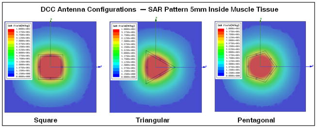
Three, four and five sided polygonal shaped DCC antenna configurations with corresponding SAR patterns from HFSS simulations, as optimized for conforming radiation patterns of 915 MHz CMA applicators to tissue disease that spreads in irregular shapes across the chest, around the neck and shoulder, and under the arm [26].
2.3 Applicator Layer Fabrication
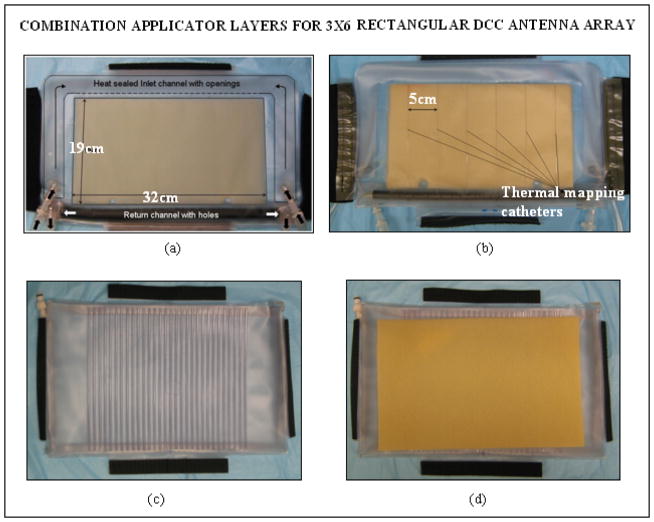
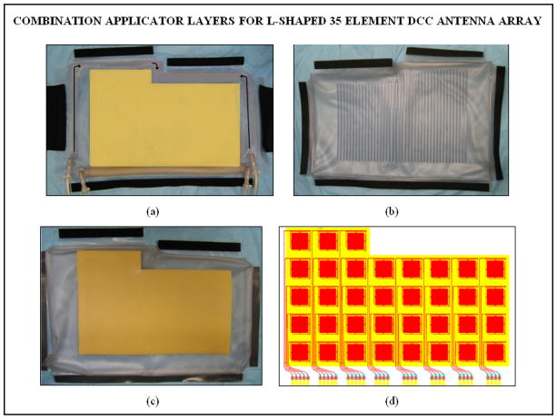
The multiple layers of PVC in the combination applicator were originally fabricated in the laboratory using an impulse heat sealing machine. Since then efforts were focused on devising robust and repeatable applicator fabrication techniques and devices for mass production of the multilayer combination applicator for housing both the heating and brachytherapy sources. The design efforts were carried out in cooperation with Bionix Development Corporation as part of an NIH SBIR grant. Thus recent fabrication and product assembly have been carried out by Bionix using RF induction sealing equipment that is more reproducible and robust than thermal heat seal closures. Figures 3 and 4 show layers of the rectangular and L-shaped combination applicators (respectively) fabricated by Bionix using medical grade polyvinylchloride (PVC) sheets that were heat sealed using an RF welding machine installed for this purpose. Each layer of the combination applicator including the thermal mapping catheters and brachytherapy tubing was fabricated using a welding template. Layers of PVC sheets were heat sealed in an orderly fashion for repeatable mass production. The thermal mapping catheters heat sealed to the waterbolus front (skin) surface are spaced such that surface temperatures can be measured along each column of DCC elements, including a temperature directly under the center of each element. The brachytherapy tubes secured to the airbladder are spaced 1cm apart to deliver radiation dose across the entire bolus area. Figure 5a shows the rectangular combination applicator on a torso phantom. The positioning of the individual conformal layers around the torso phantom is illustrated in Figure 5b. The layers can be secured around the patient anatomy using elastic straps and Velcro closures stitched to the individual layers.
Fig. 3.
New conformal layers of a rectangular combination applicator fabricated for the 3×6 DCC antenna array for treating the chest and back regions. (a) Waterbolus bag with (b) thermal mapping catheters sealed to the patient contacting side; (c) brachytherapy tubing attached to the air bladder for the scanning HDR radiation source; (d) dielectric spacer between HDR catheters and CMA.
Fig. 4.
New conformal layers of the L-shaped combination applicator fabricated for the 35 element DCC antenna array for treating the chest/back and shoulder regions. (a) Waterbolus bag with thermal mapping catheters sealed to the patient contacting side (b) brachytherapy tubes sealed to the air bladder to accept the scanning HDR radiation source; (c) dielectric spacer between the HDR source and CMA; (d) 35 element DCC array for use with the L-shaped applicator.
Fig. 5.
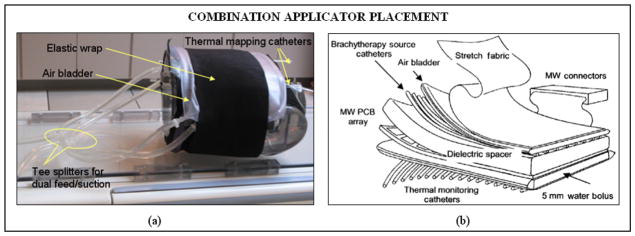
(a) The rectangular combination applicator wrapped on a torso phantom; (b) schematic illustrating the positioning of the individual layers of the combination applicator for thermoradiotherapy.
2.4 Performance Evaluation
Bolus Flow Dynamics
Steady state fluid flow dynamics of the water circulating inside the new rectangular waterbolus with dual opposing flow channels was empirically evaluated and compared with the earlier bolus design with single inlet and outlet flow channels. Sequential frames of thermal images recorded by an infra red (IR) camera for a step change in the circulating water temperature were used to assess the steady state fluid flow pattern of the newly fabricated and previously used waterbolus bags. Figure 6 shows the steady state fluid flow patterns of the earlier and newly fabricated waterbolus acquired using an infra red (IR) camera as the temperature of the circulating water was suddenly switched to a circulation system ~5°C above the initial temperature at steady state flow. Comparison of the fluid flow patterns clearly indicates an improved flow distribution with nearly uniform and straight flow across the new prototype waterbolus from the inlet to outlet channels. The thermal variation across the bolus surface at steady state temperature was observed to be within 1 and 1.5°C respectively for the new dual side and earlier single side feed bolus bags.
Fig. 6.

Steady state fluid flow patterns in the active bolus area acquired using an IR camera for a step change in the temperature of the water circulating inside the bolus at 2.21 liters per minute flow rate. Bolus bag placement (a, d) and bolus surface temperatures with superimposed thermal contours (b–c, e–f) captured using the IR camera illustrating the steady state flow patterns of the single side and dual channel waterbolus bags.
Thermal Mapping
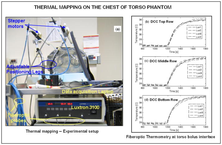
The feasibility of thermal mapping using the combination applicator on contoured anatomy was tested using a realistic shape phantom model of the human torso, as shown in Figure 5a. Thermometry on the torso phantom surface was carried out using a 4-channel fiber optic thermometry unit (Lupton 3100, Lamaze’s Technologies, Santa Clara, CA). Thermal mapping was performed using a stepper motor that precisely moved the fiberoptic probes back and forth along the catheter tracks at predetermined spatial intervals. Spatial displacements, dwell time at each position, and data acquisition from the Lupton thermometry unit were controlled using a Labview program (National Instruments Corp., Austin TX). For the thermal mapping experiment, circulation of room temperature water within the bolus was suddenly switched to a reservoir of water at 10°C higher temperature. Thermometry data at the bolus phantom interface was acquired before and after the step change in temperature of the rectangular waterbolus designed for the 3×6 DCC array. Figure 7a shows the thermal mapping experimental setup. Figures 7b–d show the thermal data collected at spatial locations corresponding to the center of each DCC element for the center 4 columns of the 3×6 DCC array. It can be observed that the fiberoptic temperature probes took 10 minutes to reach steady state temperature and temperature variation within the probes across each row was less than 1°C. Thermometry data indicates the feasibility of mapping surface temperatures over contoured anatomy to provide real time thermal feedback to control the power radiated by the individual DCC element during treatment.
Fig. 7.
Thermal mapping on the chestwall of torso phantom for a step change in the temperature of the water circulating inside the rectangular waterbolus with dual opposing water flow channels. (a) Experimental setup; (b) – (d) thermometry data at the torso-bolus interface collected from 4 indwelling fiberoptic temperature probes at spatial locations corresponding to the center of the DCC elements of the 3×6 antenna array.
Applicator Positioning
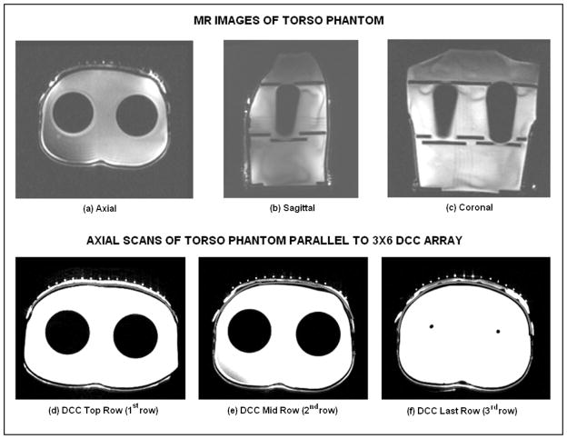
For HDR brachytherapy, patient specific pretreatment plans are generated and optimized to deliver uniform radiation dose to the target tissue. Due to the high sensitivity of dose to the source-skin distance in HDR brachytherapy, it is crucial to maintain tight control of separation between the skin and brachytherapy catheter array so that the radiation plan optimized during patient pretreatment planning is actually delivered during the treatment. Thus, it is highly desirable that the thickness of the bolus layer between the contoured tissue surface and HDR brachytherapy tubing array remains the same from the pretreatment scan until completion of brachytherapy. Maintaining a stable bolus thickness depends on maintaining a uniform water volume inside the bolus and stable inward pressure over the applicator from the airbladder, elastic wrap and Velcro attachments which secure the applicator to the contoured patient anatomy. The variability in thickness of the bolus layer between the torso and HDR brachytherapy tubing was measured using magnetic resonance (MR) images of the torso phantom. Figures 8(a)–(c) show MR slices of all three cross sectional planes of the torso phantom with the rectangular bolus and airbladder layers secured to the chest. The empty (air filled) brachytherapy tubing was filled with deionized water for visibility in the MR scans. Figures 8(d)–(f) show the axial slices of the torso phantom with the rectangular combination applicator taken parallel to the center of each row of the 3×6 DCC array. The thin gray colored contour on the outer side of the torso phantom (white color) indicates the outer surface of the torso phantom. It can be observed that the thickness of the waterbolus varies. The bolus thickness is almost uniform along the top (1st) row of the DCC array; reduces towards the center row (2nd) and increases towards the bottom (3rd) row which is closer to the return tubing of the waterbolus. The variation in bolus thickness seen in Figure 8 is mainly due to variation in the pressure applied while securing the applicator around the torso. While variations in source to skin distance will be accommodated in the brachytherapy treatment plan, it is crucial that this spatial variation in source-skin distance be maintained nearly constant from the time of pretreatment scan for dosimetry calculation through the end of treatment delivery.
Fig. 8.
MR scans of the water filled torso phantom with rectangular bolus and air bladder bags. (a) – (c) MR scans along three cross sectional planes illustrating the contoured surface of the phantom; (d) – (f) axial scans indicating the outline of the torso surface (dark gray), waterbolus (white) and brachytherapy tubing (white dots) parallel to the center of each row of the 3×6 DCC antenna array.
Effect of DCC Array on Radiation Dose
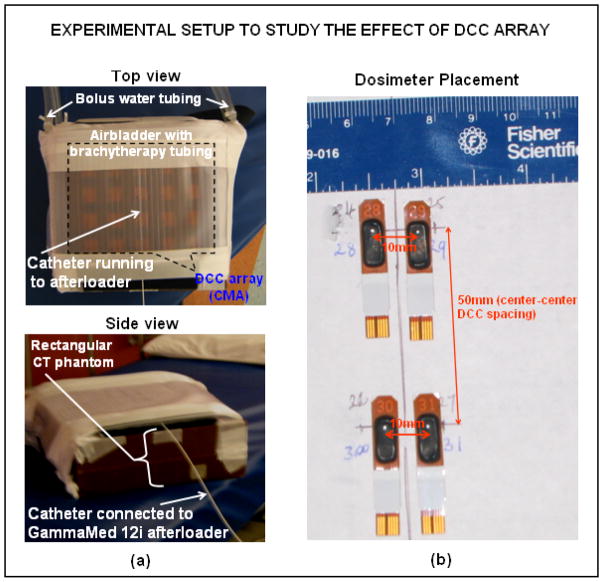
Photons from the HDR source inside the brachytherapy tubing undergo rapid attenuation as they travel through the TBSA applicator layers and also generate secondary electron emissions due to scattering from the edges of the slots in the thin (0.15 mm) copper PCB array. Commercial pretreatment planning software used for HDR brachytherapy treatments does not have provision to account for non-tissue layers. Thus, it is important to quantify the impact of the TBSA applicator on patient radiation dosimetry calculations. Simple experimental configurations using rectangular slabs of tissue equivalent CT phantom were used to quantify the radiation dose delivered by HDR. The rectangular airbladder with brachytherapy tubing and the corresponding waterbolus (~7mm thickness) was wrapped around the CT phantom as in Figure 9a. A “uniform” radiation dose of 100 cGy minimum was delivered to a 15×15cm2 region of the CT phantom through the brachytherapy tube array using a Varian GammaMed 12i afterloader (Varian Medical Systems Inc., Palo Alto, CA). Skin dose was measured at four locations on the phantom surface using OneDose™ dosimeters shown in Figure 9b (Sicel Technologies Inc., Morrisville NC) and also using an ion chamber. The dosimetric impact of the thin copper PCB heating array was assessed with and without the CMA. The PCB attenuation coefficient was measured as 3±0.001% using ion chamber and 2.95±0.03% using OneDose™ dosimeters indicating that the copper PCB does not significantly attenuate the beam.
Fig. 9.
Experimental setup used to study the effect of DCC array on radiation dose. (a) Experimental setup and (b) placement of the dosimeters on CT phantom surface.
3. CONCLUSION
This work reports progress on the development of a combination applicator for simultaneous heating using the 915 MHz DCC CMA and brachytherapy using a scanning HDR source to treat diffuse cutaneous disease typical of chestwall recurrence of breast cancer. Efforts were focused on improving thermal transfer across the bolus tissue interface by studying fluid flow dynamics inside the water coupling bolus. As the treatment surface area increases, pressure distribution in the flow channels of the waterbolus varies due to friction along the fluid path and momentum effects due to water escaping through the small openings feeding the bolus bag with open cell filter foam. Imbalance of friction and momentum effects results in nonuniform pressure distribution leading to nonuniform fluid flow through the openings in the water inlet and outlet channels. 3D fluid dynamics simulations were used to study the steady state fluid flow dynamics of earlier waterbolus designs and improve fluid flow distribution to maintain uniformly high thermal transfer across the tissue surface during hyperthermia treatment. Numerical simulations led to the design and fabrication of rectangular and L-shaped water coupling boluses with improved uniformity of fluid flow across the active bolus area. Efforts were also focused on the design and fabrication of non-square DCC slot antennas to conform tissue SAR patterns to cover irregular shaped chest wall disease that spreads around the neck and shoulders, and around under the arm. Triangular and pentagonal shaped DCC slot antennas radiating as efficiently as the square DCC element are described which allow fabrication of vest shaped CMA applicators in addition to earlier rectangular shapes possible with only square DCC elements. Besides improving the clinical performance of individual layers, significant progress was achieved in devising low cost, robust and repeatable fabrication techniques that can be used to make patient specific TBSA combination applicators that fit securely and remain fixed in place for entire thermoradiotherapy treatments which last approximately an hour. The ability to perform thermal mapping on contoured patient anatomy for feedback power control of the DCC antenna array was evaluated using the rectangular combination applicator on a torso phantom. MR scans of the torso phantom with the rectangular combination applicator in place were used to study the variability in waterbolus thickness that arise from variation in pressure applied by the airbladder, elastic attachments and Velcro closures on the contoured surface. Efforts are underway to modify the airbladder and attachments/straps to further stabilize the bolus such that the source-skin distance remains fixed over the hour long thermoradiotherapy treatment. Radiation dose measured by dosimeters on tissue equivalent CT phantoms indicated ≤3% change in dose delivered by the HDR brachytherapy source with and without the DCC antenna array in place. The performance evaluation of the improved TBSA combination applicator with preclinical testing in phantom models has provided valuable data leading to optimization of the combination applicator prior to use in the patient clinic.
Acknowledgments
This effort was supported by NIH Grants R44 CA104061 and RO1 CA70761.
References
- 1.Cancer facts and figures 2005. American Cancer Society; 2005. [Google Scholar]
- 2.Chen K, Montague E, Oswald M. Results of irradiation in the treatment of loco-regional breast cancer recurrence. Cancer. 1985;56:1269–1273. doi: 10.1002/1097-0142(19850915)56:6<1269::aid-cncr2820560608>3.0.co;2-y. [DOI] [PubMed] [Google Scholar]
- 3.Janjan N, et al. Management of locoregional recurrent breast cancer. Cancer. 1986;58:1552–1556. doi: 10.1002/1097-0142(19861001)58:7<1552::aid-cncr2820580728>3.0.co;2-w. [DOI] [PubMed] [Google Scholar]
- 4.Kapp DS. Efficacy of adjuvant hyperthermia in the treatment of superficial recurrent breast cancer: confirmation and future directions. International Journal of Radiation Oncology, Biology and Physics. 1996;35(5):1117–21. doi: 10.1016/0360-3016(96)00288-x. [DOI] [PubMed] [Google Scholar]
- 5.Kapp DS, et al. Thermoradiotherapy for residual microscopic cancer: elective or post-excisional hyperthermia and radiation therapy in the management of local-regional recurrent breast cancer. International Journal of Radiation Oncology, Biology, Physics. 1992;24(2):261–277. doi: 10.1016/0360-3016(92)90681-7. [DOI] [PubMed] [Google Scholar]
- 6.Kapp DS, Meyer JL. Breast cancer: chest wall hyperthermia-electron beam therapy. Frontiers of Radiation Therapy and Oncology. 1991;25(6):151–168. doi: 10.1159/000429586. discussion 180–2. [DOI] [PubMed] [Google Scholar]
- 7.Marcial VA. The role of radiation therapy in the multidisciplinary management of recurrent and metastatic breast cancer. Cancer. 1994;74(1):450–452. doi: 10.1002/cncr.2820741334. [DOI] [PubMed] [Google Scholar]
- 8.Donegan W, Perez-Mesa C, Watson F. A biostatistical study of local recurrent breast cancer. Surgery, Gynecology, and Obstetrics. 1966;122(3):529–540. [PubMed] [Google Scholar]
- 9.Leonard R, et al. Randomized, double-blind, placebo controlled multicenter trial of 6% Miltefosine solution, a topical chemotherapy in cutaneous metastases from breast cancer. American Journal of Clinical Oncology. 2001;19(21):4150–4159. doi: 10.1200/JCO.2001.19.21.4150. [DOI] [PubMed] [Google Scholar]
- 10.Rauschecker H, et al. Systemic therapy for treating locoregional recurrence in women with breast cancer. Cochrane Database Syst Rev. 2001;4:CD002195. doi: 10.1002/14651858.CD002195. [DOI] [PMC free article] [PubMed] [Google Scholar]
- 11.Taylor ME. Breast cancer: chest wall recurrences. Current Treatment Options Oncology. 2002;3:175–177. doi: 10.1007/s11864-002-0063-7. [DOI] [PubMed] [Google Scholar]
- 12.Zimmerman KW, Montague ED, Fletcher H. Frequency, anatomical distribution and management of local recurrences after definitive tehrapy for breast cancer. Cancer. 1966;19:67–74. doi: 10.1002/1097-0142(196601)19:1<67::aid-cncr2820190107>3.0.co;2-2. [DOI] [PubMed] [Google Scholar]
- 13.Henderson I, et al. Cancer of the breast. In: DeVita VJ, Hellman S, Rosenberg S, editors. Cancer: Principles and Practice of Oncology. 3. JB Lippincott Co; Philadelphia: 1989. pp. 1197–1249. [Google Scholar]
- 14.Bedwinek J. Radiation therapy of isolated local-regional recurrence of breast cancer: decisions regarding dose, field size, and elective irradiation of uninvolved sites. Int J Radiat Oncol Biol Phys. 1990;19(4):1093–5. doi: 10.1016/0360-3016(90)90040-q. [DOI] [PubMed] [Google Scholar]
- 15.Bedwinek JM, et al. Prognostic indications in patients with isolated local-regional recurrence of breast cancer. Cancer. 1981;47:2232–2235. doi: 10.1002/1097-0142(19810501)47:9<2232::aid-cncr2820470921>3.0.co;2-r. [DOI] [PubMed] [Google Scholar]
- 16.Stauffer PR. Evolving technology for thermal therapy of cancer. International Journal of Hyperthermia. 2005;21(8):731–744. doi: 10.1080/02656730500331868. [DOI] [PubMed] [Google Scholar]
- 17.Stauffer PR, Diederich CJ, Pouliot J. Thermal Therapy for Cancer, in Brachytherapy Physics. In: Thomadsen Rivard, Butler, editors. joint AAPM/ABS Summer School. 2. 2005. pp. 901–932. [Google Scholar]
- 18.Overgaard J. Simultaneous and sequential hyperthermia and radiation treatment of an experimental tumor and its surrounding normal tissue in vivo. International Journal of Radiation Oncology Biology Physics. 1980;6:1507–1517. doi: 10.1016/0360-3016(80)90008-5. [DOI] [PubMed] [Google Scholar]
- 19.Perez CA, et al. Clinical results of irradiation combined with local hyperthermia. Cancer. 1983;52:1597–1603. doi: 10.1002/1097-0142(19831101)52:9<1597::aid-cncr2820520910>3.0.co;2-n. [DOI] [PubMed] [Google Scholar]
- 20.Sneed PK, et al. Survival benefit of hyperthermia in a prospective randomized trial of brachytherapy boost +/− hyperthermia for glioblastoma multiforme. International Journal of Radiation Oncology, Biology and Physics. 1998;40(2):287–295. doi: 10.1016/s0360-3016(97)00731-1. [DOI] [PubMed] [Google Scholar]
- 21.Valdagni R, Amichetti M. Report of long-term follow-up in a randomized trial comparing radiation therapy and radiation therapy plus hyperthermia to metastatic lymph nodes in stage IV head and neck patients. International Journal of Radiation Oncology Biology Physics. 1994;28:163–169. doi: 10.1016/0360-3016(94)90154-6. [DOI] [PubMed] [Google Scholar]
- 22.Van der Zee J, et al. Comparison of radiotherapy alone with radiotherapy plus hyperthermia in locally advanced pelvic tumours: a prospective, randomised, multicentre trial. Lancet. 2000;355:1119–1125. doi: 10.1016/s0140-6736(00)02059-6. [DOI] [PubMed] [Google Scholar]
- 23.Vernon CC, et al. Radiotherapy with or without hyperthermia in the treatment of superficial localized breast cancer: Results from five randomized controlled trials. International Journal of Radiation Oncology, Biology and Physics. 1996;35(4):731–744. doi: 10.1016/0360-3016(96)00154-x. [DOI] [PubMed] [Google Scholar]
- 24.Jones E, et al. Randomized trial of hyperthermia and radiation for superficial tumors. Journal of Clinical Oncology. 2005;23(13):3079–3085. doi: 10.1200/JCO.2005.05.520. [DOI] [PubMed] [Google Scholar]
- 25.Perez CA, et al. Quality assurance problems in clinical hyperthermia and their impact on therapeutic outcome: a report by the Radiation Therapy Oncology Group. International Journal of Radiation Oncology, Biology and Physics. 1989;16:551–558. doi: 10.1016/0360-3016(89)90471-9. [DOI] [PubMed] [Google Scholar]
- 26.Stauffer PR, et al. Progress on Conformal Microwave Array Applicators for Heating Chestwall Disease. Thermal Treatment of Tissue: Energy Delivery and Assessment IV, Proc of SPIE. 2007 [Google Scholar]
- 27.Dewey WC, et al. In: Cell biology of hyperthermia and radiation, in Radiation Biology in Cancer Research. Meyn RE, Withers HR, editors. Raven Press; New York: 1980. pp. 589–621. [Google Scholar]
- 28.Overgaard J. The current and potential role of hyperthermia in radiotherapy. International Journal of Radiation Oncology Biology Physics. 1989;16:535–549. doi: 10.1016/0360-3016(89)90470-7. [DOI] [PubMed] [Google Scholar]
- 29.Moros EG, et al. Simultaneous delivery of electron beam therapy and ultrasound hyperthermia utilizing scanning reflectors: a feasibility study. International Journal of Radiation Oncology Biology Physics. 1995;31(4):893–904. doi: 10.1016/0360-3016(94)00469-2. [DOI] [PubMed] [Google Scholar]
- 30.Moros EG, Straube WL, Myerson RJ. Devices and techniques for the clinical application of concomitant heat and ionizing radiation by external means. Biomedical Engineering, Application, Basis, Communications. 1994;6:328–339. [Google Scholar]
- 31.Myerson RJ, et al. Simultaneous superficial hyperthermia and external radiotherapy: Report of thermal dosimetry and tolerance to treatment. Int J Hyperthermia. 1999;15:251–266. doi: 10.1080/026567399285639. [DOI] [PubMed] [Google Scholar]
- 32.Taschereau R, et al. Radiation dosimetry of a conformal heat-brachytherapy applicator. Technology in Cancer Research and Treatment. 2004;3(4):347–358. doi: 10.1177/153303460400300404. [DOI] [PubMed] [Google Scholar]
- 33.Juang T, et al. Multilayer conformal applicator for microwave heating and brachytherapy treatment of superficial tissue disease. International Journal of Hyperthermia. 2006;22(7):527–544. doi: 10.1080/02656730600931815. [DOI] [PubMed] [Google Scholar]
- 34.Rossetto F, Diederich CJ, Stauffer PR. Thermal and SAR characterization of multielement dual concentric conductor microwave applicators for hyperthermia, a theoretical investigation. Medical Physics. 2000;27(4):745–753. doi: 10.1118/1.598937. [DOI] [PubMed] [Google Scholar]
- 35.Rossetto F, Stauffer PR. Effect of complex bolus-tissue load configurations on SAR distributions from dual concentric conductor applicators. IEEE Transactions on Biomedical Engineering. 1999;46(11):1310–1319. doi: 10.1109/10.797991. [DOI] [PubMed] [Google Scholar]


