Abstract
Extracellular bone material can be characterised as a nanocomposite where, in a liquid environment, nanometre-sized hydroxyapatite crystals precipitate within as well as between long fibre-like collagen fibrils (with diameters in the 100 nm range), as evidenced from neutron diffraction and transmission electron microscopy. Accordingly, these crystals are referred to as ‘interfibrillar mineral’ and ‘extrafibrillar mineral’, respectively. From a topological viewpoint, it is probable that the mineralisations start on the surfaces of the collagen fibrils (‘mineral-encrusted fibrils’), from where the crystals grow both into the fibril and into the extrafibrillar space. Since the mineral concentration depends on the pore spaces within the fibrils and between the fibrils (there is more space between them), the majority of the crystals (but clearly not all of them) typically lie in the extrafibrillar space. There, larger crystal agglomerations or clusters, spanning tens to hundreds of nanometers, develop in the course of mineralisation, and the micromechanics community has identified the pivotal role, which this extrafibrillar mineral plays for tissue elasticity. In such extrafibrillar crystal agglomerates, single crystals are stuck together, their surfaces being covered with very thin water layers. Recently, the latter have caught our interest regarding strength properties (Fritsch et al. 2009 J Theor Biol. 260(2): 230–252) – we have identified these water layers as weak interfaces in the extrafibrillar mineral of bone. Rate-independent gliding effects of crystals along the aforementioned interfaces, once an elastic threshold is surpassed, can be related to overall elastoplastic material behaviour of the hierarchical material ‘bone’. Extending this idea, the present paper is devoted to viscous gliding along these interfaces, expressing itself, at the macroscale, in the well-known experimentally evidenced phenomenon of bone viscoelasticity. In this context, a multiscale homogenisation scheme is extended to viscoelasticity, mineral-cluster-specific creep parameters are identified from three-point bending tests on hydrated bone samples, and the model is validated by statistically and physically independent experiments on partially dried samples. We expect this model to be relevant when it comes to prediction of time-dependent phenomena, e.g. in the context of bone remodelling.
Keywords: viscoelasticity, bone, multiscale, creep, relaxation, gliding event
1. Introduction
‘Bone’ relates to the key load-carrying material in vertebrates: it is produced and resorbed by tens-of-micrometres-sized biological cells (osteocytes, osteoblasts, osteoclasts and their precursors; Buckwalter et al. 1995a, 1995b; Erlebacher et al. 1995; Filvaroff and Derynck 1998; Bonucci 2009), but, as such, does not belong to them – rather, at a scale of tens of micrometres, ‘bone’ appears as extracellular material. This material can be characterised as a nanocomposite where, in a liquid environment, nanometre-sized hydroxyapatite crystals precipitate within as well as between long, fibre-like collagen fibrils (with diameters in the 100 nm range), as evidenced from neutron diffraction (Lees et al. 1984; Bonar et al. 1985; Lees 1987) and transmission electron microscopy (Lees and Prostak 1988; Arsenault et al. 1991; Lees et al. 1994; Prostak and Lees 1996). Accordingly, these crystals are referred to as ‘intrafibrillar mineral’ and ‘extrafibrillar mineral’, respectively. The latter needs to be dissolved or rinsed off, as to see the collagen fibrils in atomic force microscopy (Lees et al. 1994; Sasaki et al. 2002; Hassenkam et al. 2004; Bozec et al. 2005; Hassenkam et al. 2005). From a topological viewpoint, it is probable that the mineralisation starts on the surfaces of the collagen fibrils (‘mineral-encrusted fibrils’), from where the crystals grow both into the fibril and into the extrafibrillar space (Höhling 1967; Landis et al. 1996; Sasaki et al. 2002; Wiesmann et al. 2005). Since the mineral concentration depends on the pore spaces within the fibrils and between the fibrils (there is more space between them), the majority of the crystals (but clearly not all of them) typically lies in the extrafibrillar space (Lees 1987; Hellmich and Ulm 2001; Sasaki et al. 2002). There, larger crystal agglomerations or clusters (Su et al. 2003), spanning tens to hundreds of nanometres, develop in the course of mineralisation, and the micromechanics community has identified the pivotal role, which this extrafibrillar mineral plays for tissue elasticity (Crolet et al. 1993; Aoubiza et al. 1996; Pidaparti et al. 1996; Hellmich and Ulm 2002a, 2002b, 2005a, 2005b; Hellmich et al. 2004a; Hellmich et al. 2004b; Fritsch and Hellmich 2007; Nikolov and Raabe 2008; Hamed et al. 2010; Martinez-Reina et al. 2010; Reisinger et al. 2010; Sansalone et al. 2010). In such extrafibrillar crystal agglomerates, single crystals are stuck together, their surfaces being covered with very thin water layers (Zahn and Hochrein 2003; deLeeuw 2004; Bhowmik et al. 2007; Astala and Stott 2008; Bhowmik et al. 2009; Corno et al. 2009). These layers exhibit a mass density, which is higher than that of standard liquid water, they are made of structured ‘ice-like’ water (Pan et al. 2007).
Recently, we have identified these water layers as weak interfaces in the extrafibrillar mineral of bone (Fritsch et al. 2009). In this line, rate-independent gliding effects of crystals along the aforementioned interfaces, once an elastic threshold is surpassed, can be related to overall elastoplastic material behaviour of the hierarchical material ‘bone’. Extending this idea, the present paper is devoted to viscous gliding along these interfaces, expressing itself, at the macroscale, in the well-known experimentally evidenced phenomenon of bone viscoelasticity. Based on both experimental and computational studies, the idea that water layers at water–mineral interfaces are the source of material creep is widely accepted in geophysics (see, e.g. Morrow et al. (2000) for a multitude of gouge minerals, Stipp et al. (2006) for quartzite or Tullis and Yund (1991) for albite rock), as well as in cement and concrete research (Kalinichev et al. 2007; Alizadeh et al. 2010). In cement pastes, the micro- and nanostructures of calcium silicate hydrates exhibit length dimensions similar to those found in the extrafibrillar polycrystals of bone. However, the precise local physicochemistry of water in very crowded biological or chemical environments with a characteristic length of nanometres seems to be still a matter of discussion: the slowdown of the orientational dynamics of the water molecules may be due to confined length scales or interface interactions (Moilanen et al. 2009).
The remainder of the paper is organised as follows: first, we extend the multistep homogenisation scheme of Fritsch et al. (Fritsch and Hellmich 2007; Fritsch et al. 2009) from elasticity to viscoelasticity (Section 2). Then we will first discuss experiments used for viscoelastic parameter identification (Section 3), followed by statistically and physically independent experiments used for model validation (Section 4). Finally, we will discuss composition-dependent creep behaviour of bone (Section 5), before concluding the paper (Section 6).
2. Multiscale homogenisation theory for bone viscoelasticity
2.1. Fundamentals of continuum micromechanics (random homogenisation theory) – separation of scales
Continuum micromechanics (Hill 1963, 1965; Suquet 1997; Zaoui 1997, 2002; Scheiner and Hellmich 2009) is based on the idea that a material is a microheterogeneous body filling a macrohomogeneous representative volume element (RVE) with characteristic length ℓ, ℓ ≫ d, where d stands for the characteristic length of the inhomogeneities within the RVE (see Figure 1), and ℓ ≪ ℒ, where ℒ is the characteristic lengths of geometry or loading of a structure built up by the material defined on the RVE. Quasi-homogeneous subdomains, the so-called material phases (Suquet 1997; Zaoui 1997, 2002), with known physical properties, e.g. volume fractions or elastic/viscoelastic properties, are reasonably chosen, as to describe the complicated microstructure within an RVE as simply as possible, but not simpler than that. The elastic/viscoelastic behaviour of these inhomogeneities within the RVE (material phases), as well as the volume fractions, their characteristic shapes and their interactions, are used to estimate the correlation between homogeneous deformations acting on the boundary of the RVE and resulting (average) stresses, in other words, to estimate the homogenised mechanical behaviour of the overall material.
Figure 1.
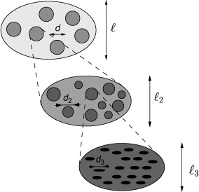
Multistep homogenisation (Fritsch and Hellmich 2007).
If a single phase has a heterogeneous microstructure itself, RVEs can be introduced within this phase in order to estimate its mechanical behaviour. These RVEs have dimensions, which fulfil ℓ2 ≤ d, and imply again smaller inhomogeneities with characteristic length d2 ≪ ℓ2, and so on (see Figure 1). Such an approach is referred to as multistep homogenisation and should, in the end, provide access to ‘universal’ phase properties at sufficiently low observation scales. For bone, we employ here a six-step homogenisation scheme (see Figure 2).
Figure 2.
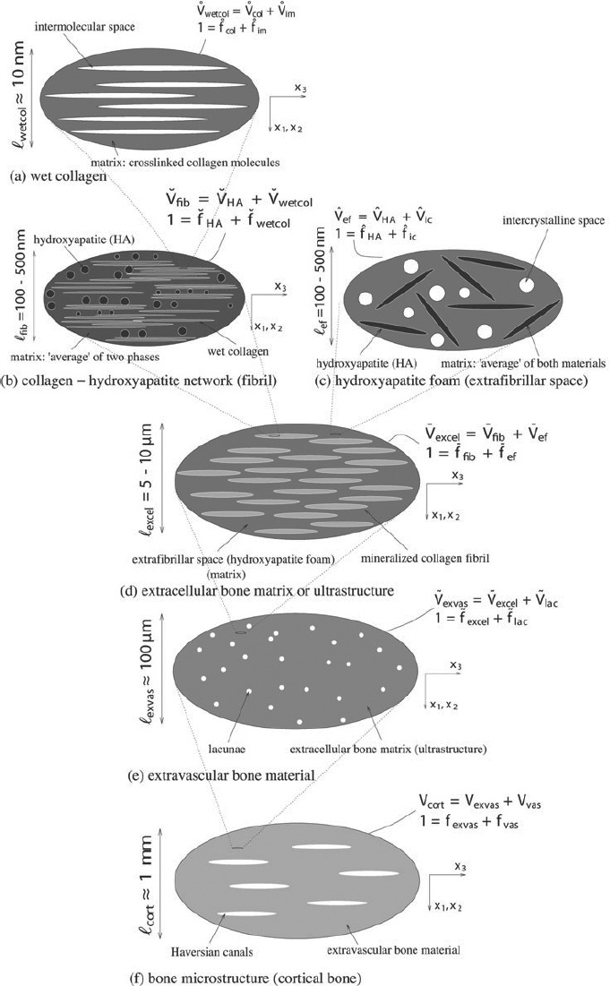
Micromechanical representation of bone material by means of a six-step homogenization scheme (Fritsch et al. 2009).
2.2. Viscoelastic homogenisation of extrafibrillar space (porous hydroxyapatite polycrystal)
2.2.1. Micromechanical representation
An RVE  ef of hydroxyapatite foam (see Figure 2(c)) has a characteristic length between 100 and 500 nm. It is built up by hydroxyapatite needles,1 being oriented in all directions (labelled by suffix ‘HA’), and spherical, water-filled pores, called intercrystalline space (labelled by suffix ‘ic’). Homogeneous (‘macroscopic’) time-dependent strains Eef(t) are imposed, in terms of displacements ξ(x, t), at the boundary of the RVEef, ∂
 ef, through
where x is the position vector inside and at the boundary of the RVEef, and t is the time variable. These macroscopic strains are identical to the spatial average of the resulting kinematically compatible (‘microscopic’) strain field ∊(x, t) across the volume of the RVE (Zaoui 2002). In our case, this reads as
 |
where r ∊ [HA, ic] and  ef are the volume of the RVEef, porosity ϕ is the volume fraction of the intercrystalline space, ∊ic refers to the spatial average of microstrains over this porosity, and ∊HA(φ, ϑ, t) are the average strains in the needle-shaped hydroxyapatite phase oriented in (φ, ϑ)-direction, see Figure 3.
Figure 3.
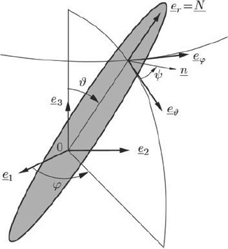
Cylindrical HA-inclusion (Fritsch et al. 2009).
Analogously, homogeneous macroscopic stresses Σef(t) are identical to the spatial average of equilibrated microstresses σ(x, t) across the RVE,
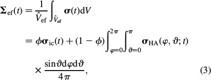 |
where σHA(φ, ϑ, t) is the average stresses in the needle-shaped hydroxyapatite phase oriented in (φ, ϑ)-direction, see Figure 3.
2.2.2. Viscoelasticity of material phases
Considering viscous interfaces of layered water2 within the extrafibrillar clusters of hydroxyapatite, as stated in the Introduction section, we assign linear viscoelastic behaviour to all needle-shaped phases in RVEef, according to
where  HA denotes the temporal derivative of the strain tensor of the hydroxyapatite needles, rHA(t – τ) is the fourth-order tensorial relaxation function, τ is the integration variable related to the time instant when ∊HA was imposed onto the needles, and ∗ represents the Stieltjes convolution operator. Thereby, rHA (t = τ) refers to instantaneous elasticity, while rHA (t > τ) refers to viscoelastic deformations. The special case of rHA = constant (∂rHA/∂t = 0) refers to pure elasticity, i.e. rHA = cHA, where cHA is the fourth-order elastic stiffness tensor of hydroxyapatite. For the subsequent developments, it is convenient to represent Equation (4) in the Laplace–Carson (LC) domain defined through ‘frequency’ variable p, with the LC transformation given as (Donolato 2002)
where f∗(p) is the LC transform of the time-dependent function f(t), and  (p) is the Laplace transform of f(t). Namely, the insertion of Equation (4) into (5) yields an algebraic equation in the LC domain, given as
Given the disordered arrangement of needle-shaped phases, it is sufficient (Fritsch et al. 2006) to assign isotropic phase properties to them, so that their relaxation tensor reads as
In Equation (7), Ivol is the volumetric part of the fourth-order unit tensor I, Ivol,ijkl = 1/3δijδkl, with Kronecker delta δij (δij = 1 if i = j, and δij = 0 if i ≠ j), while Idev is the deviatoric part of I, Idev = I – Ivol; the components of I are defined as Iijkl = 1/2(δikδjl + δilδjk). Note that the bulk modulus of hydroxyapatite is independent of p, and hence identical to the elastic bulk modulus of hydroxyapatite (see Table 1), k∗HA(p) = kHA, since gliding along interfaces does not result in any volume changes [compare also Fritsch et al. (2007) for a micromechanical development related to this statement]. For μHA, we here adopt, as a first approximation, the well-known Burgers model (TerHaar 1950; Vandamme and Ulm 2006)
Table 1.
Phase stiffness values of the elementary components of bone.
| Phase | Bulk modulus k [GPa] | Shear modulus μ [GPa] | Experimental source |
|---|---|---|---|
| Hydroxyapatite | kHA = 82.6 | μHA = 44.9 | (Katz and Ukraincik 1971) |
| Water containing | |||
| Non-collagenous | |||
| Organics or osteocytes | kH2O = 2.3 | μH2O = 0 | |
| cijkl [GPa] | cijkl [GPa] | ||
| (Molecular) collagen | ccol, 3333 = 17.9 | ccol, 1133 = 7.1 | (Cusack and Miller 1979) |
| ccol, 1111 = 11.7 | ccol, 1122 = 5.1 | ||
| ccol, 1313 = 3.3 | |||
 |
where μHA, inst is the elastic shear modulus of hydroxyapatite (see Table 1) and μKV, ηKV and ηM are the creep parameters of the Kelvin-Voigt and the Maxwell type, respectively. Identification of tissue-independent creep properties of water layer-penetrated hydroxyapatite clusters is the very focus of the present paper. However, since direct experimental determination seems to be out of reach for the moment, we will back-analyse them from creep tests on macroscopic bone samples in Section 3. Therefore, we need to proceed with the homogenisation of creep behaviour defined by Equations (7) and (8), up to the macroscopic level, as described below.
2.2.3. Homogenised viscoelastic behaviour of extrafibrillar space
Constitutive Equation (6) is formally identical to linear elasticity, so that the superposition principle is valid in the LC domain, i.e. the LC-transformed macroscopic strain E∗HA(p) is proportional to the LC-transformed microscopic strains in the needle-shaped hydroxyapatite phases,
and to the (average) microscopic strains in the intercrystalline pores
where A∗HA(φ, ϑ, p) denotes the LC-transformed fourth-order strain concentration tensor of the (φ, ϑ)-oriented hydroxyapatite phase and A∗ic(p) refers to the concentration tensor of the intercrystalline space. Equation (9) expresses the viscoelastic correspondence principle (Read 1950; Sips 1951; Laws and McLaughlin 1978; Beurthey and Zaoui 2000). Insertion of Equation (9) into the LC-transformed constitutive relation Equation (6), and averaging over all phases according to Equation (3) yields
 |
Equation (11) defines the LC-transformed homogenised relaxation tensor of the extrafibrillar space, R∗ef(p), which is the inverse of the homogenised creep tensor in the LC domain, J∗ef(p),
The concentration tensors A∗HA(φ, ϑ, p) and A∗ic(p) are determined from formally elastic matrix-inclusion problems of the Eshelby-Laws type (Eshelby 1957; Laws 1977), i.e. the average strains in each material phase are approximated by the homogeneous strains in an ellipsoidal inclusion with the phase properties, surrounded by an infinite matrix with the properties of the overall extrafibrillar polycrystal (‘self-consistent’ approach), this matrix being subjected, at infinity, to fictitious homogeneous strains E0. Accordingly, the phase strains read as
where P∗, efcyl is Hill's shape tensor of a cylindrical inclusion in the isotropic extrafibrillar matrix and P∗, efsph is the analogon for a spherical inclusion, see (Fritsch and Hellmich 2007) for details. Also, the intercrystalline space exhibits elasticity of water, cic = 3kH2OIvol. Insertion of Equations (13) and (14) into Equation (2) yields an expression for E0, and re-insertion of this expression into Equations (13) and (14), respectively, yields, according to Equations (9) and (10), the sought concentration tensors as
 |
 |
Insertion of Equations (15) and (16) into Equation (11) yields an implicit expression for the determination of R∗ef. The integrals in Equations (15) and (16) can be solved very efficiently with the help of Stroud's integration formula (Stroud 1971; Pichler et al. 2009)
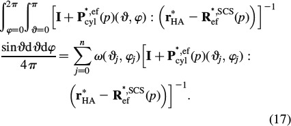 |
The scalar weight ω(ϑj, φj) and the orientations ϑj and φj are defined in Table 2.
Table 2.
Scalar weights ω(ϑj, φj) and orientations ϑj and φj for Stroud's integration (Pichler et al. 2009).
| J | 1 | 2 | 3 | 4 | 5 | 6 | 7 | 8 | 9 | 10 | 11 | 12 | 13 | 14 | 15 |
|---|---|---|---|---|---|---|---|---|---|---|---|---|---|---|---|
| sin(ϑj)cos(φj) | +r | +r | −r | −r | +t | +t | −t | −t | +s | +s | −s | −s | 1 | 0 | 0 |
| sin(ϑj)sin(φj) | +s | −s | +s | −s | +r | −r | +r | −r | +t | −t | +t | −t | 0 | 1 | 0 |
| cos(ϑj) | +t | +t | +t | +t | +s | +s | +s | +s | +r | +r | +r | +r | 0 | 0 | 1 |
| ω(ϑj, φj) | 1/15 | 1/15 | 1/15 | 1/15 | 1/15 | 1/15 | 1/15 | 1/15 | 1/15 | 1/15 | 1/15 | 1/15 | 1/15 | 1/15 | 1/15 |
r = 1/2, s = (√5 + 1)/4 and t = (√5 − 1)/4.
When summing up the tensors P∗, efcyl in Equation (17), they all have to be given in the same base frame. However, analytical expressions for Pefcyl are standardly available in a (local) base frame coinciding with the principal axis of the ellipsoid, see the Appendix. When using the [6 × 6] ‘Kelvin-Mandel’ matrix notation, given as (Nadeau and Ferrari 1998; Helnwein 2001; Cowin 2003)
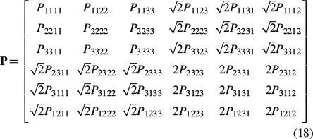 |
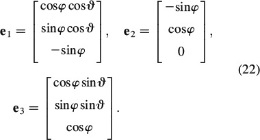
the corresponding component transformation from the local frames into one global frame can be done very efficiently through (Nadeau and Ferrari 1998)
whereby Qt(φ, ϑ) is the transpose of Q(φ, ϑ),
 |
and qij and i = 1, …, 3, j = 1, …, 3 are the elements of matrix q,
 |
2.3. Homogenisation up to the macrolevel
The viscoelastic behaviour of the remaining five homogenisation steps up to the macrolevel follows from an expression analogous to Equations (11), (15) and (16), but for a finite number of phases (Laws and McLaughlin 1978; Benveniste 1987; Zaoui 2002)
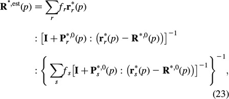 |
where r∗r is the LC-transformed relaxation tensor of phase r, fr is the volume fraction of phase r and Pr∗,0 is the LC-transformed Hill's morphology tensor of an ellipsoidal inclusion representing the characteristic shape of phase r, being embedded in a fictitious matrix with LC-transformed relaxation tensor R∗,0: choice of the latter defines the morphological nature of the material: if R∗,0 coincides with one of the phase relaxation tensors, the latter phase is a matrix, in which all other phases are embedded (Mori–Tanaka scheme (Mori and Tanaka 1973)); if R∗,0 is identical to R∗, est, then all phases are in mutual contact, as in a polycrystal (self-consistent scheme (Hershey 1954; Laws and McLaughlin 1978)). In this sense, an RVE  wetcol of wet collagen (Figure 2(a)) consists of a contiguous matrix of cross-linked molecular collagen, in which cylindrical intermolecular pores are embedded; an RVE
  fib of mineralised fibrillar material (Figure 2(b)) consists of mutually interpenetrating hydroxyapatite crystal agglomerations (of, on average, spherical shape) and cylindrical microfibrils made up of wet collagen, modelled through a self-consistent scheme; an RVE Vexcel of extracellular bone matrix (Figure 2(d)) consists of an extrafibrillar matrix with fibrillar inclusions; an RVE
  exvas of extravascular material (Figure 2(e)) consists of a matrix of extracellular matrix with embedded lacunar pores (inhabited by one osteocyte each; and being drained, i.e. exhibiting zero elastic stiffness) and an RVE Vcort of cortical bone (Figure 2(f)) consists of a matrix of extravascular material with embedded vascular pores (i.e. Haversian canals populated, among others, by osteoblasts, osteoclasts and blood vessels; being drained, i.e. exhibiting zero elastic stiffness). Explicitly, cortical bone obeys the following material behaviour
 |
In Equation (24), fexvas denotes the volume fraction and R∗exvas is the relaxation tensor of extravascular material, fvas denotes the volume fraction of the vascular pores and P∗, exvascyl denotes the Hill's tensor, accounting for cylindrical inclusions in a transversely isotropic matrix of extravascular material, for mathematical details of the used Hill's tensors, we refer to (Hellmich et al. 2004b; Fritsch and Hellmich 2007).
To be able to give the predicted relaxation functions of cortical bone from Equation (24) in a physically relevant format, we have to back-transform the LC-transformed material function R∗cort(p) into the time domain. Therefore, we employ the Gaver-Wynn-Rho algorithm (Abate and Valkó 2004; Valkó and Abate 2004), as detailed in Scheiner and Hellmich (2009). This results in a constitutive law of the format
 |
3. Creep parameter identification from three-point bending test on fully hydrated specimens
We identify the creep characteristics of water interface-penetrated hydroxyapatite clusters from three-point bending test of Iyo et al. (2004): these researchers deflected, by w = 0.39 mm, the centre of a beam on two supports, the beam's geometrical dimensions being l = 32 mm length, h = 1 mm height and b = 5 mm width. They recorded the relaxing force Fexp(t) necessary for maintaining a constant deflection of the beam. However, these force measurements are not explicitly reported in the aforementioned paper. Instead, the authors a priori assumed a fully linear viscoelastic behaviour of the beam system, and reported a corresponding (assumed) relaxation modulus RIyo(t), in the format
 |
see Table 3 for parameters E0, A1, τ1, τ2, β and γ. From this assumed relaxation modulus, the experimentally determined relaxation force Fexp(t) can be re-constructed, according to Bernoulli's beam theory
Table 3.
Parameters defining relaxation modulus assumed by Iyo et al. (2004), denoted as RIyo(t) in Equation (26).
| Direction | E0 [GPa] | A1 [-] | τ1 [s] | τ2 [×106 s] | β [-] | γ [-] |
|---|---|---|---|---|---|---|
| Longitudinal | 14.2 | 0.08 | 49 | 9.3 | 0.28 | 0.35 |
| Transverse | 11.6 | 0.11 | 50 | 6.4 | 0.26 | 0.37 |
Equation (27) relates to the statically determinate structure of a simply supported beam of length l, width b and height h, exhibiting a moment of inertia I
and with EIyo as the (assumed) maximum longitudinal strain at the beam centre, EIyo = 0.23% (Iyo et al. 2004). The experimentally determined force relaxation is depicted in Figure 4 – the initially applied force amounts to 3.4 N. We reiterate that this force would result in hypothetical elastic strain of EIyo = 0.23% at the bottom of the beam, below the load.
Figure 4.
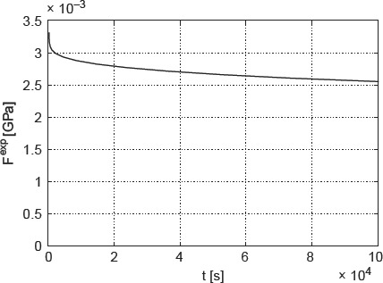
Time-dependent relaxation force Fexp(t) acting on three-point beam bending system, re-constructed from data and protocol given in Iyo et al. (2004).
However, these strains clearly exceed those related to purely elastic behaviour, amounting to about 0.045%, after which elastoplastic deformations are expected in the extrafibrillar foam (Fritsch et al. 2009). Hence, plastic events are involved in the three-point bending test. They can be quantified from a well-validated hierarchical micromechanics representation of bone (Fritsch and Hellmich 2007; Fritsch et al. 2009). When specified for bovine tibial bone (out of which Iyo et al. (2004) produced their beam samples, see Table 4 for corresponding volume fractions), this model predicts a (uniaxial) stress – (triaxial) strain behaviour as depicted in Figure 5, where Σcort, 33 refers to the uniaxial normal stress component (acting in the beam direction, see Figure 6) and Ecort, 33 denotes the strain component measuring length changes in the same direction.
Table 4.
Volume fractions for bovine tibia (Lees et al. 1979); (Fritsch and Hellmich 2007).
| ρwet | fcol | fHA | ffib |
 HA HA
|
 HA HA
|
 col col
|
fvas | flac |
|---|---|---|---|---|---|---|---|---|
| 1.99 | 0.29 | 0.46 | 0.51 | 0.65 | 0.28 | 9.41 | 0.05 | 0.02 |
Figure 5.
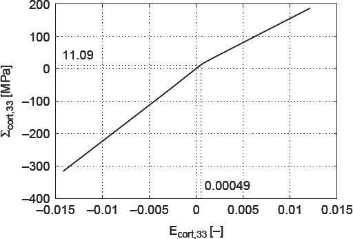
Macroscopic stress–strain diagram for bovine tibia.
Figure 6.
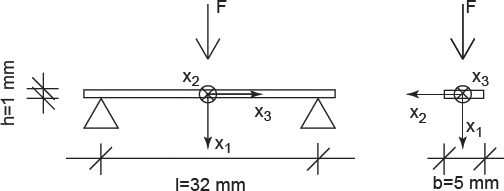
Specimen tested by Iyo et al. (2004).
In tension, the material exhibits a purely elastic behaviour below 11 MPa. Upon further increase of the load, the crystals in the extrafibrillar space start to glide along water layers, which results in an elastoplastic quasi-linear stress–strain relationship. The latter relates to a softer response than the one the material shows initially. Given such a stress–strain relationship, the initial load at the centre of the beam leads, according to Bernoulli's beam theory, to a linear total strain distribution Ecort, 33(x1), and to a bilinear stress distribution Σcort, 33(x1) = Σcort, 33(x1)e3⊗e3, with ⊗ standing for the dyadic product (Salençon 2001), across the beam cross section at the beam centre (x3 = 0), as depicted in Figure 7. The stress distribution can be transformed into a distribution of elastic strains Eelcort(x1, x3 = 0), through
Figure 7.
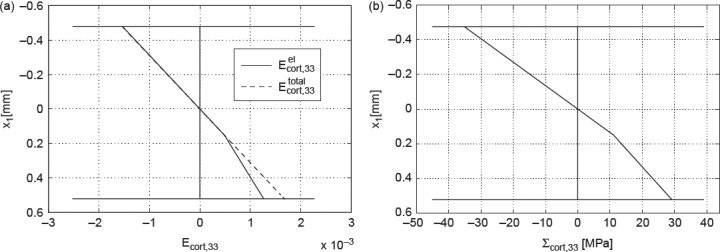
Initial stress and strain distribution over the beam height under the applied load: (a) axial normal strains (elastic and total) and (b) axial normal stresses.
with  . During the relaxation experiment, the axial normal component of the total strain, Ecort, 33, remains constant, i.e. it is time invariant [the normal strain components in one- and two-directions, though, do change (i.e. decrease) in the course of the relaxation of the beam]. Due to the stress decrease in the beam sample during relaxation, the plastic strains Eplcort remain unchanged, they are also time invariant. Conclusively, also the initially elastic axial normal strain component, Eelcort, 33, is time invariant, it plays the role of prescribed strain in a purely viscoelastic experiment. In order to preserve the mathematical format of small-strain Bernoulli beam theory, it is useful to formulate the axial stress relaxation in the LC domain
 |
where J∗cort, 3333 is the axial normal component of the LC-transformed creep tensor J∗cort(p) = R∗,−1cort(p); in Equation (30), we account for the fact that all time-invariant quantities do not depend on the frequency variable p either. Axial stresses Σ∗cort, 33 result in a bending moment around axis x2
 |
and the latter is related to the relaxing force acting in the beam centre, according to the equilibrium conditions
 |
Upon back-transformation from the LC domain to the time domain, we obtain the model-predicted force relaxation evolution Fmod(t), as a function of the (so far unknown) Burgers creep parameters of crystal clusters with wet interfaces. We can now determine the creep parameters of the Burgers model, μKV, ηKV and ηM, such that the difference between the experimental relaxation force Fexp(t) and the model-predicted relaxation force Fmod(t) is minimised. More specifically, we minimise, through a two-membered evolution strategy (Schwefel 1977; Hellmich and Ulm 2002), the standardised relative difference D, defined as
 |
The resulting Burgers parameters are listed in Table 5.
Table 5.
Burgers parameters.
| μHA, KV | 179.5262 GPa |
| ηHA, KV | 1.3430 × 10⁵ GPa s |
| ηHA, M | 1.2842 × 10⁷ GPa s |
4. Model validation by means of partially dried specimens
In order to check the relevance of the Burgers creep parameters of Table 5 (which were back-analysed from a three-point bending test on a bovine tibial sample, as described in Section 3), we use the viscoelastic multiscale model of Figure 2 (with the stiffness characteristics of Table 4 and the creep parameters in Table 5) in order to predict the viscoelastic behaviour of additional bone samples tested under conditions different from the aforementioned bending test, and we then compare the latter model predictions with corresponding experimental results. In this context, we consider the cantilever bending tests of (Sasaki et al. 1993; see Figure 8), where the beam samples are cut out of the femur of a 36-month-old cow, such that the beam axis coincides with the longitudinal material direction of the bone tissue. For such an experimental set up, Sasaki et al. (1993) examined two different cases: (i) a specimen soaked in water (with a water content of ϕ = 0.22 g water/g bone) and (ii) a partially de-hydrated specimen (with a water content of ϕ = 0.14 g water/g bone). Given the lack of more specific information and the similarity of bone tissue from bovine femur and tibia, we again employ the volume fractions given in Table 4.
Figure 8.
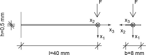
Specimen tested by (Sasaki et al. 1993).
At first, the cantilever bending tests with ϕ = 0.22 g water/g bone were examined. The experimental relaxation force and the initial distribution of the elastic strains in the cross section under the load were determined for the experimental data given in Sasaki et al. (1993) with the help of viscoelastic beam theory. The divergence between predictions and experiments is +2.52 ± 0.09% (see Figure 9).
Figure 9.
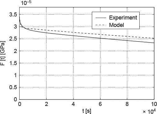
Force relaxation in water-soaked cantilever made of bovine femoral tissue: comparison of model predictions with experimental data of (Sasaki et al. 1993).
Upon drying, water is removed from the pore spaces in bone material, starting with the largest pores, the vascular pores in cortical bone (see Figure 2(f)), followed by the lacunar pores (see Figure 2(e)), before the much smaller intercrystalline pores (see Figure 2(c)) are affected. Only after excessively long drying (such as under vacuum conditions; Cusack and Miller 1979), the smallest intermolecular pores are deprived of the water bound tightly herein. The apparent mass density of water in the intercrystalline pores, per volume of extrafibrillar material, amounts to ρH2O × (1 –  HA) = 0.35 g/cm3, and the intercrystalline water concentration per volume of cortical bone amounts to 0.35 × (1 − 0.51) × (1 − 0.02) × (1 − 0.05) = 0.16 g/cm3. Consequently, a water loss from 0.22 to 0.14 g/cm3, i.e. amounting to a difference of 0.08 g/cm3, leads to emptying half of the intercrystalline pore space. Hence, only half of the extrafibrillar crystals are in contact with water, and only these are subject to viscous sliding processes. In terms of our model formulation, only half of the crystals show viscoelastic shear behaviour, the rest behaving in a purely elastic fashion. Accordingly, the partially dried sample creeps less (see Figure 10), and our model predictions are not only qualitatively correct, but also exhibit a satisfactorily small error of +1.6 ± 0.04%.
Figure 10.
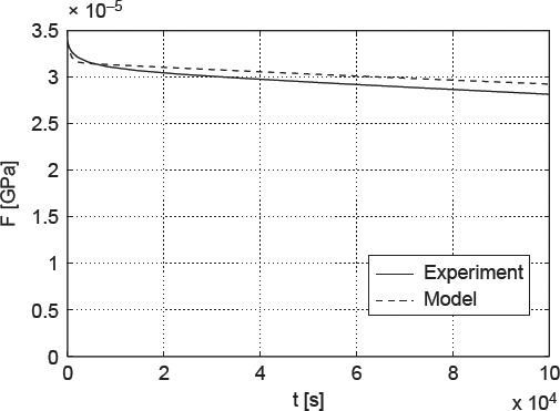
Force relaxation in partially dehydrated cantilever made of bovine femoral tissue: comparison of model predictions with experimental data of (Sasaki et al. 1993).
5. Composition-dependent creep properties – influence of extracellular mineral content and vascular porosity
Due to biodiversity, there is a great variation in bone microstructure. Because of the significant influence on viscoelastic behaviour of bone materials, especially vascular porosity and mineral content in the extracellular matrix are interesting. Considering mammals, vascular porosity in healthy cortical bone lies between 2% and 8%, and could increase up to 27% in the case of osteoporosis (Bousson et al. 2000; Fritsch et al. 2009). The chemical composition within the extravascular matrix depends only on the organ, the individual and the species, but do not vary in space and time (Boivin and Meunier 2002; Akkus et al. 2003; Roschger et al. 2003; Bossy et al. 2004; Hellmich et al. 2008; Fritsch et al. 2009). The extracellular mineral content fHA reaches from 30%, typical for deer antler, up to 70% in equine metacarpus (Fritsch et al. 2009).
Accordingly, we report studies where we vary the vascular porosity between 2% and 30%, and where the ultrastructural mineral volume is chosen between 30% and 55%; the lacunar volume fraction is kept at 2% (as in Table 4), and all other volume fractions at all remaining RVEs of Figure 2 follow from Eq. (29) to (49) of Fritsch and Hellmich (2007). In Figure 11, the effect of increasing extracellular mineral content fHA, as well as of increasing vascular porosity fvas on modulus of elasticity in longitudinal (Figure 11(a)) and transverse directions (Figure 11(b)), respectively, can be seen. Increasing fHA (with fvas kept constant) leads to an increasing Young's modulus, whereas increasing fvas (with fHA kept constant) leads to decreasing Young's modulus. These results imply that the mineral is responsible for the stiffness of bone which is consistent with the findings of Currey (2004). The variation of fHA and fvas affects the relaxation modulus 1/J3333 in the same way (see Figure 12(a), (b)).
Figure 11.
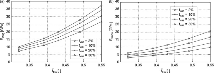
Model-predicted modulus of elasticity in (a) longitudinal direction and (b) transverse direction as function of fHA for different fvas.
Figure 12.
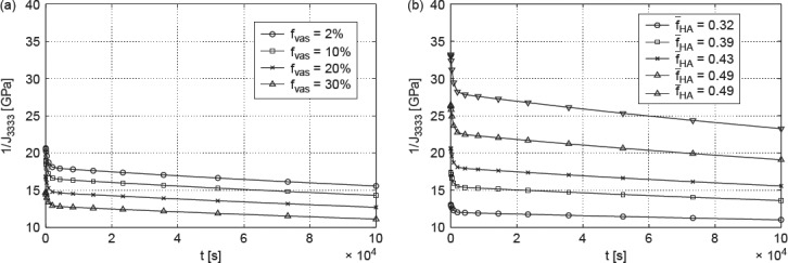
(a) Model-predicted relaxation modulus 1/J3333 for fHA = 0.43 and (b) model-predicted relaxation modulus 1/J3333 for fvas = 2%.
The plots seen in Figure 13 show the five independent components of the creep tensor J as functions of time, for different mineral content and different vascular porosities. In addition to the effects discussed before, two further phenomena can be observed: (i) an increase in fHA leads to a decrease in the creep compliances in both directions (J1111 and J3333) and (ii) this decrease is more pronounced in the transverse direction than in longitudinal direction. The first effect can be explained by the distribution of load to the hydroxyapatite needles. If the mineral content grows, e.g. if there are more needles, the load applied to one single needle reduces. Hence, the gliding of single hydroxyapatite needles on the thin water layers between them is less distinctive, and therefore the whole material creeps less. This phenomenon is direction-independent. The second effect can be explained by the fact that the minerals in the transverse direction carry much more of an overall macroscopic load than they do in longitudinal direction, where the molecular collagen contributes more. Therefore, higher mineral content expresses itself in a stiffness gain (and creep loss), which is larger in transverse and smaller in longitudinal directions. Higher contribution in load carrying may lead to earlier (and more) plastification.
Figure 13.
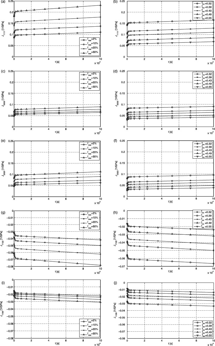
Plots for (a) J1111 for fHA = 0.43, (b) J1111 for fvas = 2%, (c) J3333 for fHA = 0.43, (d) J3333 for fvas = 2%, (e) J2323 for fHA = 0.43, (f) J2323 for fvas = 2%, (g) J1122 for fHA = 0.43, (h) J1122 for fvas = 2%, (i) J1133 for fHA = 0.43 and (j) J1133 for fvas = 2%.
6. Summary and outlook
A first approach of predicting long-term creep and relaxation functions for bone material considering a multiscale micromechanics model has been proposed in this manuscript. As to the knowledge of the authors, it was the first time that the intercrystalline water layers between hydroxyapatite needles appearing in the extrafibrillar space were regarded as responsible for the viscoelastic behaviour of cortical bone.
The Burgers model turned out to describe the creep behaviour of bone very well. In the first step, the parameters μHA, KV, ηHA, KV and ηHA, M were determined using an evolution strategy. To validate this approach, the predicted values were compared with the results of different experimental tests. The fact that the mean values of the relative error between experimental results and model estimates are less than 3% for several tests, is a clear indicator for the significance of this approach. Because of the correlation between the overall water content and the number of hydroxyapatite needles involved in gliding events, the capability of our new model to predict relaxation forces for varying water contents very well, confirms the relevance of the proposition to assign the viscoelastic properties of bone to intercrystalline water layers between the needles.
Taking a multiscale model into account allowed us to study the effects of varying extracellular mineral contents and vascular porosities on viscoelastic behaviour of bone material. As expected, enlarging the mineral content resulted in an increase of the relaxation modulus, enlarging the vascular porosity resulted in a decrease of the relaxation modulus. The creep compliance reduced as the mineral content increased, which could be explained by the distribution of the applied load on the single hydroxyapatite needles. An unequally fast decrease in the creep compliance in longitudinal and transverse directions could be attributed to the contribution of molecular collagen to load transfer. The question could be raised whether the few experimental results reported here could not have been represented by a simpler model with fewer homogenisations steps. While the answer is potentially ‘yes’, this was not the purpose of the work described herein. We are interested in the general understanding of the mechanical phenomena occurring in bone micro- and nanostructures; and in the present work, we have tackled the question whether the multiscale scheme for bone as given in Figure 2, which has been successfully validated by means of dehydration/demineralisation tests, diffraction tests, microscopic data and ultrasonic tests at different frequencies, as well as by quasi-static tests for elasticity and strength, see (Hellmich and Ulm 2003; Fritsch et al. 2007; Fritsch et al. 2009; Vuong and Hellmich 2011), would also be valid for bone creep, by just introducing tissue independent, ‘universal’ viscous properties related to sliding along interfaces of layered water. The first results shown here are affirmative.
Our work should also help to better understand, how bone works mechanically in the course of time. Especially, the ability of relaxation behaviour to reduce stress concentrations, which occur at microcracks, bone fractures or fixations of implants, for example, is of interest, in order to optimise, e.g. the treatment after bone fractures or fixation techniques. Another important area is that of mechanobiology where the time dependent, viscoelastic behaviour of bone potentially alters the characteristic times of remodelling events significantly (Lemaire et al. 2004).
Because of lack of long-term experimental data, only bovine tibia was examined in this work. Investigating the viscoelastic behaviour inherent to other bones of other species emerges as interesting task of further research. In this context, enlargement of the very scarce experimental data base should be a central issue, by expanding well-designed experimental protocols both at the macroscale (Brynk et al. 2011) and at the microscale (Han et al. 2011), to creep and relaxation tests.
Acknowledgements
The authors gratefully acknowledge financial support from the European Research Council (ERC), through project FP7-257023, MICROBONE. They further appreciate the support of Andreas Fritsch with microelastoplasticity of bone.
Appendix Fourth-order Hill tensor, Pefcyl, for cylindrical inclusions in an isotropic material
The fourth-order Hill tensor, Pefcyl, for cylindrical inclusions in an isotropic material can be obtained from
 |
where the Eshelby tensor, ScylEsh, ef, is standardly defined in a local coordinate system attached to individual solid needles (as depicted in Figure 3). The corresponding non-zero components read as follows (Eshelby 1957)
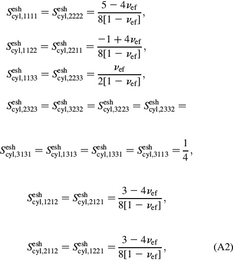 |
with the Poisson's ratio reading as
where kef and μef are the bulk and shear moduli of the extrafibrillar material.
Notes
Although sometimes referred to as ‘needles’ appearing in electron microscopy (Lees and Prostak 1988; Arsenault et al. 1991; Lees et al. 1994; Prostak and Lees 1996; Benezra Rosen et al. 2002; Rubin et al. 2003; Hong et al. 2009) there is some consensus that these ‘needles’ could be rather platelets seen ‘on-the-edge’ (Eppell et al. 2001; Su et al. 2003; Tong et al. 2003; Hassenkam et al. 2004); however, these platelets are probable to be much longer than wide (Landis et al. 1991; Moradian-Oldak et al. 1991). From a micromechanical viewpoint, the effect of needle- versus plate-shape on the overall mechanical behaviour of porous polycrystals has been shown to be a minor one (Fritsch et al. 2010).
Spreading over considerable crystal surfaces, while being negligible in terms of volume fractions.
References
- Abate J, Valkó P. Multi-precision Laplace transform inversion. Int J Numer Methods Eng. 2004;60(5):979–993. [Google Scholar]
- Akkus O, Polyakova-Akkus A, Adar F, Schaffler M. Aging of microstructural compartments in human compact bone. J Bone Miner Res. 2003;18(6):1012–1019. doi: 10.1359/jbmr.2003.18.6.1012. [DOI] [PubMed] [Google Scholar]
- Alizadeh R, Beaudoin J, Raki L. Viscoelastic nature of calcium silicate hydrate. Cem Concr Compos. 2010;32:369–376. [Google Scholar]
- Aoubiza B, Crolet J, Meunier A. On the mechanical characterization of compact bone structure using homogenization theory. J Biomech. 1996;29(6):1539–1547. [PubMed] [Google Scholar]
- Arsenault A, Frankland B, Ottensmeyer F. Vectorial sequence of mineralization in the turkey leg tendon determined by electron microscopic imaging. Calcif Tissue Int. 1991;48(1):46–55. doi: 10.1007/BF02555795. [DOI] [PubMed] [Google Scholar]
- Astala R, Stott M. First-principles study of hydroxyapatite surfaces and water adsorption. Phys Rev B. 2008;78(7/075427):1–11. [Google Scholar]
- Benezra Rosen V, Hobbs L, Spector M. The ultrastructure of anorganic bovine bone and selected synthetic hydroxyapatites used as bone graft substitute materials. Biomaterials. 2002;23:921–928. doi: 10.1016/s0142-9612(01)00204-6. [DOI] [PubMed] [Google Scholar]
- Benveniste Y. A new approach to the application of Mori-Tanakas theory in composite materials. Mech Mater. 1987;6(2):147–157. [Google Scholar]
- Beurthey S, Zaoui A. Structural morphology and relaxation spectra of viscoelastic heterogeneous materials. Eur J Mech A-Solids. 2000;19(1):1–16. [Google Scholar]
- Bhowmik R, Katti K, Katti D. Mechanics of molecular collagen is influenced by hydroxyapatite in natural bone. J Mater Sci. 2007;42(21):8795–8803. [Google Scholar]
- Bhowmik R, Katti K, Katti D. Mechanisms of load-deformation behavior of molecular collagen in hydroxyapatite-tropocollagen molecular system: steered molecular dynamics study. J Eng Mech. 2009;135(5):413–421. [Google Scholar]
- Boivin G, Meunier P. The degree of mineralization of bone tissue measured by computerized quantitative contact microradiography. Calcif Tissue Int. 2002;70(6):503–511. doi: 10.1007/s00223-001-2048-0. [DOI] [PubMed] [Google Scholar]
- Bonar L, Lees S, Mook H. Neutron diffraction studies of collagen in fully mineralized bone. J Mol Biol. 1985;181(2):265–270. doi: 10.1016/0022-2836(85)90090-7. [DOI] [PubMed] [Google Scholar]
- Bonucci E. The osteocyte: the underestimated conductor of the bone orchestra. Rend Lincei: Sci Fis Nat. 2009;20(3):237–254. [Google Scholar]
- Bossy E, Talmant M, Peyrin F, Akrout L, Cloetens P, Laugier P. An in vitro study of the ultrasonic axial transmission technique at the radius: 1 MHz velocity measurements are sensitive to both mineralization and intracortical porosity. J Bone Miner Res. 2004;19(9):1548–1556. doi: 10.1359/JBMR.040513. [DOI] [PubMed] [Google Scholar]
- Bousson V, Bergot C, Meunier A, Barbot F, Parlier-Cuau C, Laval-Jeantet AM, Laredo JD. CT of the middiaphyseal femur: cortical bone mineral density and relation to porosity. Radiology. 2000;217:179–187. doi: 10.1148/radiology.217.1.r00se11179. [DOI] [PubMed] [Google Scholar]
- Bozec L, deGroot J, Odlyhac M, Nichollsa B, Nesbitta S, Flanagand A, Horton M. Atomic force microscopy of collagen structure in bone and dentine revealed by osteoclastic resorption. Ultramicroscopy. 2005;105:79–89. doi: 10.1016/j.ultramic.2005.06.021. [DOI] [PubMed] [Google Scholar]
- Brynk T, Hellmich C, Fritsch A, Zysset P, Eberhardsteiner J. Experimental poromechanics of trabecular bone strength: role of Terzaghi's effective stress and of tissue level stress fluctuations. J Biomech. 2011;44:501–508. doi: 10.1016/j.jbiomech.2010.09.016. [DOI] [PubMed] [Google Scholar]
- Buckwalter J, Glimcher M, Cooper R, Recker R. Bone biology, part I: structure, blood supply, cells, matrix, and mineralization. J Bone Joint Surg. 1995a;77-A(8):1256–1275. [PubMed] [Google Scholar]
- Buckwalter J, Glimcher M, Cooper R, Recker R. Bone biology, part II: formation, form, modeling, remodeling, and regulation of cell functions. J Bone Joint Surg. 1995b;77-A(8):1276–1288. [PubMed] [Google Scholar]
- Corno M, Busco C, Bolis V, Tosoni S, Ugliengo P. Water adsorption on the stoichiometric (001) and (010) surfaces of hydroxyapatite: a periodic B3LYP study. Langmuir. 2009;25:2188–2198. doi: 10.1021/la803253k. [DOI] [PubMed] [Google Scholar]
- Cowin S. A recasting of anisotropic poroelasticity in matrices of tensor components. Transp Porous Media. 2003;50:35–56. [Google Scholar]
- Crolet J, Aoubiza B, Meunier A. Compact bone: numerical simulation of mechanical characteristics. J Biomech. 1993;26(6):677–687. doi: 10.1016/0021-9290(93)90031-9. [DOI] [PubMed] [Google Scholar]
- Currey J. Incompatible mechanical properties in compact bone. J Theor Biol. 2004;231:569–580. doi: 10.1016/j.jtbi.2004.07.013. [DOI] [PubMed] [Google Scholar]
- Cusack S, Miller A. Determination of the elastic constants of collagen by Brillouin light scattering. J Mol Biol. 1979;135:39–51. doi: 10.1016/0022-2836(79)90339-5. [DOI] [PubMed] [Google Scholar]
- deLeeuw N. A computer modelling study of the uptake and segregation of fluoride ions at the hydrated hydroxyapatite (0001) surface: introducing a Ca10(PO4)6(OH)2 potential model. Phys Chem Chem Phys. 2004;6:1860–1866. [Google Scholar]
- Donolato C. Analytical and numerical inversion of the Laplace-Carson transform by a differential method. Comput Phys Commun. 2002;145:298–309. [Google Scholar]
- Eppell S, Tong W, Katz J, Kuhn L, Glimcher M. Shape and size of isolated bone mineralites measured using atomic force microscopy. J Orthop Res. 2001;19:1027–1034. doi: 10.1016/S0736-0266(01)00034-1. [DOI] [PubMed] [Google Scholar]
- Erlebacher A, Filvaroff E, Gitelman S, Derynck R. Toward a molecular understanding of skeletal development. Cell. 1995;80:371–378. doi: 10.1016/0092-8674(95)90487-5. [DOI] [PubMed] [Google Scholar]
- Eshelby J. The determination of the elastic field of an ellipsoidal inclusion, and related problems. Proc R Soc London, Ser A. 1957;241:376–396. [Google Scholar]
- Filvaroff E, Derynck R. Bone remodelling: a signalling system for osteoclast regulation. Curr Biol. 1998;8:R679–R682. doi: 10.1016/s0960-9822(98)70434-8. [DOI] [PubMed] [Google Scholar]
- Fritsch A, Hellmich C. ‘Universal’ microstructural patterns in cortical and trabecular, extracellular and extravacular bone materials: micromechanics-based prediction of anisotropic elasticity. J Theor Biol. 2007;244:597–620. doi: 10.1016/j.jtbi.2006.09.013. [DOI] [PubMed] [Google Scholar]
- Fritsch A, Dormieux L, Hellmich C. Porous polycrystals built up by uniformly and axisymmetrically oriented needles: homogenization of elastic properties. C. R. Méc. 2006;334:151–157. [Google Scholar]
- Fritsch A, Dormieux L, Hellmich C, Sanahuja J. Micromechanics of crystal interfaces in polycrystalline solid phases of porous media: fundamentals and application to strength of hydroxyapatite biomaterials. J Mater Sci. 2007;42:8824–8837. [Google Scholar]
- Fritsch A, Hellmich C, Dormieux L. Ductile sliding between mineral crystals followed by rupture of collagen crosslinks: experimentally supported micromechanical explanation of bone strength. J Theor Biol. 2009;260(2):230–252. doi: 10.1016/j.jtbi.2009.05.021. [DOI] [PubMed] [Google Scholar]
- Fritsch A, Hellmich C, Dormieux L. The role of disc-type crystal shape for micromechanical predictions of elasticity and strength of hydroxyapatite biomaterials. Philos Trans R Soc A: Math, Phys Eng Sci. 2010;368:1913–1935. doi: 10.1098/rsta.2010.0005. [DOI] [PubMed] [Google Scholar]
- Hamed E, Lee Y, Jasiuk I. Multiscale modeling of elastic properties of cortical bone. Acta Mech. 2010;213:131–154. [Google Scholar]
- Han L, Wang L, Song J, Boyce M, Ortiz C. Direct quantification of the mechanical anisotropy and fracture of an individual exoskeleton layer via uniaxial compression of micropillars. Nano Lett. 2011;11:3868–3874. doi: 10.1021/nl201968u. [DOI] [PubMed] [Google Scholar]
- Hassenkam T, Fantner G, Cutroni J, Weaver J, Morse D, Hansma P. High-resolution AFM imaging of intact and fractured trabecular bone. Bone. 2004;35:4–10. doi: 10.1016/j.bone.2004.02.024. [DOI] [PubMed] [Google Scholar]
- Hassenkam T, Jorgenen H, Pedersen M, Kourakis A, Simonsen L, Lauritzen J. Atomic force microscopy on human trabecular bone from an old woman with osteoporotic fractures. Micron. 2005;36:681–687. doi: 10.1016/j.micron.2005.06.007. [DOI] [PubMed] [Google Scholar]
- Hellmich C, Ulm FJ. Hydroxyapatite is uniformly concentrated in the extracollagenous ultrastructure of mineralized tissue. 2001. In: Middleton J, Shrive N, Jones M, editors. Proceedings of the Fifth International Symposium on Computer Methods in Biomechanics and Biomedical Engineering. Rome, Italy. [DOI] [PubMed]
- Hellmich C, Ulm FJ. A micromechanical model for the ultrastructural stiffness of mineralized tissue. J Eng Mech (ASCE) 2002;128(8):898–908. [Google Scholar]
- Hellmich C, Ulm FJ. Are mineralized tissues open crystal foams reinforced by crosslinked collagen?—some energy arguments. J Biomech. 2002a;35:1199–1212. doi: 10.1016/s0021-9290(02)00080-5. [DOI] [PubMed] [Google Scholar]
- Hellmich C, Ulm FJ. A micromechanical model for the ultrastructural stiffness of mineralized tissues. J Eng Mech. (ASCE) 2002b;128(8):898–908. [Google Scholar]
- Hellmich C, Ulm FJ. Average hydroxyapatite concentration is uniform in extracollageneous ultrastructure of mineralized tissue. Biomech Model Mechanobiol. 2003;2:21–36. doi: 10.1007/s10237-002-0025-9. [DOI] [PubMed] [Google Scholar]
- Hellmich C, Ulm FJ. Drained and undrained poroelastic properties of healthy and pathological bone: a poro-micromechanical investigation. Transp Porous Media. 2005a;58:243–268. [Google Scholar]
- Hellmich C, Ulm FJ. Micro-porodynamics of bones: prediction of the ‘Frenkel-Biot’ slow compressional wave. J Eng Mech (ASCE) 2005b;131(9):918–927. [Google Scholar]
- Hellmich C, Ulm FJ, Dormieux L. Can the diverse elastic properties of trabecular and cortical bone be attributed to only a few tissue-independent phase properties and their interactions?—arguments from a multiscale approach. Biomech Model Mechanobiol. 2004a;2:219–238. doi: 10.1007/s10237-004-0040-0. [DOI] [PubMed] [Google Scholar]
- Hellmich C, Barthélémy JF, Dormieux L. Mineral-collagen interactions in elasticity of bone ultrastructure—a continuum micromechanics approach. Eur J Mech A-Solids. 2004b;23:783–810. [Google Scholar]
- Hellmich C, Kober C, Erdmann B. Micromechanics-based conversion of CT-data into anisotropic elasticity tensors, applied to FE simulations of a mandible. Ann Biomed Eng. 2008;36:108–122. doi: 10.1007/s10439-007-9393-8. [DOI] [PubMed] [Google Scholar]
- Helnwein P. Some remarks on the compressed matrix representation of symmetric second-order and fourth-order tensors. Comput Methods Appl Mech Eng. 2001;190(22–23):2753–2770. [Google Scholar]
- Hershey A. The elasticity of an isotropic aggregate of anisotropic cubic crystals. J Appl Mech (ASME) 1954;21:236–240. [Google Scholar]
- Hill R. Elastic properties of reinforced solids: some theoretical principles. J Mech Phys Solids. 1963;11:357–362. [Google Scholar]
- Hill R. Continuum micro-mechanics of elastoplastic polycrystals. J Mech Phys Solids. 1965;13(2):89–101. [Google Scholar]
- Höhling H. Collagen mineralization in bone, dentine, cementum and cartilage. Die Naturwissenschaften. 1967;56(9):466. doi: 10.1007/BF00601080. [DOI] [PubMed] [Google Scholar]
- Hong S, Hong S, Kohn D. Nanostructural analysis of trabecular bone. J Mater Sci Mater Med. 2009;20:1419–1426. doi: 10.1007/s10856-009-3708-2. [DOI] [PubMed] [Google Scholar]
- Iyo T, Maki Y, Sasaki N, Nakata M. Anisotropic viscoelastic properties of cortical bone. J Biomech. 2004;37:1433–1437. doi: 10.1016/j.jbiomech.2003.12.023. [DOI] [PubMed] [Google Scholar]
- Kalinichev A, Wang J, Kirkpatrick R. Molecular dynamics modeling of the structure, dynamics and energetics of mineral-water interfaces: application to cement materials. Cem Concr Res. 2007;37:337–347. [Google Scholar]
- Katz J, Ukraincik K. On the anisotropic elastic properties of hydroxyapatite. J Biomech. 1971;4:221–227. doi: 10.1016/0021-9290(71)90007-8. [DOI] [PubMed] [Google Scholar]
- Landis W, Moradian-Oldak J, Weiner S. Topographic imaging of mineral and collagen in the calcifying turkey tendon. Connect Tissue Res. 1991;25:181–196. doi: 10.3109/03008209109029155. [DOI] [PubMed] [Google Scholar]
- Landis W, Hodgens K, Song M, Arena J, Kiyonaga S, Marko M, Owen C, McEwen B. Mineralization of collagen may occur on fibril surfaces: evidence from conventional and high-voltage electron microscopy and three-dimensional imaging. J Struct Biol. 1996;117:24–35. doi: 10.1006/jsbi.1996.0066. [DOI] [PubMed] [Google Scholar]
- Laws N. The determination of stress and strain concentrations at an ellipsoidal inclusion in an anisotropic material. J Elast. 1977;7(1):91–97. [Google Scholar]
- Laws N, McLaughlin R. Self-consistent estimates for the viscoelastic creep compliances of composite materials. Proc R Soc, London, Ser A. 1978;359:251–273. [Google Scholar]
- Lees S. Considerations regarding the structure of the mammalian mineralized osteoid from viewpoint of the generalized packing model. Connect Tissue Res. 1987;16:281–303. doi: 10.3109/03008208709005616. [DOI] [PubMed] [Google Scholar]
- Lees S, Prostak K. The locus of mineral crystallites in bone. Connect Tissue Res. 1988;18:41–54. doi: 10.3109/03008208809019071. [DOI] [PubMed] [Google Scholar]
- Lees S, Heeley J, Cleary P. A study of some properties of a sample of bovine cortical bone using ultrasound. Calcif Tissue Int. 1979;29:107–117. doi: 10.1007/BF02408065. [DOI] [PubMed] [Google Scholar]
- Lees S, Bonar L, Mook H. A study of dense mineralized tissue by neutron diffraction. Int J Biol Macromol. 1984;6:321–326. [Google Scholar]
- Lees S, Prostak K, Ingle V, Kjoller K. The loci of mineral in turkey leg tendon as seen by atomic force microscope and electron microscopy. Calcif Tissue Int. 1994;55:180–189. doi: 10.1007/BF00425873. [DOI] [PubMed] [Google Scholar]
- Lemaire V, Tobin F, Greller L, Cho C, Suva L. Modeling of the interactions between osteoblast and osteoclast activities in bone remodeling. J Theor Biol. 2004;229(3):293–309. doi: 10.1016/j.jtbi.2004.03.023. [DOI] [PubMed] [Google Scholar]
- Martinez-Reina J, Dominguez J, Garcia-Aznar J. Effect of porosity and mineral content on the elastic constants of cortical bone: a multiscale approach. Biomech Model Mechanobiol. 2010;10(3):309–322. doi: 10.1007/s10237-010-0236-4. [DOI] [PubMed] [Google Scholar]
- Moilanen D, Fenn E, Wong D, Fayer M. Geometry and nanolength scales versus interface interactions: water dynamics in AOT lamellar structures and reverse micelles. J Am Chem Soc. 2009;131:8318–8328. doi: 10.1021/ja901950b. [DOI] [PubMed] [Google Scholar]
- Moradian-Oldak J, Weiner S, Addadi L, Landis W, Traub W. Electron imaging and diffraction study of individual crystals of bone, mineralized tendon and synthetic carbonate apatite. Connect Tissue Res. 1991;25:219–228. doi: 10.3109/03008209109029158. [DOI] [PubMed] [Google Scholar]
- Mori T, Tanaka K. Average stress in matrix and average elastic energy of materials with misfitting inclusions. Acta Metall. 1973;21(5):571–574. [Google Scholar]
- Morrow C, Moore D, Lockner D. The effect of mineral bond strength and absorbed water on fault gouge frictional strength. Geophys Res Lett. 2000;27:815–818. [Google Scholar]
- Nadeau J, Ferrari M. Invariant tensor-to-matrix mappings for evaluation of tensorial expressions. J Elast. 1998;52:43–61. [Google Scholar]
- Nikolov S, Raabe D. Hierarchical modeling of the elastic properties of bone at submicron scales: the role of extrafibrillar mineralization. Biophys J. 2008;94:4220–4232. doi: 10.1529/biophysj.107.125567. [DOI] [PMC free article] [PubMed] [Google Scholar]
- Pan H, Tao J, Wu T, Tang R. Molecular simulation of water behaviors on crystal faces of hydroxyapatite. Front Chem Chin. 2007;2(2):156–163. [Google Scholar]
- Pichler B, Hellmich C, Eberhardsteiner J. Spherical and acicular representation of hydrates in a micromechanical model for cement paste: prediction of early-age elasticity and strength. Acta Mech. 2009;203:137–162. [Google Scholar]
- Pidaparti R, Chandran A, Takano Y, Turner C. Bone mineral lies mainly outside the collagen fibrils: predictions of a composite model for osteonal bone. J Biomech. 1996;29(7):909–916. doi: 10.1016/0021-9290(95)00147-6. [DOI] [PubMed] [Google Scholar]
- Prostak K, Lees S. Visualization of crystal-matrix structure. In situ demineralization of mineralized turkey leg tendon and bone. Calcif Tissue Int. 1996;59:474–479. doi: 10.1007/BF00369213. [DOI] [PubMed] [Google Scholar]
- Read W. Stress analysis for compressible viscoelastic media. J Appl Phys. 1950;21(7):671–674. [Google Scholar]
- Reisinger A, Pahr D, Zysset P. Sensitivity analysis and parametric study of elastic properties of an unidirectional mineralized bone fibril-array using mean field methods. Biomech Model Mechanobiol. 2010;9(5):499–510. doi: 10.1007/s10237-010-0190-1. [DOI] [PubMed] [Google Scholar]
- Roschger P, Gupta H, Berzlanovich A, Ittner G, Dempster D, Fratzl P, Cosman F, Parisien M, Lindsay R, Nieves J, et al. Constant mineralization density distribution in cancellous human bone. Bone. 2003;32:316–323. doi: 10.1016/s8756-3282(02)00973-0. [DOI] [PubMed] [Google Scholar]
- Rubin M, Jasiuk I, Taylor J, Rubin J, Ganey T, Apkarian R. TEM analysis of the nanostructure of normal and osteoporotic human trabecular bone. Bone. 2003;33:270–283. doi: 10.1016/s8756-3282(03)00194-7. [DOI] [PubMed] [Google Scholar]
- Salençon J. Handbook of Continuum Mechanics. Berlin Heidelberg: Springer Verlag; 2001. [Google Scholar]
- Sansalone V, Naili S, Bousson V, Bergot C, Peyrin F, Zarka J, Laredo J, Haiar G. Determination of the heterogeneous anisotropic elastic properties of human femoral bone: from nanoscopic to organ scale. J Biomech. 2010;43:1857–1863. doi: 10.1016/j.jbiomech.2010.03.034. [DOI] [PubMed] [Google Scholar]
- Sasaki N, Nakayama Y, Yoshikawa M, Enyo A. Stress relaxation function of bone and bone collagen. J Biomech. 1993;26(12):1369–1376. doi: 10.1016/0021-9290(93)90088-v. [DOI] [PubMed] [Google Scholar]
- Sasaki N, Tagami A, Goto T, Taniguchi M, Nakata M, Hikichi K. Atomic force microscopic studies on the structure of bovine femoral cortical bone at the collagen fibril-mineral level. J Mater Sci: Mater Med. 2002;13:333–337. doi: 10.1023/a:1014079421895. [DOI] [PubMed] [Google Scholar]
- Scheiner S, Hellmich C. Continuum microviscoelasticity model for aging basic creep of early-age concrete. J Eng Mech. 2009;135(4):307–323. [Google Scholar]
- Schwefel H. Numerische optimierung von computer-modellen mittels der evolution-strategie [Numerical optimization of computer models by means of the evolution strategy] Basel, Switzerland (in German): Birkhäuser; 1977. [Google Scholar]
- Sips R. General theory of deformation of viscoelastic substances. J Polym Sci. 1951;7(2–3):191–205. [Google Scholar]
- Stipp M, Tullis J, Behrens H. Effect of water on the dislocation creep microstructure and flow stress of quartz and implications for the recrystallized grain size piezometer. J Geophys Res. 2006;111:B04201. [Google Scholar]
- Stroud A. Approximate calculation of multiple integrals. Englewood Cliffs: Prentice-Hall; 1971. [Google Scholar]
- Suquet P. Continuum micromechanics. Wien—New York: Springer; 1997. [Google Scholar]
- Su X, Sun K, Cui F, Landis W. Organization of apatite crystals in human woven bone. Bone. 2003;32:150–162. doi: 10.1016/s8756-3282(02)00945-6. [DOI] [PubMed] [Google Scholar]
- TerHaar D. A phenomenological theory of visco-elastic behaviour. Physica (Amsterdam) 1950;16(9):719–737. [Google Scholar]
- Tong W, Glimcher M, Katz J, Kuhn L, Eppell S. Size and shape of mineralities in young bovine bone measured by atomic force microscopy. Calcif Tissue Int. 2003;72:592–598. doi: 10.1007/s00223-002-1077-7. [DOI] [PubMed] [Google Scholar]
- Tullis J, Yund R. Diffusion creep in feldspar aggregates: experimental evidence. J Struct Geol. 1991;13:987–1000. [Google Scholar]
- Valkó P, Abate J. Comparison of sequence accelerators for the Gaver method of numerical Laplace transform inversion. Comput Math App. 2004;48(3–4):629–636. [Google Scholar]
- Vandamme M, Ulm FJ. Viscoelastic solutions for conical indentations. Int J Solids Struct. 2006;43(10):3142–3165. [Google Scholar]
- Vuong J, Hellmich C. Bone fibrillogenesis and mineralization: quantitative analysis and implications for tissue elasticity. J Theor Biol. 2011;287:115–130. doi: 10.1016/j.jtbi.2011.07.028. [DOI] [PubMed] [Google Scholar]
- Wiesmann H, Meyer U, Plate U, Höhling H. Aspects of collagen mineralization in hard tissue formation. Int Rev Cytol. 2005;242:121–156. doi: 10.1016/S0074-7696(04)42003-8. [DOI] [PubMed] [Google Scholar]
- Zahn D, Hochrein O. Computational study of interfaces between hydroxyapatite and water. Phys Chem Chem Phys. 2003;5:4004–4007. [Google Scholar]
- Zaoui A. In: Structural morphology and constitutive behavior of microheterogeneous materials. Suquet, editor. Wien—New York: Springer; 1997. pp. 291–347. [Google Scholar]
- Zaoui A. Continuum micromechanics: survey. J Eng Mech (ASCE) 2002;128(8):808–816. [Google Scholar]


