Abstract
Clinical TOF PET systems achieve detection efficiency using thick crystals, typically of thickness 2–3cm. The resulting dispersion in interaction depths degrades spatial resolution for increasing radial positions due to parallax error. Furthermore, interaction depth dispersion results in time pickoff dispersion and thus in degraded timing resolution, and is therefore of added concern in TOF scanners. Using fast signal digitization, we characterize the timing performance, pulse shape and light output of LaBr3:Ce, CeBr3 and LYSO. Coincidence timing resolution is shown to degrade by ~50ps/cm for scintillator pixels of constant cross section and increasing length. By controlling irradiation depth in a scintillator pixel, we show that DOI-dependence of time pickoff is a significant factor in the loss of timing performance in thick detectors. Using the correlated DOI-dependence of time pickoff and charge collection, we apply a charge-based correction to the time pickoff, obtaining improved coincidence timing resolution of <200ps for a uniform 4×4×30mm3 LaBr3 pixel. In order to obtain both DOI identification and improved timing resolution, we design a two layer LaBr3[5%Ce]/LaBr3[30%Ce] detector of total size 4×4×30mm3, exploiting the dependence of scintillator rise time on [Ce] in LaBr3:Ce. Using signal rise time to determine interaction layer, excellent interaction layer discrimination is achieved, while maintaining coincidence timing resolution of <250ps and energy resolution <7% using a R4998 PMT. Excellent layer separation and timing performance is measured with several other commercially-available TOF photodetectors, demonstrating the practicality of this design. These results indicate the feasibility of rise time discrimination as a technique for measuring event DOI while maintaining sensitivity, timing and energy performance, in a well-known detector architecture.
Index Terms: depth-of-interaction, time-of-flight, PET, lanthanum bromide, PET
I. Introduction
The incorporation of Time of Flight (TOF) in commercial PET scanners has allowed the realization of the imaging benefits of TOF image reconstruction in a clinical setting. Since the introduction of TOF PET in recent years, a number of studies have been designed to quantify the gain with TOF for specific clinical tasks, such as lesion detectability [1–4] and accuracy and precision of lesion uptake measurements [5, 6]. The wide-spread introduction of TOF PET systems has been accompanied by a tendency towards shorter scan times for clinical studies [7], consistent with the increased information extracted from each event pair.
While comparable timing performance had been achieved in earlier systems [8, 9], their low sensitivity resulted in impractically long scan times, limiting their clinical utility. The re-emergence of TOF PET was made possible by the development of scintillator materials exhibiting high light output and fast decay times, as well as higher stopping power [10, 11]. These improvements in scintillator performance have enabled the design of TOF PET prototype and commercial systems, achieving timing resolution of 375ps [12] and 550–600ps [13–15], respectively. These systems achieve high sensitivity by operating in fully-3D data acquisition mode and using 2–3cm thick detectors, combining high geometric efficiency and detection efficiencies.
The use of thick detectors leads to a larger dispersion in the Depth-of-Interaction (DOI) of the annihilation photons in the detector. For annihilation photons incident on the detector at oblique angles, DOI dispersion leads to parallax error, and subsequent event mis-positioning. This effect can be minimized, by using thinner detectors or detector rings of larger diameter than the imaging field-of-view. Alternatively, DOI can be measured and accounted for in data reconstruction. Techniques to measure DOI in pixelated detectors include modulation of scintillation properties with DOI [16] in a continuous [17] or discrete manner [18]. Other methods extract DOI information by affecting the transport or detection of the light signal, as in multi-sided crystal readout [19], depth-dependent reflector arrangement [20], offset layers of pixelated crystals [21] or phosphor coated crystals [22].
The use of thick detector elements also results in a reduced precision of photon detection time, as recently observed with LaBr3:Ce [23], CeBr3 [24] and LSO [25]. The loss in performance is partially explained by the different propagation speeds of high energy photons and scintillation photons in matter. This difference causes a systematic shift in signal detection time with DOI, which may be measured and used to correct and improve timing resolution [25]. However, commonly used DOI encoding techniques, as described earlier, employ slower scintillators or light absorbing processes, which result in poor intrinsic timing performance, diminishing the benefits of DOI correction to timing.
In order to mitigate the effect of DOI dispersion on both spatial resolution and timing resolution, we investigate methods to measure the DOI in long, thin crystals without degrading the timing resolution of the detector. To this end, we first measure the deleterious effect of increased crystal length on timing performance, and quantify the contribution of DOI dispersion to the observed loss in timing performance. Next, we demonstrate a method for using crystal surface treatment to accentuate the dependence of signal amplitude, shape and the signal detection time on DOI, and exploit these correlated dependencies to correct the signal detection time, or time pickoff and achieve superb timing performance. Then we proceed to investigate a second method for encoding DOI information in signal shape using scintillators with differing signal rise times, presenting scintillator and photodetector selection criteria that are needed for achieving scintillator discrimination. Finally, we demonstrate the feasibility of a detector based on this second method by using a dual-layer LaBr3:Ce detector with varying Ce concentrations, achieving excellent DOI discrimination while maintaining good timing performance as measured in short crystals.
II. Materials
A. Scintillators
We evaluated the performance of detectors comprising of LaBr3:Ce, CeBr3 and LYSO. Samples of LaBr3:Ce crystals doped with molar cerium concentrations of 5%, 10%, 20% and 30% were measured. The intrinsic scintillation properties of these materials are reported in table I. LYSO samples were measured with a polished surface, while LaBr3:Ce and CeBr3 samples were measured with semi-diffuse surface finish. Due to their hygroscopic nature, all measurements with LaBr3:Ce and CeBr3 crystals were taken in a low-humidity environment maintained in a glove box.
Table I.
Scintillator properties of tested scintillators. Absolute light outputs of 74,000 and 63,000 photons/MeV have been reported [26] for LaBr3[5%Ce]. Energy resolution is reported as a FWHM(%) measured with a 25% Photon Detection Efficiency PMT. Rise time and primary decay constant of LaBr3:Ce, CeBr3 and LYSO were reported in [27], [28] and [25, 29] respectively.
| LaBr3 [5%Ce] | LaBr3 [10%Ce] | LaBr3 [20%Ce] | LaBr3 [30%Ce] | CeBr3 | LYSO | |
|---|---|---|---|---|---|---|
| Rel. Light Output | 1.00 | 0.94 | 0.92 | 0.93 | 0.85 | 0.41–0.51 |
| Energy Resolution(ΔE/E) | 3.3% | 4.2% | 4.7% | 12.0% | ||
| Primary Decay const.(ns) | 15–16 | 16.5 | 17.5 | 18 | 17 | 41–43 |
| 10–50% Signal Rise(ps) | 990 | 720 | 710 | 810 |
B. Photodetectors
Six PMTs were evaluated for rise time and timing measurements. The performance characteristics of these PMTs are summarized in table II. PMTs with rise times of <2ns were used in order to accurately measure differences in scintillator rise time of similar magnitude, while high Photon Detection Efficiency (PDE) and low single photon Transit Time Spread (TTS) allow for precise time pickoff measurement [30].
Table II.
Performance characteristics of PMTs evaluated. PMTs 1–5 were manufactured by Hamamatsu Photonics; PMT 6 was manufactured by Photonis. Performance characteristics of the Hamamatsu PMTs were measured and reported by the manufacturer [31], while the XP20D0 characteristics were measured and reported independently in [32]. PMTs bias voltages were set according to manufacturer’s recommendation.
| PMT | Designation | PDE(λ=400nm) | 10%-90% Rise(ps) | TTS(ps) |
|---|---|---|---|---|
| 1 | R4998 | 18% | 700 | 160 |
| 2 | R1635 | 17% | 800 | 700 |
| 3 | R9800 | 25% | 1000 | 270 |
| 4 | R4124 | 25% | 1100 | 500 |
| 5 | R3478 | 21% | 1300 | 360 |
| 6 | XP20D0 | 25% | 1500 | 600–800 |
C. Detector Configuration
In all measured configurations, crystals were wrapped in Teflon tape and optically coupled to the photodetector using BC-630, silicon-based optical grease. For detectors comprising of two crystal layers, the two crystals were optically coupled using BC-634A, a thin silicon optical interface pad. In both single-layer and multi-layer detectors, the crystals were coupled to the photodetector along their smaller-area face, as depicted in Fig. 1.
Fig. 1.
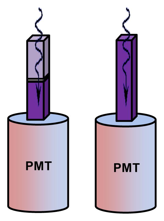
Detector configuration. (right) Single-layer detector configuration (left) multi-layer detector configuration, showing gamma entrance layer (further from PMT) and exit layer (closer to PMT). Single-layer LaBr3:Ce detector pixels were 4×4×30mm3 in size while each layer of the multilayer detector was 4×4×15mm3 in size.
D. Data Acquisition and Analysis
1) Beam Configuration
The detector was irradiated in one of two configurations: With the beam incident head on, along the long dimension of the crystal (Fig. 2a) in a regular detector configuration, or with the beam incident normal to the long dimension of the detector for measuring response at fixed DOI (Fig. 2b). For fixed DOI measurements, a narrow beam of annihilation photons was created by collimating a 22Na source using a 1mm wide slit collimator.
Fig. 2.
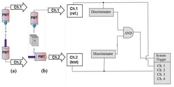
Set-up for measurement of head on (Fig. 2a) and fixed DOI (Fig 2b) irradiation of detector pixels. For fixed DOI measurements, the test detector was mounted on a height-adjustable stage, allowing control of irradiation depth. Digitizer was triggered by coincidence events as established with a LeCroy 825Z high impedance rise time-compensated discriminator and a logic circuit.
All measurements were acquired in coincidence with a reference detector, comprising of a cylindrical (L=18mm, D=14mm) LaBr3[5%Ce] crystal coupled to a Photonis XP20D0 PMT.
2) Data Acquisition
In order to maximize the flexibility of our data analysis, we digitized the output signals of our coincidence detectors and analyzed the waveforms off-line. Coincident signals were digitized for a 200ns time window using an 8-bit Agilent Acquiris DC271 cPCI digitizer, operated at a sampling rate of 2Gs/s. Coincidence was determined using NIM-based analog discriminators and coincidence units, as shown in Fig. 2. For the Hamamatsu R4998 PMT, the fastest rise time photodetector used, this sampling rate is x2 faster than the Nyquist rate [33], guaranteeing aliasing-free signal reconstruction. An analog bandwidth limit of 700MHz was applied to signals in order to limit noise components faster than the bandwidth of the PMT [34], ~500MHz. Signal oversampling allows for a reduction in the approximation error due to the finite resolution of each sample and is thus of practical benefit [35].
3) Charge Collection
Event charge was determined by summing the baseline-subtracted pulse samples over the digitization window:
| (1) |
Where Q is the integrated charge, TIntegration is the integration window, Vi is the ith digitized voltage sample, VBaseline is the average of the 80 digitized voltage samples (40ns) preceding the pulse, calculated for each pulse, and RReadout is the readout impedence of the digitizer (50Ω).
Photopeak events were well separated in all detector configurations. Fig. 3 shows a selection of 511KeV pulses, and the resulting integrated charge.
Fig. 3.
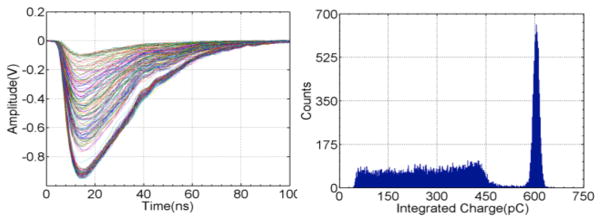
A sample of pulses digitized from the LaBr3/XP20D0 reference detector and the distribution of their calculated integrated charge. An energy gate equal to ±1 x FWHM was used to discriminate photopeak events from Compton scatter events.
4) Time Pickoff and Timing Resolution
Signal detection time, or time pickoff, was determined as the crossing time of a constant fraction (CF) of pulse amplitude. Software implementation of CF time pickoff allows for measurement of superior timing performance [36], and is insensitive to signal amplitude or shape, both of which are varied by design in these measurements. Timing threshold was optimized for to achieve best timing performance with each detector, set at 8% of Vpp and 12% of Vpp for the R4998 (fastest) and XP20D0 (slowest) PMTs, respectively. The timing performance measured using digital constant fraction discrimination was comparable to that measured with a LeCroy 825Z rise time-compensated discriminator, an analog NIM discriminator. Timing measurements were taken in coincidence with a fixed reference detector, as described in section III-A. Coincidence measurement of the reference detector with an identical detector resulted in timing resolution of 210ps±5ps. The contribution of the reference detector is subtracted in quadrature from the measured timing resolution, and the expected timing resolution for two identical detectors in coincidence is reported in all cases.
5) Pulse Shape Metrics
Signal rise time metrics were evaluated based on their ability to discriminate between photopeak energy deposition signals generated in a LaBr3[5%Ce]/R4998 detector from those generated in a LaBr3[30%Ce]/R4998 detector. Pulses from LaBr3[5%Ce] and LaBr3[30%Ce] crystals were chosen for this test since they possess the largest difference in intrinsic rise time among all LaBr3:Ce crystals measured.
We evaluated rise time metrics measured as the time difference between the crossing times of different signal thresholds on the rising edge of the pulse. These metrics are less susceptible to noise at the onset or peak of the pulse than least-squares fitting models. The time difference between a low threshold crossing of 10% of signal amplitude and a high threshold crossing, which was varied from 20% to 90% of signal amplitude, were calculated for ensembles of 10,000 photopeak pulses acquired with each detector.
III. Results
A. Effect of Crystal Length on Detector Performance
1) Timing Resolution
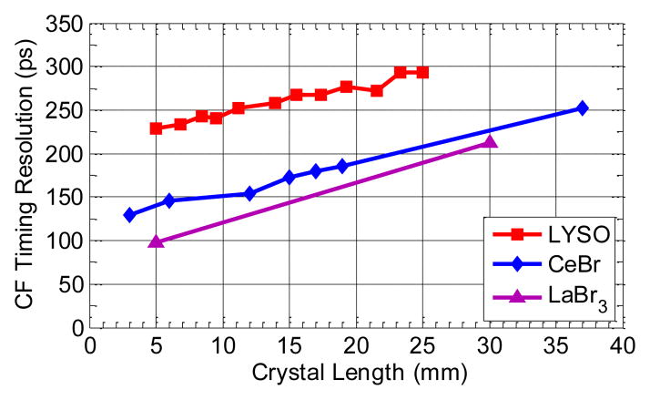
Fig. 4 shows the coincidence timing resolution measured with crystals of constant cross-section cut to different lengths, showing degradation in timing resolution with increasing crystal length for a variety of scintillators. The excellent intrinsic timing properties of LaBr3[30%Ce] and CeBr3 result in coincidence timing resolution of 98ps and 129ps for the 5mm and 3mm long crystals, respectively, measured with a Hamamatsu R4998 PMT. The reduced light output and longer decay time of LYSO allows for coincidence timing resolution of 228ps for a short pixel coupled to a R4998 PMT.
Fig. 4.
Coincidence timing resolution vs. crystal length for CeBr3, LaBr3[30%Ce] and LYSO. LaBr3[30%Ce] and LYSO samples had fixed cross section of 4×4mm2, while the CeBr3 samples were cylindrical with fixed diameter of 10mm.
For each crystal length, the timing performance of the LaBr3[30%Ce] sample is superior, followed closely by CeBr3 and then by LYSO. For all three scintillators, coincidence timing resolution degraded linearly with crystal length, exhibiting a loss of 40–50ps/cm. The magnitude of the degradation in timing performance with increased crystal length results in x2 degradation in timing performance for the 30mm long LaBr3[30%Ce] crystal as compared with the 5mm long sample of the same scintillator.
2) Charge Collection
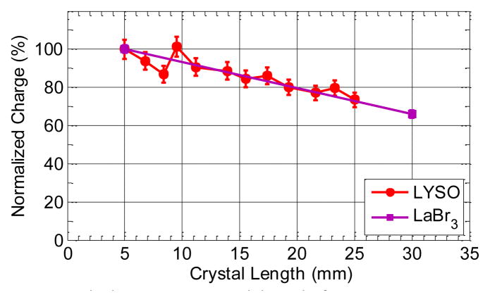
Fig. 5 shows a linear decrease in collected charge with increasing crystal length for both LaBr3 and LYSO, with a loss of 12% in charge per 1cm increase in crystal length. Based on the timing resolution measured with a 5mm long crystal and the 30% loss in light collection measured with the 30mm long pixel, we would expect timing resolution of 98ps/√0.7=117ps with the 30mm long crystal based purely on reduced light collection, as compared with a measured value of 212ps. This shows that the degradation in timing resolution measured in longer crystals is only partially explained by the correlated loss in light collection in longer crystals.
Fig. 5.
Integrated charge vs. crystal length for LaBr3[30%Ce] and LYSO samples. Charge was normalized to charge of 5mm long sample of each scintillator material, the shortest sample.
3) Pulse Shape
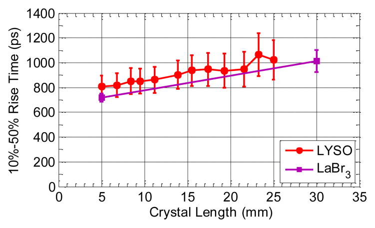
Fig. 6 shows the increase in signal rise time, measured as the 10%-50% signal rise time, with increasing crystal length, for both LYSO and LaBr3 crystals. The degradation in rise time with increasing crystal length may contribute to the degradation in timing resolution with increasing crystal length, due to the increased noise susceptibility of the time pickoff in slower rise time signals [34].
Fig. 6.
10%-50% rise time vs. crystal length for LaBr3[30%Ce] and LYSO samples.
B. Depth Dependence of Detector Response
In order to understand the factors beyond reduced light collection that lead to a degrading in timing resolution in long crystals, we experimentally controlled the 511KeV interaction depth by performing fixed DOI measurements, as seen in Fig. 2b. These measurements allow us to isolate the effect of DOI dispersion from losses in light collection and signal quality arising due to light transport in a long crystal volume.
We tested the effect of two surface treatments on depth dependence of signal response. A coarser treatment was achieved using a 1500 grit micro-mesh polishing kit, and a finer surface treatment using a 4000 grit micro-mesh polishing kit. The surface treatments were applied sequentially to the same 4×4×30mm3 LaBr3[30%Ce] crystal.
2) Time Pickoff and Timing Resolution
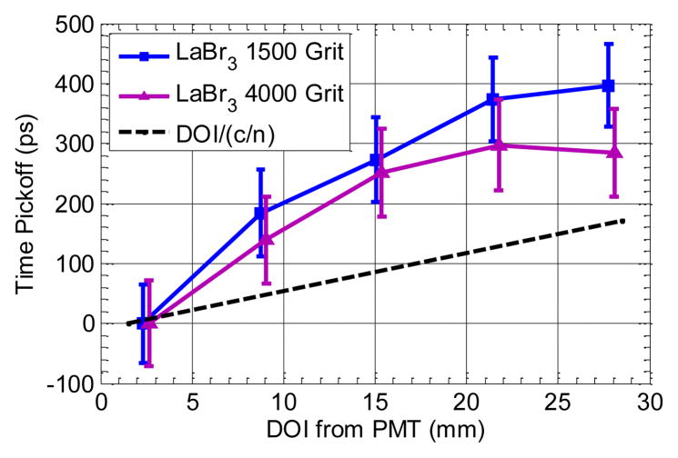
Fig. 7 shows the mean event time pickoff measured with respect to the reference detector at five fixed DOIs as a function of DOI. An increase in interaction distance from the PMT of 30mm results in a shift in mean time pickoff of 300ps for the finer surface finish, as compared to a shift of 390ps for the coarser surface finish. Note that the shift in time pickoff with interaction distance from PMT is not linear and exceeds 190ps, the delay in first photon arrival time expected for light traveling 3cm in a medium of n380nm=1.9. The change in trend of time pickoff with increasing distance from the PMT follows the trend in pulse shape with increasing distance from the PMT seen in fig. 9, offering a possible explanation for this non-linear behavior. The coincidence timing resolution of events interacting at a fixed distance from the PMT ranged from 140ps to 168ps, averaging 166ps over all depths. The altered light transport in a long pixel accounts for the degradation in coincidence timing resolution of the fixed depth 4×4×30mm3 pixel measurement (166ps) from that measured with the 4×4×5mm3 crystal (98ps).
Fig. 7.
Constant fraction time pickoff vs. interaction distance from PMT (see setup in Fig. 2b). Time pickoff was measured as the centroid of the time pickoff distribution at each depth. The error bars show ±1σ of the time pickoff distribution at each depth. Expected shift in time pickoff due to scintillation photon transit time as calculated for nLaBr=1.9, as reported by the manufacturer.
Fig. 9.
10%-50% signal rise time vs. interaction distance from PMT (see setup in Fig. 2b). Rise time was measured as the centroid of the signal rise time distribution at each depth. The error bars show ±1σ of the rise time distribution.
3) Charge Collection
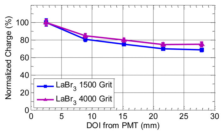
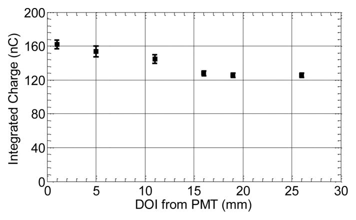
Fig. 8 shows a monotonic decrease in photopeak charge centroid as a function of DOI, indicating decreased light collection with increasing DOI from the PMT. For the coarser surface treatment, collected charge decreased by 30% for events interacting furthest from the PMT in comparison to a decrease of 25% for the finer surface treatment. Coincidence timing resolution degraded by <30ps for events interacting furthest from the PMT, despite the 25–30% decrease in light collection measured at that depth.
Fig. 8.
Averaged charge collected in response to a collimated beam of 511 keV photons interacting at fixed depths in a 4×4×30mm3 LaBr3[30%Ce] crystal. The error bars show ±1σ of the photopeak at each depth. Note the monotonic decrease in charge with increasing interaction distance from PMT.
The high light output and excellent light output uniformity of LaBr3[30%Ce] result in excellent energy resolution at each depth. The ability to resolve the change in charge with interaction depth enables good DOI discrimination among events interacting in exit half of the crystal, where the charge centroid change is most pronounced.
4) Pulse Shape
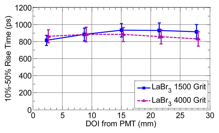
Fig. 9 shows the signal rise time, measured as the 10%-50% rise time, as a function of irradiation depth. For both surface treatments, signal rise time was slower for events interacting further from the PMT in the exit half of the crystal. A more pronounced change in rise time as a function of DOI was measured with the coarser surface treatment. The increased DOI sensitivity of rise time seen with the coarser surface treatment is consistent with the increased DOI sensitivity of the time pickoff and collected charge measured with the same surface treatment.
C. Charge-Based Time Pickoff Correction
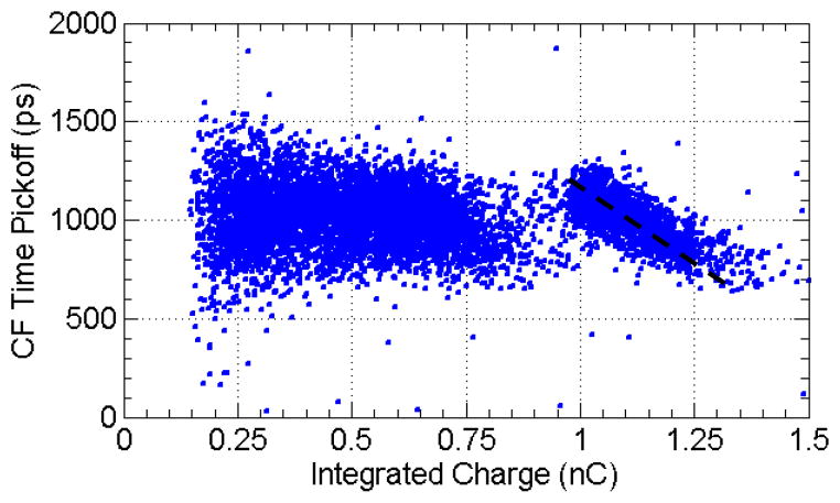
The monotonic change in charge with DOI (see Fig. 8) suggests charge may be used as a measure of DOI, and hence may be used to correct for the DOI related change in time pickoff (see Fig. 7). The correlated changes in time pickoff and charge are manifested in the response of the detector when irradiated head-on with a mono-energetic beam of 511KeV photons, as seen in Fig. 10.
Fig. 10.
Constant fraction time pickoff vs. energy for a 4×4×30mm3 LaBr3[30%Ce] crystal irradiated head-on (see setup in Fig. 2a). The correlated delay in constant fraction time pickoff with charge collection is well modeled by a straight line.
511 keV photons interacting further from the PMT result in lower integrated charge and in higher CF time pickoff as compared with photons interacting closer to the PMT. For scattered photons (integrated charge ≤ 0.8nC), depositing an unknown amount of energy, time pickoff shows no correlation with collected charge.
The correlation of time pickoff with collected charge can be exploited to improve pixel timing resolution. A least squares fit was used to model the correlation between time pickoff and collected charge for a subset of events. For a second subset of events, an event by event additive correction was applied based on the collected charge of the event. Correcting for this linear trend in time pickoff results in improved coincidence timing resolution of 192ps (see table III), showing partial recovery of the timing information lost due to DOI dispersion.
Table III.
Coincidence timing resolution for LaBr3[30%Ce] crystal.
| 4×4×5mm3 | 4×4×30mm3 Fixed DOI | 4×4×30mm3 Head On | 4×4×30mm3 Head On ChargeCorr | |
|---|---|---|---|---|
| Coinc. Tres. | 89ps | 166ps | 212ps | 192ps |
The improvement in timing resolution with charge correction, from 212ps to 192ps, demonstrates the practical ability to reduce the deleterious impact of DOI dispersion on timing resolution, however direct and well resolved DOI measurement is not possible.
D. Multi-Layer Detector Response
The systematic change in signal rise time with DOI measured in the single layer crystal (Fig. 9), from 810±60ps to 930±80ps, was mediated by the light transport process in the crystal, and offers limited DOI discrimination capability. By using scintillators exhibiting a large difference in their intrinsic rise times, a multi-layer detector may be designed, in which signal rise time is used to encode the interaction layer. Such a design allows better control of the DOI-dependence of signal rise time, thus enabling measurement of DOI which may be used to improve timing resolution by correcting the shift in time pickoff due to DOI.
1) Scintillator Selection
The effect of [Ce] on signal rise time and amplitude was evaluated using samples of LaBr3:Ce irradiated by a 511KeV source. Each sample was 4×4×30mm3 in size, and was measured with the manufacturer-supplied surface finish. The effect of [Ce] on signal charge and rise time can be seen in fig. 11.
Fig. 11.
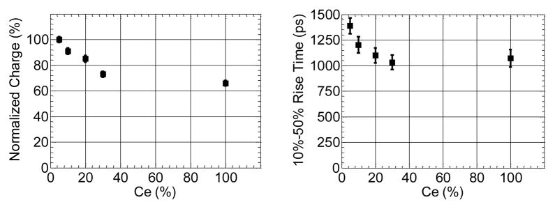
Charge and 10%-50% rise time vs. [Ce] in LaBr3:Ce samples. All samples were 4×4×30mm3 in size.
Integrated charge decreases monotonically with increasing [Ce], with 27% less charge collected with LaBr3[30%Ce] as compared to LaBr3[5%Ce] (fig. 11, left). Signal rise time decreases monotonically with increasing [Ce], decreasing by 350ps for LaBr3[30%Ce] as compared to LaBr3[5%Ce] (fig. 11, right), a significantly larger change in rise time than the 120ps difference measured at opposite edges of a single layer pixel due to light transport alone (see Fig. 9). The dependence of light output and rise time on [Ce] is consistent with performance characteristics reported by the manufacturer.
2) Rise Time Metric Optimization
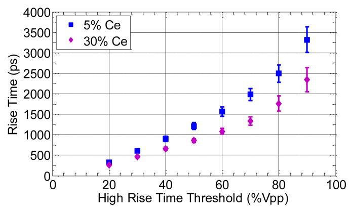
Fig. 12 shows how rise time varies with choice of upper threshold of rise time metric for 5% and 30% Ce doped LaBr3. When superimposing the measured rise time distribution of LaBr3[5%Ce] and LaBr3[30%Ce], complete separation of the two peaks is observed. Similar calculation combining LaBr3[5%Ce] and LaBr3[10%Ce], as well as LaBr3[10%Ce] and LaBr3[30%Ce] results in excellent rise time peak separation, with peak to valley separation of >7 for each of the two configurations.
Fig. 12.
Rise time peak separation. Maximal peak separation of 5.4σ is achieved for a 10%-50% threshold. Error bars represent ±1σ of measured distribution.
While the rise time of the scintillator has greatest impact at the beginning of the scintillation light pulse, poor photon statistics and limited bandwidth of the PMT result in poor separation for the 10%-20% rise time metric. Best separation between the two scintillators is achieved for the 10%-50% rise time metric, consistent with the high signal to noise expected at the peak slew rate of the pulse.
3) Layer Ordering Optimization
In order to optimally configure our detector, we measured the effect of the crystal position in a two layer detector on the measured rise time for using LaBr3[30%Ce] and LaBr3[5%Ce] crystals of size 4×4×15mm3. The rise time of each crystal was measured in three configurations: Directly coupled to the PMT, as the exit layer of the layered detector and as the entrance layer of the layered detector (see Fig. 1). Table IV shows the measurement results. For each crystal, the rise time as exit layer was comparable to the rise time measured by direct coupling. For each crystal, the entrance layer position showed 17% slower rise time than the exit layer position.
Table IV.
Average signal rise time as a function of detector configuration. Each crystal was measured directly (see Fig. 2, right), and at both exit and entrance layers of the dual-layer detector (see Fig. 2, left).
| LaBr3[30%Ce] | LaBr3[5%Ce] | |
|---|---|---|
| As exit layer | 990ps | 1280ps |
| As entrance layer | 1160ps | 1500ps |
We exploit the layer dependence of rise time in order to improve rise time separation, by positioning LaBr3[30%Ce], the intrinsically faster of the two crystals, as the exit position, in which fastest rise time was measured. LaBr3[5%Ce], the intrinsically slower of the two crystals, was positioned as the entrance layer, at which slower rise time was measured.
4) Depth Dependence of Rise Time
Fig. 13 shows the measured rise time as a function of DOI. Signal rise time changes discretely from 870±50ps for the LaBr3[30%Ce] layer to 1510±130ps for the LaBr3[5%Ce] layer. Peak separation of 7σ indicates that excellent layer discrimination may be achieved in this detector.
Fig. 13.
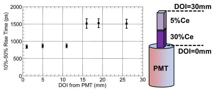
Rise time vs. interaction distance from PMT. The error bars indicate ±1σ of the measured photopeak rise time distribution.
5) Depth Dependence of Charge Collection
Collected light (see Fig. 14) showed 10% variation across the LaBr3[30%Ce] layer, and little variation across the LaBr3[5%Ce] layer. Collected charge was lower by 20% in the LaBr3[5%Ce] layer as compared to the LaBr3[30%Ce] layer. Mean energy resolution of 6.4% and 5.1% recorded for the LaBr3[30%Ce] and LaBr3[5%Ce] layers, respectively.
Fig. 14.
Integrated charge and vs. interaction distance from PMT.
6) Depth Dependence of Time Pickoff
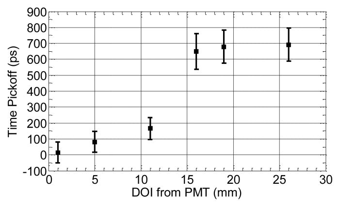
Constant-fraction time pickoff (fig. 15) shows a shift of 9±5ps/mm within each layer, which exceeds the shift of 6.3ps/mm expected due to scintillation photon propagation time alone. A similarly larger shift in time pickoff as a function of DOI was observed when irradiating a single layer 4×4×30mm3 pixel, as seen in Fig. 8. A discrete shift in time pickoff of 430ps was measured across the interface of the two layers, which is consistent with the discrete change in signal rise time and the constant fraction time pickoff method used.
Fig. 15.
Time pickoff and coincidence timing resolution vs. interaction distance from PMT.
Mean coincidence timing resolution of 155ps and 250ps was measured for the LaBr3[30%Ce] and LaBr3[5%Ce] layers, respectively.
7) DOI Correction in Multi-Layer Detector
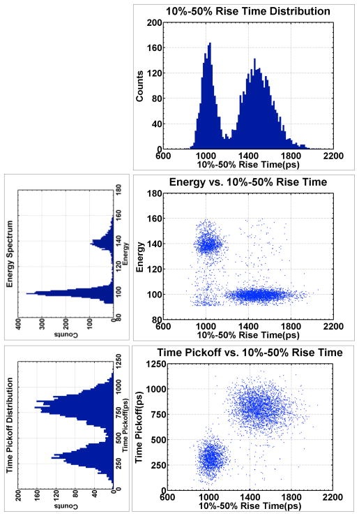
Detector response was measured for a beam of annihilation photons incident in a standard, head on orientation (Fig 2a). Integrated charge, time pickoff and rise time was measured for each coincident event. The correlations of integrated charge and time pickoff, seen in Fig. 16, with rise time are consistent with those measured at fixed DOI, verifying the layer discrimination capability of this technique.
Figure 16.
Head on detector response. (top) Rise time distribution; (center left) Charge distribution; (bottom left) Time pickoff distribution; (center right) Charge vs. rise time; (bottom right) Time pickoff vs. rise time.
Detector layer was determined based on signal rise time, and a layer-dependent time pickoff offset and charge scale factor were applied to the respective time pickoff and charge data. The calibrated data were combined and analyzed to obtain overall detector performance characteristics, summarized in table V. The 2-layer detector achieves average timing resolution of 244ps, which is comparable to the timing resolution measured in the 30mm long LaBr3[5%Ce] crystal. The head-on timing resolution of 205ps and 268ps of the exit and entrance layers, respectively, is worse than the average timing resolution of these layers measured at fixed DOIs, 155ps and 250ps.
Table V.
Performance of LaBr3[5%Ce]/LaBr3[30%Ce] detector. Response is reported for each layer individually, and for the combined detector. The performance of the uniform 4×4×30mm3 LaBr3[5%Ce] and LaBr3[30%Ce] without any DOI correction are provided for comparison.
| Entrance 4×4×15mm3 5% Ce | Exit(PMT) 4×4×15mm3 30% Ce | Combined 4×4×30mm3 5%/30% Ce | Uniform 4×4×30mm3 5% Ce | Uniform 4×4×30mm3 30% Ce | |
|---|---|---|---|---|---|
| ΔE/E (%) | 5.5% | 7.4% | 6.6% | 5.4% | 6.9% |
| Coinc. Tres. | 268ps | 205ps | 244ps | 238ps | 215ps |
8) Effect of Photodetector on Layer Discrimination
Optimal signal rise time discrimination requires accurate and precise measurement of the rise time of the scintillation pulse, which may be achieved using a fast rise time [34] TOF photodetector. To guide our PMT selection, we measured the rise time of a two layer LaBr3[5%]/LaBr3[30%] detector.
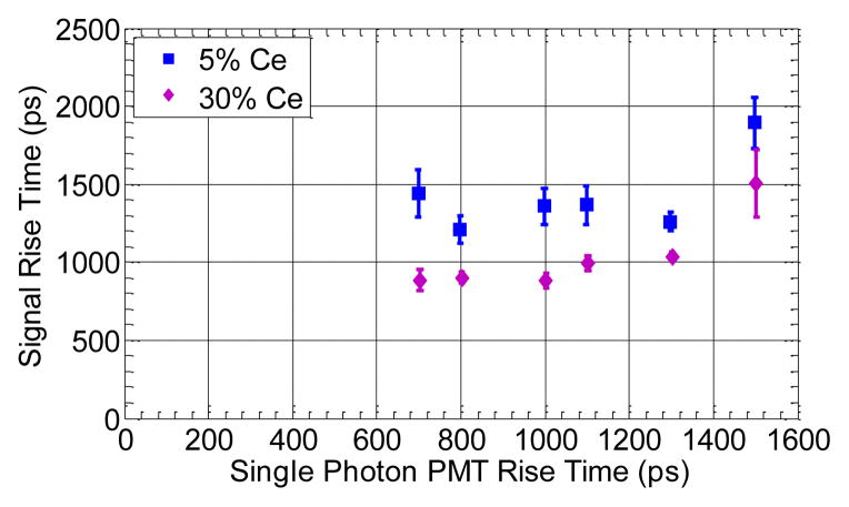
Fig. 17 shows the rise time of each layer in the detector as a function of the photodetector rise time. Rise time measurement of LaBr3[30%Ce], the faster of the two crystals, is limited by the rise time of the photodetector, as indicated by the increasing trend in measured rise time with increasing photodetector rise time. Best layer separation is achieved with the fastest PMT (R4998, 700ps); worst separation with the slowest PMT (XP20D0, 1500ps), with excellent rise time discrimination is achieved with all but the slowest photodetector.
Fig. 17.
Signal rise time vs. single photon PMT rise time for LaBr3[5%Ce]/LaBr3[30%Ce] detector for different time of flight PMTs. The error bars represent ±1σ of the measured rise time distribution for each layer/PMT combination.
IV. Discussion
Our results show that the usage of thick detectors leads to a loss of 40–50ps/cm in coincidence timing resolution, as measured with samples of LYSO, LaBr3:Ce and CeBr3. By irradiating the detector at fixed depths, we show improved timing resolution at fixed DOI, indicating that dispersion in time pickoff caused by DOI dispersion is a major source of loss in detector timing performance.
We explored two techniques for improving detector timing performance by correcting for the DOI-related shift in time pickoff. By applying a rough surface finish to a uniform 4×4×30mm3 LaBr3[30%Ce] detector, we accentuated the dependence of time pickoff, light collection and signal shape on DOI. Exploiting these correlated changes, we applied a charge-based correction to time pickoff, improving coincidence timing resolution from 212ps to 192ps, while maintaining 511keV photopeak energy discrimination. While signal rise time varied with DOI, DOI discrimination was only feasible among events interacting in the <10mm proximal to the photodetector.
In a second technique, we used a layered detector comprising of crystals of different intrinsic rise time, encoding interaction layer in signal shape. The 4×4×15mm3 LaBr3[5%Ce] and LaBr3[30%Ce] crystals demonstrated intrinsic rise time difference of <1ns, which allowed for excellent layer discrimination based on signal rise time when stacked end to end. Excellent rise time discrimination was measured with five commercially available PMT models, indicating the practical feasibility of this technique.
For each layer within the detector, average fixed DOI timing resolution (250ps for entrance layer; 155ps for exit layer) was improved as compared to the head-on timing resolution of the same layer in the detector (268ps for entrance layer; 205ps for exit layer). Improved fixed-DOI timing resolution is consistent with the behavior seen in the uniform 4×4×30mm3 LaBr3[30%Ce] detector.
By identifying interaction depth to a 4×4×15mm3 layer within the 4×4×30mm3 detector, timing resolution is may be improved. For the exit layer, we measure timing resolution of 205ps, while a comparable 4×4×30mm3 pixel exhibits timing resolution of 215ps. The mismatch in refractive index of the optical coupling layer results in significant loss in light collection from both layers, a loss which may be decreased with improved optical coupling. Nevertheless, the reduction in DOI-related timing dispersion resulted in similar overall timing resolution in the layered detector to that measured with a uniform pixel.
V. Conclusion
Using crystals of different size and by controlling irradiation depth in thick detectors, we isolated and quantified the effects leading to loss of timing performance in thick detectors. Thicker detectors demonstrate poorer light collection, slower rise time, as well as poorer timing resolution. For fixed crystal thickness, signal properties change with DOI, with fastest rise time, greatest light collection and fastest time pickoff measured closest to the photodetector. The timing resolution measured for events interacting at fixed DOIs was significantly better than the timing resolution measured without controlling DOI, and did not vary significantly with DOI. These results indicate that the systematic and uncorrected shift in signal arrival time with DOI is greatly responsible for the poorer timing performance measured in thick detectors.
The benefit of a DOI-based correction to time pickoff was tested in two detector configurations: A single layer detector, and a multi-layer detector. In the single layer detector, the correlated changes in charge and time pickoff with DOI were used to devise a charge-based correction to time pickoff, resulting in improved timing resolution. In a multi-layer detector, scintillators of different intrinsic rise time were stacked in a phoswich-like configuration, introducing a discrete DOI-dependent shift in signal rise time. Using signal rise time for DOI discrimination, excellent layer separation was achieved without compromise in average timing performance, and was shown to be feasible across an array of commercially available photodetectors.
These results demonstrate the benefit of DOI measurement to the timing performance of TOF PET detectors. Rise time discrimination offers a novel method for achieving such a measurement, holding promise for the design of a high sensitivity detector with reduced parallax error and improved timing performance.
Acknowledgments
Thanks to the research members at Saint-Gobain Crystals and Radiation Monitoring Devices for their continued support. This work was supported by NIH R01 CA113941.
Contributor Information
R.I. Wiener, Department of Physics and Astronomy at the University of Pennsylvania, Philadelphia, PA 19104 USA.
S. Surti, Department of Radiology at the University of Pennsylvania, Philadelphia, PA 19104 USA.
J.S. Karp, Department of Physics and Astronomy at the University of Pennsylvania, Philadelphia, PA 19104 USA. Department of Radiology at the University of Pennsylvania, Philadelphia, PA 19104 USA.
References
- 1.Surti S, Karp JS. Experimental evaluation of a simple lesion detection task with time-of-flight PET. Phys Med Biol. 2009;54:373–384. doi: 10.1088/0031-9155/54/2/013. [DOI] [PMC free article] [PubMed] [Google Scholar]
- 2.Kadrmas DJ, Casey ME, Conti M, Jakoby BW, Lois C, Townsend DW. Impact of Time-of-Flight on PET Tumor Detection. J Nucl Med. 2009;50:1315–1323. doi: 10.2967/jnumed.109.063016. [DOI] [PMC free article] [PubMed] [Google Scholar]
- 3.El Fakhri G, Surti S, Trott CM, Scheuermann J, Karp JS. Improvement in Lesion Detection with Whole-Body Oncologic Time-of-Flight PET. J Nucl Med. 2011;52:347–353. doi: 10.2967/jnumed.110.080382. [DOI] [PMC free article] [PubMed] [Google Scholar]
- 4.Surti S, Scheuermann J, El Fakhri G, Daube-Witherspoon ME, Lim R, Abi-Hatem N, Moussallem E, Benard F, Mankoff D, Karp JS. Impact of Time-of-Flight PET on Whole-Body Oncologic Studies: A Human Observer Lesion Detection and Localization Study. J Nucl Med. 2011;52:712–719. doi: 10.2967/jnumed.110.086678. [DOI] [PMC free article] [PubMed] [Google Scholar]
- 5.Karp JS, Surti S, Daube-Witherspoon ME, Muehllehner G. Benefit of Time-of-Flight in PET: Experimental and Clinical Results. J Nucl Med. 2008;49:462–470. doi: 10.2967/jnumed.107.044834. [DOI] [PMC free article] [PubMed] [Google Scholar]
- 6.Lois C, Jakoby BW, Long MJ, Hubner KF, Barker DW, Casey ME, Conti M, Panin VY, Kadrmas DJ, Townsend DW. An Assessment of the Impact of Incorporating Time-of-Flight Information into Clinical PET/CT Imaging. J Nucl Med. 2010;51:237–245. doi: 10.2967/jnumed.109.068098. [DOI] [PMC free article] [PubMed] [Google Scholar]
- 7.Eriksson L, Conti M, Melcher CL, Townsend DW, Eriksson M, Rothfuss H, Casey ME, Bendriem B. Towards Sub-Minute PET Examination Times. IEEE Trans Nucl Sci. 2011;58:76–81. [Google Scholar]
- 8.Allemand R, Gresset C, Vacher J. Potential advantages of a cesium fluoride scintillator for a time-of-flight positron camera. J Nucl Med. 1980;21:153–155. [PubMed] [Google Scholar]
- 9.Ishii K, Watanuki S, Orihara H, Itoh M, Matsuzawa T. Improvement of time resolution in a TOF PET system with the use of BaF2 crystals. Nucl Instr Meth. 1986;253:128–134. [Google Scholar]
- 10.van Loef EVD, Dorenbos P, van Eijk CWE, Kramer K, Gudel HU. High-energy-resolution scintillator: Ce3+ activated LaBr3. Appl Phys Lett. 2001;79:1573–1575. [Google Scholar]
- 11.Kimble T, Chou M, Chai BHT. Scintillation properties of LYSO crystals. 2002 IEEE Nucl. Sci. Symp. & Med. Imag. Conf; 2002. [Google Scholar]
- 12.Daube-Witherspoon ME, Surti S, Perkins A, Kyba CCM, Wiener R, Werner ME, Kulp R, Karp JS. The imaging performance of a LaBr 3 -based PET scanner. Phys Med Biol. 2010;55:45–64. doi: 10.1088/0031-9155/55/1/004. [DOI] [PMC free article] [PubMed] [Google Scholar]
- 13.Surti S, Kuhn A, Werner ME, Perkins AE, Kolthammer J, Karp JS. Performance of Philips Gemini TF PET/CT Scanner with Special Consideration for Its Time-of-Flight Imaging Capabilities. J Nucl Med. 2007;48:471–480. [PubMed] [Google Scholar]
- 14.Jakoby BW, Bercier Y, Conti M, Casey ME, Bendriem B, Townsend DW. Physical and clinical performance of the mCT time-of-flight PET/CT scanner. Phys Med Biol. 2011;56:2375–2389. doi: 10.1088/0031-9155/56/8/004. [DOI] [PubMed] [Google Scholar]
- 15.Bettinardi V, Presotto L, Rapisarda E, Picchio M, Gianolli L, Gilardi MC. Physical Performance of the new hybrid PET/CT Discovery-690. Med Phys. 2011;38:5394–5411. doi: 10.1118/1.3635220. [DOI] [PubMed] [Google Scholar]
- 16.Wilkinson DH. The Phoswich---A Multiple Phosphor. Rev Sci Instr. 1952;23:414–417. [Google Scholar]
- 17.Karp JSD-W, Margaret E. Depth-of-interaction determination in NaI(Tl) and BGO scintillation crystals using a temperature gradient. Nucl Instr Meth. 1987;260:509–517. [Google Scholar]
- 18.Wienhard K, Schmand M, Casey ME, Baker K, Bao J, Eriksson L, Jones WF, Knoess C, Lenox M, Lercher M, Luk P, Michel C, Reed JH, Richerzhagen N, Treffert J, Vollmar S, Young JW, Heiss W-D, Nutt R. The ECAT HRRT: Performance and first clinical application of the new high resolution research tomograph. 2002 IEEE Nucl. Sci. Symp. & Med. Imag. Conf; Norfolk, VA. 2002. [Google Scholar]
- 19.Moses WW, Derenzo SE. Design studies for a PET detector module using a PIN photodiode to measure depth of interaction. IEEE Trans Nucl Sci. 1994;41:1441–1445. [Google Scholar]
- 20.Tsuda T, Murayama H, Kitamura K, Yamaya T, Yoshida E, Omura T, Kawai H, Inadama N, Orita N. A four-Layer depth of interaction detector block for small animal PET. IEEE Trans Nucl Sci. 2004;51:2537–2542. [Google Scholar]
- 21.Robar JL, Thompson CJ, Murthy K, Clancy R, Bergman AM. Construction and calibration of detectors for high-resolution metabolic breast cancer imaging. Nucl Instr Meth. 1997;392:402–406. [Google Scholar]
- 22.Du H, Yang Y, Glodo J, Wu Y, Shah K, Cherry SR. Continuous depth-of-interaction encoding using phosphor-coated scintillators. Phys Med Biol. 2009;54:1757–1771. doi: 10.1088/0031-9155/54/6/023. [DOI] [PMC free article] [PubMed] [Google Scholar]
- 23.Kuhn A, Surti S, Shah KS, Karp JS. Investigation of LaBr3 detector timing resolution. 2005 IEEE Nucl. Sci. Symp. & Med. Imag. Conf; San Juan, PR. 2005. [Google Scholar]
- 24.Glodo J, Kuhn A, Higgins WM, van Loef EVD, Karp JS, Moses WW, Derenzo SE, Shah KS. CeBr3 for Time-of-Flight PET. 2006 IEEE Nucl. Sci. Symp & Med. Imag. Conf; San Diego, CA. 2006. [Google Scholar]
- 25.Moses WW, Derenzo SE. Prospects for time-of-flight PET using LSO scintillator. IEEE Trans Nucl Sci. 1998;46:474–478. [Google Scholar]
- 26.BrilLanCe™ 380 crystal datasheet. Available: http://www.detectors.saint-gobain.com/Brillance380.aspx.
- 27.Glodo J, Moses WW, Higgins WM, van Loef EVD, Wong P, Derenzo SE, Weber MJ, Shah KS. Effects of Ce concentration on scintillation properties of LaBr3:Ce. IEEE Trans Nucl Sci. 2005;52:1805–1808. [Google Scholar]
- 28.Shah KS, Glodo J, Higgins W, van Loef EVD, Moses WW, Derenzo SE, Weber MJ. CeBr3 scintillators for gamma-ray spectroscopy. IEEE Trans Nucl Sci. 2005;52:3157–3159. [Google Scholar]
- 29.PreLude™ 420 crystal datasheet. Available: http://www.detectors.saint-gobain.com/PreLude420.aspx.
- 30.Hyman LG. Time Resolution of Photomultiplier Systems. Rev Sci Instr. 1965;36:193–196. [Google Scholar]
- 31.Hamamatsu Photonics PMT datasheet. Available: http://sales.hamamatsu.com/en/products/electron-tube-division/detectors.
- 32.Szczesniak T, Moszynski M, Swiderski L, Nassalski A, Lavoute P, Kapusta M. Fast photomultipliers for TOF PET. 2007 IEEE Nucl. Sci. Symp. & Med. Imag. Conf; Honolulu, HI. 2007. pp. 2651–2659. [Google Scholar]
- 33.Nyquist H. Certain Topics in Telegraph Transmission Theory. Trans Amer Istitut Elec Eng. 1928;47:617–644. [Google Scholar]
- 34.Radeka V. Low-Noise Techniques in Detectors. Ann Rev Nucl Part Sci. 1988;38:217–277. [Google Scholar]
- 35.Walden RH. Analog-to-digital converter survey and analysis. IEEE J Comm. 1999;17:539–550. [Google Scholar]
- 36.Gedcke DA, McDonald WJ. A constant fraction of pulse height trigger for optimum time resolution. Nucl Instr Meth. 1967;55:377–380. [Google Scholar]


