Abstract.
Peripheral neuropathy is a common neurological problem that affects millions of people worldwide. Diagnosis and treatment of this condition are often hindered by the difficulties in making objective, noninvasive measurements of nerve fibers. Photoacoustic microscopy (PAM) has the ability to obtain high resolution, specific images of peripheral nerves without exogenous contrast. We demonstrated the first proof-of-concept imaging of peripheral nerves using PAM. As validated by both standard histology and photoacoustic spectroscopy, the origin of photoacoustic signals is myelin, the primary source of lipids in the nerves. An extracted sciatic nerve sandwiched between two layers of chicken tissue was imaged by PAM to mimic the in vivo case. Ordered fibrous structures inside the nerve, caused by the bundles of myelin-coated axons, could be observed clearly. With further technical improvements, PAM can potentially be applied to monitor and diagnose peripheral neuropathies.
Keywords: photoacoustic microscopy, peripheral nerves, myelin, label-free imaging, optical absorption contrast
1. Introduction
Peripheral neuropathy is a common neurological problem that affects 8% of people over the age of 55 and 2.4% of people overall.1 However, it is often difficult to make objective, noninvasive assessments of nerve fibers.2,3 Nerve conduction studies are currently the gold standard for diagnosis, but they cannot provide information on areas of the nerve distal to the injury and electrophysiological parameters do not always correlate well with axonal damage and regeneration.2 The ability to visualize nerves noninvasively and monitor them longitudinally could greatly improve the diagnosis and treatment of peripheral nerve diseases.
Numerous imaging modalities have been used to image peripheral nerves: ultrasound,4,5 magnetic resonance imaging (MRI),6,7 coherent anti-Stokes Raman spectroscopy (CARS),8–10 and third-harmonic generation (THG) microscopy.11,12 These imaging techniques enabled visualization of individual peripheral nerves in the body and assisted functional studies of nerves. However, neurological assessment remains challenging partly due to the technical limitations of imaging. Ultrasound images show peripheral nerves in negative contrast, which is nonspecific. THG can detect signals specifically from myelin in nerves, but it is limited by relatively low-excitation efficiency. Only nerves within a few tens of microns in depth can be sensitively detected. Although CARS affords a greater imaging depth than THG, it is still limited by the need for nonlinear excitation. Most other optical modalities rely on exogenous stains, which is a major limitation for in vivo applications. MRI is both sensitive and specific, but it cannot provide cellular resolution. Therefore, a label-free, sensitive, specific, and high-resolution imaging technique is still desired.
Optical-resolution photoacoustic microscopy (OR-PAM) is a three-dimensional (3-D) imaging modality capable of measuring endogenous optical absorption with a relative sensitivity of 100%.13–15 By utilizing the wavelengths for peak absorption, OR-PAM can image a biomolecule of interest with good sensitivity and specificity without labeling. It has been used to measure targets including hemoglobin, melanin, DNA, and cytochromes at scales down to organelles.16,17 Compared with other optical microscopy techniques, OR-PAM, which uses ultrasonic detection, has greater imaging depth as ultrasound scatters much less readily in tissue. Given the above advantages, we demonstrated OR-PAM for label-free imaging of peripheral nerves by exciting lipids at an optical wavelength of 1210 nm.
2. Methods
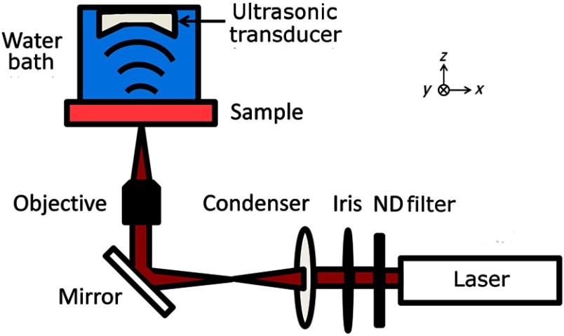
The peripheral nerves were imaged using the OR-PAM system, shown in Fig. 1, that was previously described in Ref. 17. The system employed a tunable laser, composed of a diode-pumped Q-switched Nd:YAG laser and an optical parametric oscillator system (NT242-SH, Ekspla, Vilnius, Lithuania). The light beam (5-ns pulse width, 1-KHz pulse repetition rate) was focused onto the sample by a 10X objective (LMH-10X-1064, ThorLabs, Newton, New Jersey), and the photoacoustic (PA) waves generated by the laser pulses were detected using an ultrasonic transducer (40 MHz, 80% bandwidth). The acoustic signals were digitized and recorded by a computer. The PA amplitude, proportional to the optical absorption, was calculated from each A-line signal. Images were generated by two-dimensional (2-D) raster scanning of the sample. For 3-D images, depth information was obtained from the time-of-arrival of the PA signals.
Fig. 1.
Schematic of the photoacoustic microscope (PAM). A laser pulse is attenuated by a neutral density (ND) filter, spatially filtered, and then focused by the objective onto the nerve sample. Optical absorption leads to the generation of photoacoustic waves, which are measured using an ultrasonic transducer. An image is generated by two-dimensional raster scanning of the sample.
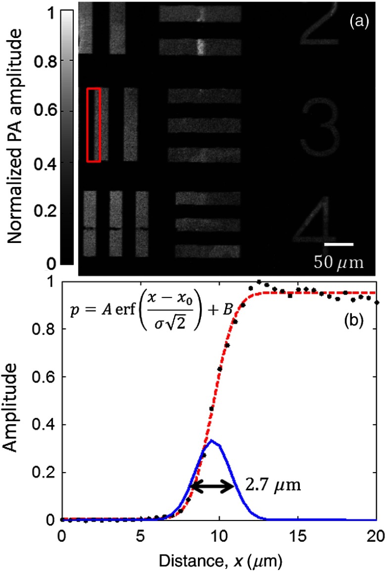
The lateral resolution of this system was evaluated by imaging a 1951 United States Air Force resolution target (Fig. 2). The edge spread function (ESF) was estimated by averaging the edge of one of the bars and was fitted to an error function ( of 0.998) based on the assumption that the beam profile was Gaussian. The point spread function (PSF) was then calculated as the derivative of the ESF. The lateral resolution, defined as the full-width half-maximum (FWHM) of the PSF, was .
Fig. 2.
(a) PAM image of a region of a 1951 United States Air Force resolution target. (b) Edge spread function (ESF) (dashed line) estimated from the region denoted by the red box. The ESF was fitted to the equation shown on the left, where is the amplitude, is the DC offset, is the horizontal axis, is the position of the edge, is the standard deviation, is the measured pressure, and erf denotes the error function. The corresponding point spread function (solid line) is also shown. Its full-width half-maximum is .
The axial resolution, determined by ultrasonic detection rather than optical focusing, was estimated by the equation , where is the speed of sound and is the bandwidth of the transducer.16 The calculated axial resolution was 41 μm. The axial resolution was also estimated by measuring the FWHM of the envelope of the photoacoustic pulse from a point target (not shown). The measured axial resolution was 48 μm.
The nerve samples consisted of sciatic nerves extracted from Swiss-Webster mice (Hsd:ND4, Harlan Laboratories, Indianapolis, Indiana). The mice were sacrificed prior to surgery. Following extraction, the nerves were fixed in 10% neutral-buffered formalin. Histological samples of the peripheral nerves were obtained by embedding the nerves in paraffin, sectioning them to 5 μm in thickness, and mounting the sections onto glass slides. Then, the slides were stained with luxol fast blue, which highlights myelin, and cresyl violet, which highlights nuclei and Nissl bodies. The stained slides were imaged using a bright-field microscope with a 20X objective (NanoZoomer 2.0-HT, Hamamatsu, Hamamatsu City, Japan).
The origins of the optical absorption of nerves were examined using PA spectroscopy. The primary absorber was hypothesized to be the lipid-rich myelin that surrounds most peripheral nerves. The absorption of myelin is strongest in the near-infrared region, where water, the most common molecule in tissue, however, is also a strong absorber.
3. Results and Discussion
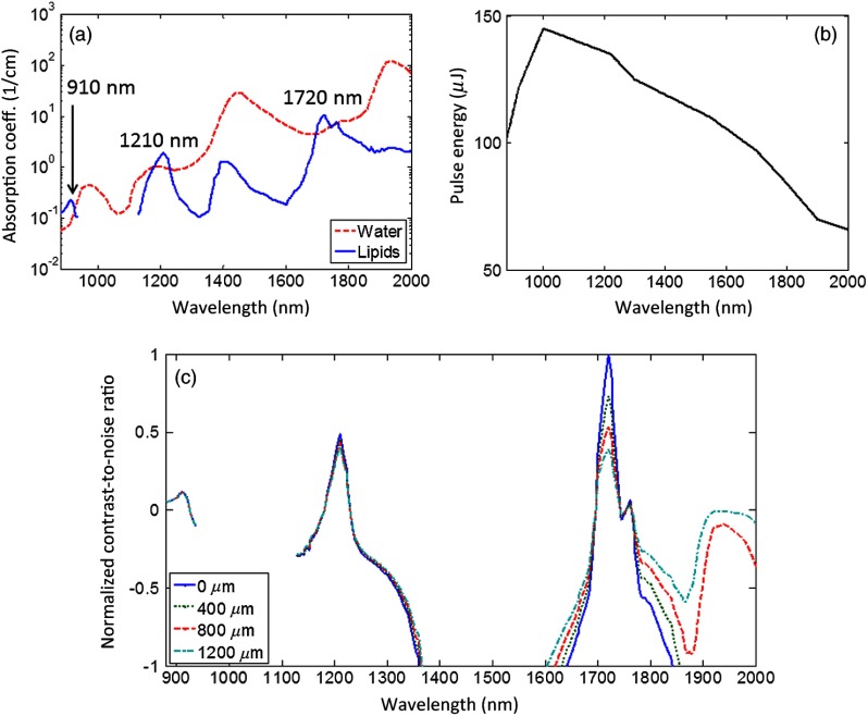
To determine the optimal wavelength for nerve imaging, the absorption coefficients of lipids and water18,19 were compared [Fig. 3(a)]. There are three regions of positive contrast for lipids, with peaks at 910, 1210, and 1720 nm. The measured PA signal is proportional to the product of the absorption coefficient and the optical fluence at the absorber. The fluence is limited by the pulse energy of the laser at that wavelength and the ability to focus light. Figure 3(b) shows the output pulse energy as a function of wavelength for the laser used in the PA microscope. The normalized contrast-to-noise ratio (CNR) versus optical wavelength were calculated for several depths [Fig. 3(c)]. Here, the noise was assumed to be primarily electronic and thus constant over the wavelength range. The contrast in relative units was calculated as the product of the fluence at that depth and the difference between the absorption coefficients of lipids and water. The fluence, in turn, was calculated as the pulse energy of the laser divided by the area of the diffraction-limited spot size. The decay in the fluence with depth was calculated based on the light absorption in a background consisting of 50% water and 50% lipids. Scattering was ignored as it changes more slowly with the wavelength. Among the three peaks, the CNR at 1720 nm is the highest at the surface, but attenuates fastest over the depth. The CNR at 1210 nm is higher than that at 1720 nm starting from approximately 1000 μm in depth. The CNR at 910 nm is the lowest at all depths. Therefore, the 1210-nm peak was selected for both the greatest CNR at depth and the finer diffraction-limited spatial resolution compared with the 1720-nm peak. In the future, measurements at this wavelength could be combined with measurements at the most negative contrast wavelengths for lipids (i.e., positive contrast for water) in order to further separate the contributions from these two absorbers.
Fig. 3.
(a) The absorption coefficients of water and lipids versus wavelength. Three peaks of positive contrast for lipids occur at 910 nm, 1210 nm, and 1720 nm. (b) The pulse energy of the laser measured at each wavelength. (c) The normalized contrast-to-noise ratio as a function of wavelength estimated for several depths: 0, 400, 800, and 1200 μm.
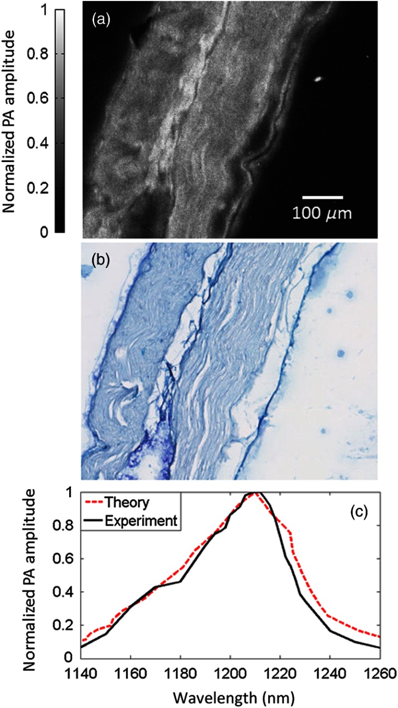
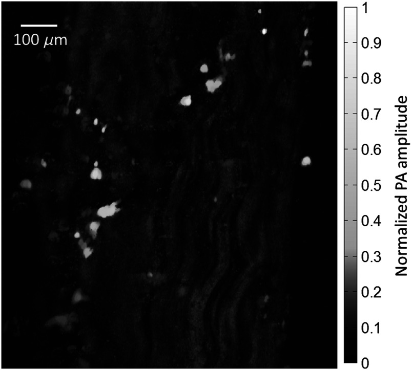
To validate that the PA image contrast is specific to myelin, a PA image was obtained of a sectioned nerve sample. The image was formed by taking the maximum amplitude projection (MAP) for each A-line signal [Fig. 4(a)]. Each pixel was then normalized by the laser pulse energy. After the PA image was acquired, the nerve section was stained with luxol fast blue, a myelin-sensitive stain, and cresyl violet, a nuclei and Nissl body-sensitive stain. This stained section was then imaged using a bright-field microscope [Fig. 4(b)]. The areas in blue denote myelin. These two images share many features. To quantify the similarity, the two images were scaled, smoothed, and coregistered, and then the correlation coefficient20 between them was calculated to be 0.75. These results indicate that PAM can be used to visualize myelin.
Fig. 4.
(a) Photoacoustic (PA) image of a sectioned, unstained sciatic nerve. (b) Bright-field optical image of a sectioned nerve stained with luxol fast blue, targeting myelin, and cresyl violet, targeting nuclei and Nissl bodies. (c) The PA spectrum of a whole nerve matches the absorption spectrum of lipids.
The source of contrast was also confirmed by examining the PA spectrum of an excised nerve from 1140 to 1260 nm. This spectrum was compared against the absorption spectrum of lipids [Fig. 4(c)]. The two spectra are in good agreement ( of 0.938), supporting the hypothesis that myelin, the primary source of lipids in the nerves, is responsible for the PA signal.
An unsectioned, “whole” nerve was also imaged ex vivo using the PA microscope. A MAP image of the nerve, again normalized by the laser pulse energy, is shown in Fig. 5. The wavy fibrous structure in the image is believed to be caused by the bundles of myelin-coated axons that form the nerve fascicles. The bright round structures may be surrounding fat cells.
Fig. 5.
The image originally contained many bright, noise-like spots, which were selectively and repetitively filtered in order to enhance the inner structure of the nerve. The source of the bright spots seen in the unsectioned nerve was uncertain, but they were not observed in the sectioned nerve samples, perhaps due to the tissue processing for histological staining.
A 3-D image of the nerve was also generated by taking the Hilbert transformation of each A-line. A similar filtering process was also applied. Video 1 steps through the image stack along the depth direction. The depth is measured from the surface of the nerve closest to the light source.
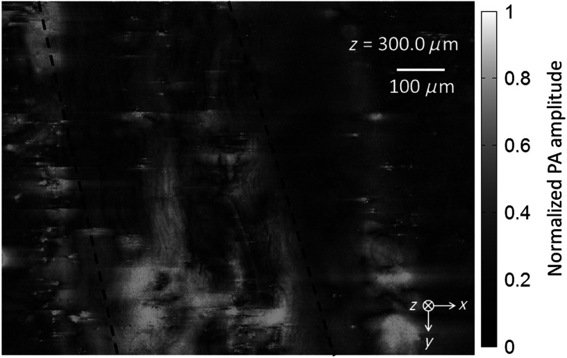
To better mimic the in vivo case, the unsectioned nerve sample was placed between two layers of chicken tissue. These layers are used to simulate the situation where the nerve is located some distance beneath the surface of the skin. The layer of chicken tissue between the optical objective and the sample was approximately 250-μm thick, and the layer between the sample and the ultrasonic transducer was approximately 400-μm thick. A 3-D image was generated as before. Video 2 shows the frames from this image along the depth direction.
Figure 6 shows one frame from this video. Even at depth, the wavy structure of the nerve is still visible. Unfortunately, both the water and lipids in the chicken tissue contributed significantly to the background. Although the background reduced the contrast of the image, the nerve can still be distinguished by its ordered structure.
Fig. 6.
4. Conclusions
The first proof-of-concept measurements of peripheral nerves using PAM were demonstrated. A good agreement was shown between the PA images and the histology images as well as between the PA spectrum and the known absorption spectrum of lipids. The nerves were also imaged beneath a layer of chicken tissue to simulate imaging the nerve at depth. Additional work is needed to improve the signal-to-noise ratio beneath the surface and to allow in vivo, in situ images to be acquired. Due to the difficulty of optically focusing in tissue, imaging nerves more than a few millimeters deep using OR-PAM could prove challenging. In those cases, a technique that does not require optical focusing, such as acoustic-resolution photoacoustic microscopy,16 could be used to target myelinated nerves using this contrast mechanism. With further developments, photoacoustic imaging could potentially be used to monitor and diagnose peripheral neuropathies.
Acknowledgments
This work was sponsored in part by the National Institutes of Health Grant Nos. DP1 EB016986 (NIH Director’s Pioneer Award), R01 CA134539, and R01 CA159959. Lihong Wang has a financial interest in Microphotoacoustics, Inc. and Endra, Inc., which, however, did not support this work. Konstantin Maslov has a financial interest in Microphotoacoustics, Inc., which, however, did not support this work.
Biographies
Thomas Paul Matthews is a PhD student in biomedical engineering at Washington University in St. Louis. His research focuses on the development of photoacoustic imaging systems for medical and biological applications.
Chi Zhang is currently a PhD student studying biomedical engineering at Washington University in St. Louis, St. Louis, Missouri, USA. He received his MS and BS in electrical engineering from Fudan University, Shanghai, China. His research interests include the technical development and biomedical applications of photoacoustic imaging.
Lihong Wang holds the Gene K. Beare Distinguished Professorship of Biomedical Engineering at Washington University in St. Louis. His book titled “Biomedical Optics: Principles and Imaging,” one of the first textbooks in the field, won the 2010 Joseph W. Goodman Book Writing Award. He also edited the first book on photoacoustic tomography. He has published 363 peer-reviewed journal articles and delivered 370 keynote, plenary, or invited talks. His Google Scholar h-index and citations have reached 84 and over 28,000, respectively. He is the Editor-in-Chief of the Journal of Biomedical Optics. He chairs the annual conference on Photons plus Ultrasound, and chaired the 2010 Gordon Conference on Lasers in Medicine and Biology and the 2010 OSA Topical Meeting on Biomedical Optics. He serves as the founding chair of the scientific advisory boards for two companies having commercialized photoacoustic tomography. He received NIH’s FIRST, NSF’s CAREER, NIH Director’s Transformative Research, and NIH Director’s Pioneer awards. He was awarded the OSA C.E.K. Mees Medal, IEEE Technical Achievement Award, and IEEE Biomedical Engineering Award for “seminal contributions to photoacoustic tomography and Monte Carlo modeling of photon transport in biological tissues and for leadership in the international biophotonics community.”
Biographies of the other authors are not available.
References
- 1.Martyn C. N., Hughes R. A. C., “Epidemiology of peripheral neuropathy,” J. Neurol. 62(4), 310–318 (1997). [DOI] [PMC free article] [PubMed] [Google Scholar]
- 2.Mathys C., et al. , “Peripheral neuropathy: assessment of proximal nerve integrity by diffusion tensor imaging,” Muscle Nerve 48(6), 889–896 (2013). 10.1002/mus.23855 [DOI] [PubMed] [Google Scholar]
- 3.Sheikh K. A., “Non-invasive imaging of nerve regeneration,” Exp. Neurol. 223(1), 72–76 (2010). 10.1016/j.expneurol.2009.07.008 [DOI] [PMC free article] [PubMed] [Google Scholar]
- 4.Bianchi S., “Ultrasound of peripheral nerves,” Joint Bone Spine 75(6), 643–649 (2008). 10.1016/j.jbspin.2008.07.002 [DOI] [PubMed] [Google Scholar]
- 5.Fornage B. N., “Peripheral nerves of the extremities: imaging with US,” Radiology 167(1), 179–182 (1988). [DOI] [PubMed] [Google Scholar]
- 6.Nolte I., Pham M., Bendszus M., “Experimental nerve imaging at 1.5 T,” Methods 43(1), 21–28 (2007). 10.1016/j.ymeth.2007.05.006 [DOI] [PubMed] [Google Scholar]
- 7.Filler A., “MR neurography and diffusion tensor imaging: origins, history & clinical impact of the first 50,000 cases with an assessment of efficacy and utility in a prospective 5000 patient study group,” Neurosurgery 65(4 Suppl.), A29–A43 (2009). 10.1227/01.NEU.0000351279.78110.00 [DOI] [PMC free article] [PubMed] [Google Scholar]
- 8.Wang H., et al. , “Coherent anti-Stokes Raman scattering imaging of axonal myelin in live spinal tissues,” Biophys. J. 89(1), 1–11 (2005). 10.1529/biophysj.105.059501 [DOI] [PMC free article] [PubMed] [Google Scholar]
- 9.Huff T. B., Cheng J. X., “In vivo coherent anti-Stokes Raman scattering imaging of sciatic nerve tissue,” J. Microsc. 225(2), 175–182 (2007). 10.1111/jmi.2007.225.issue-2 [DOI] [PMC free article] [PubMed] [Google Scholar]
- 10.Belanger E., et al. , “In vivo evaluation of demyelination and remyelination in a nerve crush injury model,” Biomed. Opt. Express 2(9), 2698–2708 (2011). 10.1364/BOE.2.002698 [DOI] [PMC free article] [PubMed] [Google Scholar]
- 11.Farrar M. J., et al. , “In vivo imaging of myelin in the vertebrate central nervous system using third harmonic generation microscopy,” Biophys. J. 100(5), 1362–1371 (2011). 10.1016/j.bpj.2011.01.031 [DOI] [PMC free article] [PubMed] [Google Scholar]
- 12.Rehberg M., et al. , “Label-free 3D visualization of cellular and tissue structures in intact muscle with second and third harmonic generation microscopy,” PLoS One 6(11), e28237 (2011). 10.1371/journal.pone.0028237 [DOI] [PMC free article] [PubMed] [Google Scholar]
- 13.Wang L. V., “Multiscale photoacoustic microscopy and computed tomography,” Nat. Photonics 3(9), 503–509 (2009). 10.1038/nphoton.2009.157 [DOI] [PMC free article] [PubMed] [Google Scholar]
- 14.Maslov K., Zhang H. F., Wang L. V., “Optical-resolution photoacoustic microscopy for in vivo imaging of single capillaries,” Opt. Lett. 33(9), 929–931 (2008). 10.1364/OL.33.000929 [DOI] [PubMed] [Google Scholar]
- 15.Xie Z., et al. , “Laser-scanning optical-resolution photoacoustic microscopy,” Opt. Lett. 34(12), 1771–1773 (2009). 10.1364/OL.34.001771 [DOI] [PubMed] [Google Scholar]
- 16.Wang L. V., Hu S., “Photoacoustic tomography: in vivo imaging from organelles to organs,” Science 335(6075), 1458–1462 (2012). 10.1126/science.1216210 [DOI] [PMC free article] [PubMed] [Google Scholar]
- 17.Zhang C., et al. , “Label-free photoacoustic microscopy of cytochromes,” J. Biomed. Opt. 18(2), 020504 (2013). 10.1117/1.JBO.18.2.020504 [DOI] [PMC free article] [PubMed] [Google Scholar]
- 18.Anderson R. R., et al. , “Selective photothermolysis of lipid-rich tissues: a free electron laser study,” Lasers Surg. Med. 38(10), 913–919 (2006). 10.1002/(ISSN)1096-9101 [DOI] [PubMed] [Google Scholar]
- 19.Hale G. M., Querry M. R., “Optical constants of water in the 200 nm to 200 μm wavelength region,” Appl. Opt. 12(3), 555–563 (1973). 10.1364/AO.12.000555 [DOI] [PubMed] [Google Scholar]
- 20.Gonzalez R. C., Woods R. E., Eddins S. L., Digital Imaging Processing with MATLAB, Gatesmark Publishing, Knoxville, Tennessee: (2009). [Google Scholar]
Associated Data
This section collects any data citations, data availability statements, or supplementary materials included in this article.


