

Abstract
Bi-layered scaffolds with a 0°/90° lay-down pattern were prepared by melt-extrusion additive manufacturing (AM) using a poly(ester urethane) (PU) synthesized from poly(ε-caprolactone) diol, 1,4-butandiisocyanate and l-lysine ethyl ester dihydrochloride chain extender. Rheological analysis and differential scanning calorimetry of the starting material showed that compression moulded PU films were in the molten state at a higher temperature than 155°C. The AM processing temperature was set at 155°C after verifying the absence of PU thermal degradation phenomena by isothermal thermogravimetry analysis and rheological characterization performed at 165°C. Scaffolds highly reproduced computer-aided design geometry and showed an elastomeric-like behaviour which is promising for applications in myocardial regeneration. PU scaffolds supported the adhesion and spreading of human cardiac progenitor cells (CPCs), whereas they did not stimulate CPC proliferation after 1–14 days culture time. In the future, scaffold surface functionalization with bioactive peptides/proteins will be performed to specifically guide CPC behaviour.
Keywords: cardiac progenitor cells, myocardial tissue engineering, polyurethane, additive manufacturing
1. Introduction
In the last decade, several tissue engineering (TE) approaches have been proposed for the regeneration of infarcted myocardial tissue, by the development of TE cardiac patches [1]. Cardiac patches have been designed to provide initial mechanical support to the damaged tissue, thus reducing remodelling, to support the attachment, proliferation, migration and differentiation of both endogenous and exogenous cells and to gradually degrade over time as the cells form their own extracellular support structures [2]. The choice of the scaffold biomaterial plays a key role in TE strategies. Particularly, the scaffold should exhibit a biomimetic mechanical behaviour with respect to the tissue to be regenerated, in order to direct the organization, growth and differentiation of cells. For cardiac TE, elastomeric polymers are appropriate materials, since they meet the mechanical demand of force-generating contractile tissues [3]. On the other hand, scaffold geometry should be properly designed to provide an interconnected porous structure, high porosity and suitable pore dimensions to favour cell migration, vascularization and the diffusion of nutrients, metabolites and oxygen. Both conventional and unconventional fabrication techniques have been thoroughly explored [1]. Non-conventional techniques, i.e. rapid prototyping or additive manufacturing (AM) technologies, have been introduced in recent decades, as they allow a more precise control over scaffold specifications, such as pore size, shape and interconnectivity.
The most common approach in regenerative medicine is to grow cells in vitro on scaffolds to get the required three-dimensional tissues. New findings in stem cell biology have suggested that stem cells are a potential source of heart muscle cells and can be used to rebuild or replace damaged heart tissue. Different stem cells have been explored, such as adult stem cells from the bone marrow, adipose tissue or peripheral blood [4–6]. Recent findings showed that adult human heart hosts a population of cardiac primitive CD117-positive cardiac progenitor cells (CPCs), which are responsible for physiological tissue homeostasis and regeneration. It was observed that the number of CD117-positive cells in the adult human heart increases significantly in ischaemic cardiomyopathy and pressure overload [7–10]; however, these cells fail to accomplish cardiac tissue regeneration in chronic pathological conditions in vivo, probably because stem cells and their progenies suffer the consequences of microenvironment modifications.
In this work, CPC-mediated regeneration of the heart was preliminarily explored by the design of three-dimensional porous scaffolds, based on an aliphatic poly(ester urethane) (PU), by a melt-extrusion AM technique. A similar PU, synthesized from the same monomers as PU, has been previously investigated by Sartori et al. [11], showing elastomeric behaviour; moreover, cell tests using myoblasts exhibited high viability, adequate cell adhesion, spreading and proliferation.
This work demonstrated the feasibility of preparing PU scaffolds with controlled geometry, by a melt-extrusion AM technique, avoiding PU thermal degradation. A suitable temperature for PU melt processing was verified by rheological characterization and differential scanning calorimetry (DSC) analysis. PU thermal stability at the processing temperature was confirmed by thermogravimetry analysis (TGA) under non-isothermal and isothermal conditions and by rheological time sweep characterization. The molecular weight of the polymer was monitored after isothermal TGA and a rheological time sweep test. Bi-layered scaffolds with a 0°/90° lay-down pattern were prepared by AM at the selected processing temperature (155°C) and characterized for their morphological properties. Uniaxial tensile and cyclic mechanical tests performed on scaffold samples evidenced an elastomeric-like behaviour which is promising for applications in the field of myocardial regeneration. Scaffolds were then seeded with CPCs to analyse cell behaviour after 1, 3, 4, 7 and 14 days of culture time. CPCs were found to adhere to the scaffolds and to spread on their trabeculae. However, quantitative evaluation of CPC behaviour in contact with scaffolds showed that they did not proliferate after 1–14 days of culture time. In the future, cell behaviour could be further improved by scaffold surface functionalization with bioactive peptides/proteins of the natural cardiac extracellular matrix (ECM) [12].
2. Material and methods
2.1. Polyurethane synthesis
A PU was synthesized from poly(ε-caprolactone) (PCL) diol (Across Organics, Mn = 2000 Da), 1,4-butandiisocyanate (BDI) (AlloraChem) and l-lysine ethyl ester dihydrochloride (Sigma-Aldrich) chain extender, according to a previously described method [11,13]. Differently from that procedure, the 1,2-dichloroethane solvent (Sigma-Aldrich) was dried over activated molecular sieves (Carlo Erba Reagents, 4 Å) under a nitrogen atmosphere for 48 h before use. Moreover, a further polymer purification step was introduced: the vacuum-dried polymer was milled at a grain size of 0.75 μm and washed with methanol (15 ml g−1). The obtained powder was finally dried under vacuum at 40°C for 72 h.
2.2. Polyurethane physico-chemical characterization
2.2.1. Infrared spectroscopy
An attenuated total reflectance Fourier transform infrared (ATR-FTIR) spectrum of the synthesized PU was obtained as a result of 16 scans with a resolution of 4 cm−1 in the spectral range from 4000 to 400 cm−1 using a Perkin Elmer Spectrum 100 equipped with an ATR accessory (UATR KRS5) with diamond crystal.
2.2.2. Molecular weight and distribution
Number average molecular weight (Mn) and molecular weight distribution (Mw/Mn) of the PU were estimated by size exclusion chromatography (SEC; Agilent Technologies 1200 Series), according to a previously described protocol [11]. The molecular weight measurement was performed on synthesized PU, PU samples after the time sweep rheological test (§2.2.3) and isothermal TGA (§2.2.4.2).
2.2.3. Rheological characterization
Specimens for rheological analysis (discs with 1 cm diameter) were prepared by compression moulding the pellets at 115°C and 100 bar for 10 min. Rheological measurements were carried out on a strain-controlled rheometer (ARES, TA Instruments Inc.–Waters LLC) using a 25 mm parallel plate geometry. The rheometer was equipped with a convection oven under compressed air to control the temperature. Sample characterization was carried out by dynamic temperature ramp tests (temperature ranging from 80°C to 200°C at 10°C min−1, frequency = 0.5 rad s−1 and strain = 0.5%) and frequency sweep tests (frequency range = 0.1–100 rad s−1 and strain = 0.5%, at 165°C). Time sweep tests were also performed, to study polymer stability during the tests (frequency = 0.5 rad s−1 and strain = 0.5%, at 165°C for 30 min). A value of strain was selected in order to have a torque within the sensitivity of the instrument in the linear viscoelastic region.
2.2.4. Thermal characterization
Thermal characterization was performed by DSC and TGA on specimens of PU films prepared by compression moulding, as previously described (see §2.2.3).
2.2.4.1. Differential scanning calorimetry
DSC was performed using a TA Instruments DSC Q20. Each sample (weighing approx. 5 mg) was encapsulated in a hermetic aluminium pan before analysis. The sample was then heated from 20°C to 200°C at 10°C min−1 (first heating scan), isothermally maintained at 200°C for 3 min, cooled to −60°C at 10°C min−1 (cooling scan), isothermally maintained at −60°C for 3 min and reheated from −60°C to 200°C at 10°C min−1 (second heating scan) under nitrogen. All thermograms were analysed using the TA Universal Analysis software. Melting temperature (Tm) was measured as the melting peak temperature, while melting enthalpy (ΔHm) was calculated through linear integration of the endothermic melting peak. The glass transition temperature (Tg) was measured as the midpoint temperature of the transition step (i.e. temperature at half step height). The crystallization temperature (Tc) was measured as the crystallization peak temperature, while crystallization enthalpy (ΔHc) was calculated through linear integration of the exothermic crystallization peak.
An additional thermal characterization of PU was carried out that was aimed at reproducing the temperature ramp test performed during the non-isothermal rheological analysis: PU samples were rapidly heated from room temperature to 80°C, isothermally kept at 80°C for 10 min and then heated from 80°C to 200°C at 10°C min−1.
2.2.4.2. Thermogravimetric analysis
The thermogravimetric and derivative thermogravimetric curves were recorded on a TA Instruments TGA Q500. PU samples were weighed (initial weight of approx. 15 mg) in an alumina crucible and heated under air to a temperature range of 50–800°C at a heating rate of 10°C min−1 (non-isothermal TGA).
Isothermal TGA was also performed: the PU sample was heated from 50°C to 165°C at 30°C min−1 and isothermally maintained at 165°C for 60 min to simulate the thermal treatment of PU melt during scaffold fabrication in order to detect any thermal degradation phenomena. All the recorded data were analysed using the TA Universal Analysis software.
2.3. Preparation of scaffolds by the melt-extrusion additive manufacturing technique
Porous three-dimensional scaffolds were fabricated using custom-designed AM equipment [14], consisting of a heated dispensing head terminating with a nozzle, an X–Y motorized stage for the positioning of the dispensing head, and a z-axis for controlling its distance from the stage. The extrusion process was performed by pressure-assisted dispensing, feeding pressurized argon gas by means of a high-pressure line connected to a control electrovalve. Generation of the process tool-path was performed starting from a computer-aided design input geometry using a dedicated software interface.
PU was extruded in a molten form through a 150 µm nozzle at a pressure of 8 bar. The extrusion temperature was set at 155°C, and the relative speed between the nozzle and the X–Y table was set at 2 mm s−1. Scaffolds with lattice homogeneous fibre spacing [15] were fabricated by depositing two layers of fibres laminated in a 0°/90° pattern. For each layer, the fibre spacing (intended as centre-to-centre distance) was set at 500 µm.
2.4. Characterization of scaffolds
Scaffold morphology was characterized by field emission gun scanning electron microscopy (FEG-SEM; LEO Supra 1535). Specimens were mounted on aluminium stubs using adhesive carbon tape, coated with a conductive layer of sputtered gold (Emitech K550 sputter coater) and observed at 5 kV accelerating voltage. Average filament diameter and spacing were calculated from SEM images (ImageJ; National Institutes of Health, Bethesda, MD, USA) and expressed as the mean value ± s.d. (s.d., n > 20).
The mechanical properties of bi-layered PU scaffolds were measured using a tensile tester (Instron, model 3365; Norwood, MA, USA) equipped with a 10 N f.s. load cell. Rectangular scaffolds (30 × 5 mm × 280 µm) were fabricated and tested until failure at a constant strain rate of 0.8 min−1. Elastic modulus (E), ultimate tensile stress (UTS) and strain at UTS were derived from stress–strain curves. The elastic modulus was determined as the slope of the curve in the initial elastic region (strain < 3%).
Cyclic tensile tests (five cycles) were also performed up to 10% strain at the same constant strain rate (0.8 min−1). Stress at 10% strain (σ10%), residual deformation (ɛr) and energy loss were derived from the corresponding stress–strain (σ–ɛ) curve. Tests were conducted in quintuplicate and results expressed as mean value ± s.d.
2.5. In vitro cell tests
2.5.1. Cytotoxicity assay
Cytotoxicity of as-synthesized PU was assessed on extracts of the biomaterial in complete medium, according to ISO 10993. Briefly, extracts were obtained by incubating the biomaterial into complete cell growth medium (Dulbecco's modified Eagle medium supplemented with 10% fetal bovine serum (FBS), 1% l-glutamine, 1% penicillin/streptomycin) at a concentration of 0.1 g ml−1 for 24 h at 37°C.
The obtained biomaterial extracts were supplemented to subconfluent cultures of Balb/3T3 cells on conventional tissue culture plates at different dilutions. After 24 h, cytotoxicity was evaluated by MTT assay, which is based on the reduction of tetrazolium salts by metabolically active cells. 3-(4,5-dimethylthiazolyl-2)-2,5-diphenyltetrazolium bromide was added to each well to a final concentration of 0.5 mg ml−1. After incubation for 4 h at 37°C, under 5% CO2, medium was removed and the resulting intracellular purple formazan salts were solubilized in dimethyl sulfoxide (200 µl per well). Absorbance was measured at 590 nm on a microplate reader (Tecan Infinite M200, Männerdorf, Switzerland).
2.5.2. Cardiac progenitor cell isolation and scaffold seeding
CD117-positive CPCs were isolated from samples of left ventricle from pathological hearts with ischaemic cardiopathy, according to the previously described protocol [16]. In brief, myocardium fragments were minced and enzymatically disaggregated by incubation in 0.25% trypsin and 0.1% (w/v) collagenase II (both from Sigma-Aldrich, St. Louis, MO, USA) for 30 min at 37°C. The digestion was stopped by adding a double volume of Hank's balanced salt solution supplemented with 10% FBS. This preparation was further disaggregated by pipetting the cells repeatedly; tissue debris and cardiomyocytes were removed by sequential centrifugation at 100×g for 2 min, passage through a 20 µm sieve, and centrifugation at 400×g for 5 min. CD117-positive cells were purified from cell suspension by positive selection with anti-human-CD117 microbeads on MS columns (Miltenyi Biotec, Bergisch Gladbach, Germany) placed in a magnetic field. Cells were plated at a density of 2 × 10⁴ cells cm–2 in Ham's F-12 K medium (Sigma-Aldrich) supplemented with 10 ng ml−1 basic fibroblast growth factor (Peprotech, Rocky Hill, NJ, USA), 10% FBS, 0.2 mM glutathione, 50 µg ml−1 porcine gelatin, 10 000 U penicillin and 10 mg ml−1 streptomycin (all from Sigma-Aldrich) and allowed to proliferate.
After three passages, 5 × 10⁴ cells were seeded onto each scaffold (6 mm diameter), previously sterilized by UV exposure for 20 min and placed in 96-well flat bottom cell culture plates. Cells were also seeded on 96-well conventional tissue culture plates as a control.
Cells were cultured on scaffolds and control samples for 1, 3, 4, 7 and 14 days. The constructs were observed with an inverted phase contrast microscope (CKX41; Olympus Italia, Segrate, Italy) equipped with a digital camera (Color View IIIu Soft Imaging System, Muenster, Germany).
2.5.3. Immunofluorescence
CPCs were fixed in 4% paraformaldehyde for 20 min at room temperature. Constructs were incubated with primary anti-human antibodies against Ki67 (rabbit polyclonal; Novocastra, Wetzlar, Germany) or vimentin (rabbit polyclonal; Sigma-Aldrich), followed by secondary antibodies conjugated with fluorescein isothiocyanate (Jackson ImmunoResearch Europe, Newmarket, UK). For actin filament staining, constructs were incubated with fluorescein isothiocyanate-labelled phalloidin (Sigma-Aldrich). Nuclei were counterstained with propidium iodide (Sigma-Aldrich) and the constructs were mounted in Vectashield (Vector Laboratories, Orton Southgate, UK). Microscopic analysis was performed with a confocal microscope (Zeiss LSM 5 PASCAL, Oberkochen, Germany).
2.5.4. Morphological analysis of constructs
After in vitro culture for 7 and 14 days, constructs were fixed in 3% glutaraldehyde solution for 15 min at room temperature, followed by post-fixation with 1% osmium tetroxide for 15 min. After washing in phosphate-buffered saline (PBS), specimens underwent dehydration at increasing concentrations of ethanol, followed by critical point drying (Emitech K850).
Specimens were mounted on aluminium stubs with adhesive carbon tape and gold-sputtered (Emitech K550), prior to SEM observation (LEO Supra 1535), using an acceleration voltage of 5 kV at a working distance of 13 mm.
2.5.5. Cell proliferation assays
Proliferation of CPCs cultured on the scaffolds for 1–14 days was assessed by measuring total DNA content using a Quant-iT PicoGreen dsDNA assay kit (Life Technologies). At selected timepoints (i.e. 1, 4, 7 and 14 days), constructs were collected and washed with PBS. Cells were permeabilized and lysed by repeated freeze–thaw cycles in 200 µl deionized water. Samples (50 µl) were incubated with PicoGreen reagents according to the manufacturer's instructions and quantified fluorimetrically (excitation at 480 nm, emission at 520 nm) on a Tecan Infinite M200 microplate reader. Experiments were performed in triplicate. One-way ANOVA was performed to compare proliferation data at the different time points, followed by a multiple pairwise comparison procedure (Tukey test). Seeding efficacy was also calculated as the ratio between the total DNA content of seeded cells and the total DNA recovered from PU constructs after 1 day.
3. Results
3.1. Polyurethane properties
3.1.1. Chemical properties
PU was successfully synthesized as assessed by ATR-FTIR spectroscopy (figure 1). The formation of urethane linkages was confirmed by the appearance of two absorption bands, the first one in the region between 1620 and 1640 cm−1 due to C=O (amide I) stretching and the other at 1535 cm−1 attributed to N–H bending vibrations (amide II).
Figure 1.

ATR-FTIR spectrum of PU.
The PU number average molecular weight (Mn) measured by SEC was 77 500 Da and the polydispersity index D (Mw/Mn) was 1.45 (table 1).
Table 1.
Number average molecular weight (Mn) and polydispersity index (D) of PU samples determined by SEC analysis.
| samples | Mn (Da) | D (Mw/Mn) |
|---|---|---|
| synthesized PU | 77 500 | 1.45 |
| PU after isothermal rheological analysis (time sweep test; ϖ: 0.5 rad s−1; strain: 0.5%; 165°C; 30 min) | 71 500 | 1.96 |
| PU after isothermal TGA (165°C; 60 min) | 69 000 | 1.96 |
3.1.2. Rheological results
Temperature ramp tests were performed on compression moulded disc samples to check the transition zone between the rubber-like and terminal region for PU subjected to a certain frequency and strain level. The results are reported in figure 2. At low temperatures, PU showed the characteristic rubbery plateau: the storage modulus G′ was higher than the loss modulus G′′ and they were both independent of temperature. At higher temperature than 154°C, PU behaved as an entangled polymer fluid: both G′ and G′′ values decreased with increasing temperature and G′ was lower than G′′. The cross-over temperature (TCO) is the temperature at which G′ = G′′ and indicates the transition from elastic behaviour at T < TCO, where G′ > G′′, to viscous behaviour at T > TCO, where G′′ > G′. Thus, TCO was an indicator of the minimum temperature for PU melt processing during melt-extrusion AM (TCO = 154°C). The complex viscosity decreased from 78 970 to 59 450 Pa s with temperature increasing from 155°C to 165°C. The selection of the optimal processing temperature for melt-extrusion AM also depends on PU melt viscosity, affecting the reproducibility of the scaffold geometry.
Figure 2.
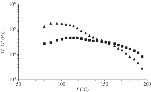
Storage (G′, triangles) and loss (G′′, squares) modulus as a function of temperature (temperature ramp test; heating scan from 80°C to 200°C at 10°C min−1; frequency = 0.5 rad s−1; strain = 0.5%).
Rheological behaviour was tested by means of frequency sweep tests at T > TCO (T = 165°C) and the results are reported in figure 3. The cross-over frequency was low (ω = 2 rad s−1), as is typical for very high molecular weight polymers (figure 3a) [17]. The PU complex viscosity as a function of frequency showed a shear thinning behaviour in a wide range of frequencies (figure 3b).
Figure 3.
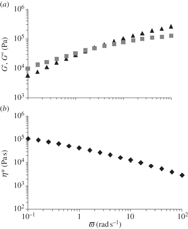
G′ (triangles) and G′′ (squares) (a) and complex viscosity (b) as a function of frequency (frequency range = 0.1–100 rad s−1; strain = 0.5%; 165°C).
The results of time sweep test (isothermal rheological characterization) are reported in figure 4. G′ and G′′ were approximately constant during the test, suggesting that samples did not undergo thermal degradation. In addition, PU stability was confirmed by the absence of significant variations in terms of the polymer molecular weight and polydispersity index after this thermo-mechanical treatment (Mn = 71 500 Da and D = 1.96; table 1).
Figure 4.
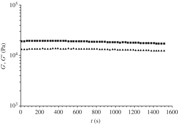
G′ (triangles) and G′′ (squares) as a function of time (time sweep test; frequency = 0.5 rad s−1; strain = 0.5%; 165°C; 30 min).
3.1.3. Thermal properties
3.1.3.1. Differential scanning calorimetry
DSC was performed to characterize the thermal properties of PU films in terms of glass transition, melting and crystallization temperatures (Tg, Tm, Tc, respectively) and melting and crystallization enthalpies (ΔHm, ΔHc, respectively). Results are shown in table 2 for each DSC scan.
Table 2.
Thermal parameters of PU measured by non-isothermal DSC analysis (first heating: from 20°C to 200°C; cooling: from 200°C to −60°C; second heating: from −60°C to 200°C; scan rate: 10°C min−1).
| first heating |
cooling |
second heating |
|||||||
|---|---|---|---|---|---|---|---|---|---|
| Tg (°C) | Tm (°C) | ΔHm (J g–1) | Tc (°C) | ΔHc (J g–1) | Tg (°C) | Tc (°C) | ΔHc (J g–1) | Tm (°C) | ΔHm (J g–1) |
| 45.4 | 76 | 2.4 | −22 | 13.6 | — | −4 | 7.2 | 39 | 24.5 |
| 155 | 2.4 | ||||||||
The DSC thermograms of PU films are reported in figure 5.
Figure 5.
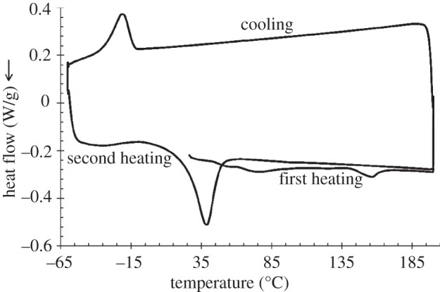
DSC thermograms of PU sample. First heating scan: heating from 20°C to 200°C at 10°C min−1 and isotherm at 200°C for 3 min; cooling scan: cooling from 200°C to −60°C at 10°C min−1 and isotherm at −60°C for 3 min; second heating scan: heating from −60°C to 200°C at 10°C min−1.
The first heating scan of the PU films showed two melting peaks at 76°C and 156°C, both characterized by a melting enthalpy of 2.4 J g–1. These two endothermic peaks are attributed to the melting of two different crystalline phases: the low-temperature melting peak is ascribable to soft segment (PCL) melting, whereas the high-temperature melting peak is associated with hard segment (BDI and chain extender) melting, as previously reported [18].
Moreover, in the first heating scan, PU films evidenced a glass transition temperature at 45.4°C, which was attributed to hard segments, in agreement with previous reports showing that the hard segment glass transition temperature is generally recorded in the 30–65°C temperature range, depending on the PU building blocks [18].
Glass transition of the PU soft segments was not detected, probably owing to its lower temperature with respect to the analysed temperature range: this hypothesis is in agreement with literature data showing that soft segments' Tg is generally measured in the −120°C to −50°C temperature interval, depending on the PU building blocks [18].
During the cooling scan, crystallization of the PCL soft segments was recorded at −22°C with a ΔHc of 7.2 J g–1. Finally, in the second heating scan, a broad exothermic peak was also observed between −32°C and 17°C, probably associated with PCL crystallization. In the same scan, one single melting peak was recorded at 39°C, with ΔHm of 24.4 J g–1, attributed to the melting of PCL soft segments. The presence of one melting peak during the second heating scan suggests that cooling and heating at 10°C min−1 did not allow hard segment organization into ordered crystalline domains.
The thermal properties of PU film samples subjected to the same thermal history of non-isothermal rheological characterization (isotherm for 10 min at 80°C followed by heating from 80°C to 200°C at 10°C min−1) were analysed. During the DSC heating scan, one endothermic peak was recorded at 158°C with ΔHm of 2.3 J g–1, which was attributed to hard segment melting. Melting enthalpy was similar to that of the corresponding endotherm in as-prepared compression moulded films (table 2), suggesting that, for PU compression-moulded samples, isothermal treatment for 10 min at 80°C (higher temperature than hard segment Tg) did not cause any increase in the degree of hard segment crystallization. This result demonstrated that data from non-isothermal rheological characterization were not altered by changes in the degree of sample crystallization during the analysis. The presence of a melting peak for PU hard segments at around 155–158°C was consistent with the results of temperature ramp rheological tests (figure 2).
During scaffold fabrication by the melt-extrusion AM technique, PU was gradually heated to complete melting (§2.3); therefore, it was kept at a higher temperature than hard segment Tg for several minutes. However, this thermal treatment is not expected to cause any modification in the hard segment melting temperature.
A processing temperature higher than the hard segment melting temperature (155°C) was selected for the fabrication of PU scaffolds by AM.
3.1.3.2. Thermogravimetric analysis
TGA was performed to measure any change in weight of PU as a function of the thermal treatment under air. The non-isothermal TGA and differential TGA (DTGA) curves of PU are reported in figure 6.
Figure 6.

TGA and DTGA curves of PU. The analysis was carried out under air in the 50–800°C temperature range at a heating rate of 10°C min−1.
The TGA and DTGA curve showed the presence of three thermal degradation steps at 250–300°C, 320–440°C and 460–560°C. A weight loss of 5%, 10% and 50% was observed at 298°C, 340°C and 390°C, respectively. The maximum rate of weight loss was reached at 392°C (at this temperature, the remaining weight was 51.6%). Around 0.55% of the initial weight was kept at 800°C.
Isothermal TGA was also performed at 165°C for 1 h under air to verify the thermal stability of PU at a higher temperature than TCO. Figure 7 shows the remaining weight percentage trend as a function of time, during isothermal TGA. After maintaining the sample at 165°C for 1 h, a weight loss of only around 1% was observed, suggesting thermal stability. No significant variations were observed in terms of the PU molecular weight and polydispersity index (Mn = 69 000 Da, D = 1.96) after this thermal treatment (table 1).
Figure 7.
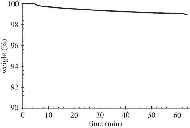
Percentage of weight as a function of time during isothermal TGA analysis at 165°C, for 1 h, under air.
3.2. Polyurethane scaffolds
Figure 8 shows FEG-SEM micrographs of porous lattice-structured scaffolds fabricated by the AM technique performed at 155°C. The uniformity of the layered pattern, with precisely aligned and regularly spaced fibres and fully interconnected inner architecture, demonstrated the suitability of this polymer to be melt-extruded in three-dimensional structures.
Figure 8.
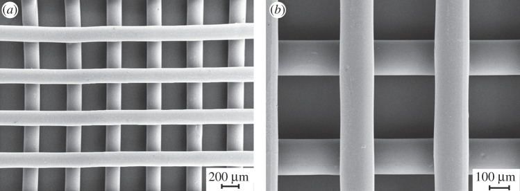
(a) FEG-SEM micrograph of a PU scaffold obtained by melt-extrusion AM; (b) higher magnification detail of the trabecular arrangement.
The results of image analysis on SEM micrographs showed good agreement between the computer-generated geometry and the obtained scaffolds. A mean fibre diameter of 152 ± 5 µm and a mean spacing of 505 ± 5 µm were measured. Scaffold height was 280 µm, suggesting interpenetration between adjacent layers of around 20 µm.
Uniaxial tensile tests were performed on scaffolds and relative mechanical parameters were measured (E = 10.2 ± 2.2 MPa; UTS = 3.3 ± 0.2 MPa; strain at UTS = 693.0 ± 15.0%). A representative tensile stress–strain curve is reported in figure 9.
Figure 9.
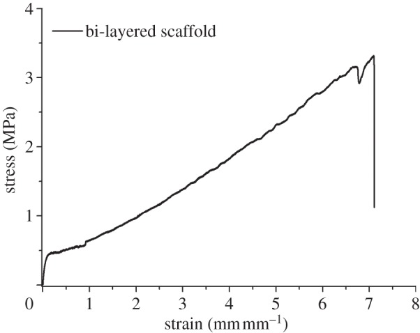
Stress–strain behaviour during uniaxial tensile test (load cell: 10 N; strain rate: 0.8 min−1).
Cyclic tensile tests (five cycles; 0–10% deformation; table 3) evidenced a permanent strain of around 2.5% after the first cycle, probably owing to chain orientation along the stress direction [19]. During the following deformation cycles, permanent strain only weakly increased up to 3.1%, suggesting an elastomeric-like behaviour of PU scaffolds. Hysteresis, representing the amount of dissipated deformation energy at each cycle, progressively decreased from around 46% to 16%. The stress at 10% deformation was approximately constant during deformation cycles (0.75–0.79 MPa).
Table 3.
Stress at 10% deformation (σ10%), residual deformation (ɛr) and energy loss for cycles calculated from uniaxial cyclic tensile tests performed on bi-layered PU scaffolds. Values were calculated using the nominal dimensions of specimens.
| cycle | σ10% (MPa) | ɛr (%) | energy loss (%) |
|---|---|---|---|
| 1 | 0.79 | 2.5 | 45.6 |
| 2 | 0.77 | 2.7 | 20.7 |
| 3 | 0.76 | 2.9 | 18.1 |
| 4 | 0.75 | 3.0 | 16.8 |
| 5 | 0.75 | 3.1 | 16.1 |
3.3. In vitro cell tests
The results of cytotoxicity tests performed on biomaterial extracts in combination with Balb/3T3 cells showed no significant toxicity, confirming the suitability of melt-extruded PU for TE applications (cell viability > 95%).
CPCs cultured in the presence of the scaffolds were observed using optical and confocal fluorescent microscopy; the latter was performed after labelling fixed cells with phalloidin and antibodies against vimentin or Ki67 (figure 10). Cells adhered to the scaffolds: after 3 days of culture, they covered the surface of the single scaffold trabeculae and reached neighbouring trabeculae as well, spreading across the pores. The proliferation-associated protein Ki67, which is expressed by cells in late G1, S, G2 and M phases, but not in resting cells in G0, was present in cell nuclei. Confocal image analysis revealed that the scaffold was entwined with cells, which stretched out in three dimensions, between the trabeculae of the same and of the adjacent layer. Owing to such cell orientation, actin filaments seemed mostly short and apparently randomly displaced in the cytoplasm, becoming evident and elongated only along the cell membrane at the surface of the trabeculae. Intermediate vimentin filaments were extending to and concentrated at the outermost boundary of the cells, presumably co-localizing with focal adhesion complexes.
Figure 10.

Optical and confocal micrographs of PU scaffold seeded with CPCs for 3 days: (a) phase contrast microscopy, scale bar 200 µm; (b–f) confocal microscopy merged images (magnification 10×) of Ki67 (b, green), actin (c,d, green), vimentin (e,f, green) and cell nuclei (b–f, red). Paired images (c,d), (e,f) show the same field focused at the level of trabeculae (c,e) or pores between layers of trabeculae (d,f).
SEM micrographs (figure 11) showed cell engraftment and evidence of cell aggregates among the scaffold trabeculae after only 7 days of culture time. After 14 days, a more uniform cell infiltration was observed. The results of cell proliferation assays are reported in figure 12. After initial engraftment (seeding efficacy on PU scaffolds after 24 h was as high as 78.2 ± 6.2%), cells cultured on PU scaffolds showed a reduced tendency to proliferate, compared with control samples.
Figure 11.
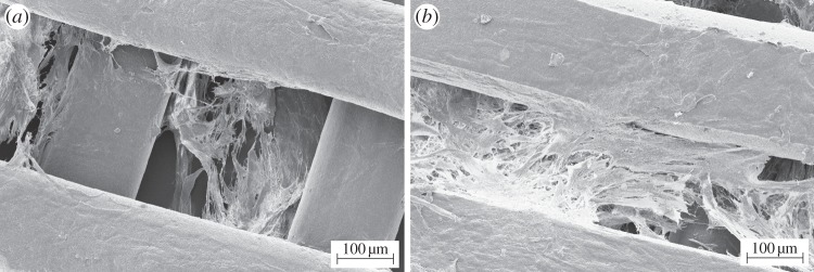
SEM micrographs of PU scaffolds cultured with human CPCs for (a) 7 and (b) 14 days.
Figure 12.
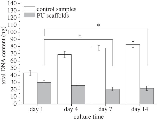
Proliferation of human CPCs in contact with PU scaffolds for 1, 4, 7 and 14 days assessed by measuring total DNA content. Asterisk (*) denotes significant difference (p < 0.05). Filled bars denote PU scaffolds; open bars denote control samples.
4. Discussion
In this work, a biocompatible PU was synthesized from degradable and biocompatible building blocks: PCL diol, BDI and l-lysine ethyl ester dihydrochloride chain extender. This formulation was previously demonstrated to produce biomaterials as optimal substrates for myoblast adhesion, spreading and proliferation [11]. In this work, the synthesis method was slightly modified by the introduction of additional purification steps, to obtain a polymer with a higher molecular weight, in order to improve melt-extrusion.
ATR-FTIR analysis confirmed the success of the synthesis of PU, as the characteristic absorption bands of the urethane groups were observed in the PU ATR-FTIR spectrum (figure 1); in addition, the typical absorption band of unreacted diisocyanate (at 2200 cm−1) was not detectable, confirming complete conversion of the monomers.
PUs are block copolymers consisting of soft and hard domains with a different Tg. PU soft segments were based on semi-crystalline PCL chains having a Tg lower than −60°C, whereas PU hard segments consisted of diisocyanate and chain extender blocks, showing a Tg of around 45°C. DSC analysis of PU compression-moulded specimens showed that both soft and hard segments partially crystallized during sample preparation (figure 2; first heating). However, after the first DSC heating and subsequent cooling, further reheating only showed an endotherm associated with soft segment melting (figure 2; second heating).
During the rheological temperature ramp test, the compression-moulded samples were kept at 80°C for 10 min, followed by a heating step at 10°C min−1 from 80°C to 200°C. As this thermal treatment could ideally promote hard segment crystallization further, a DSC analysis simulating the rheological temperature ramp test was performed on compression-moulded specimens. However, a comparison between melting enthalpy data of hard segments in compression-moulded specimens (table 2, first heating) and samples analysed by the DSC test simulating the rheological temperature ramp experiment showed similar values, suggesting that the degree of hard segment crystallinity did not change during the rheological analysis. Importantly, the rheological temperature ramp test evidenced that G′ was lower than G′′ at a higher temperature than 154°C (figure 2), which confirmed PU melt processability at higher temperature, in agreement with the DSC results.
The melt processing temperature is limited by the occurrence of polymer thermal degradation phenomena, which can be analysed through TGA. In this work, non-isothermal TGA was carried out under air to mimic the processing conditions at which the scaffolds were fabricated. PU showed a weight loss of 5% at approximately 300°C, indicative of a large temperature processing range (figure 6). Moreover, the measured degradation temperature was in agreement with previous literature reports on other PUs [20–22].
A processing temperature of 155°C was thus proposed for melt-extrusion AM of PU. The thermo-mechanical stability of PU was investigated at a 10°C higher temperature (165°C). Isothermal TGA performed at 165°C for 1 h under air evidenced that PU underwent a weight loss of only 1% (figure 7) and negligible variations in molecular weight and polydispersity index (table 1), suggesting its thermal stability under the processing conditions. A time sweep test was also carried out at 165°C under air as a tool to analyse PU thermo-mechanical stability under shear stresses. G′ and G′′ did not change as a function of time (figure 4) and the molecular weight of the tested samples did not significantly decrease compared with the synthesized PU (table 1), suggesting the possibility to melt process PU at 165°C without the occurrence of significant degradation phenomena. Finally, a frequency sweep test carried out at 165°C evidenced a pseudoplastic behaviour for the viscous polymer melt (figure 3), which is fundamental for melt extrusion of a high molecular weight polymer.
On the basis of the performed characterization, PU was melt processed at 155°C without the occurrence of thermo-mechanical degradation events. The melt-extrusion AM technique allows the preparation of scaffolds with controlled and reproducible geometry. A melt processing temperature of 155°C was found to be optimal for the fabrication of bi-layered scaffolds with a 0°/90° lay-down pattern (figure 8). Thanks to the polymer's high viscosity and rapid solidification rate, each extruded layer retained its shape, leading to a consistent three-dimensional structure with desired pore size and fully interconnected pore volume.
To the authors’ knowledge, melt-extrusion techniques have never been applied for the preparation of myocardial scaffolds. A similar AM technique, pressure-assisted micro-syringe (PAM), has been previously proposed for the fabrication of scaffolds for myocardial regeneration, based on the extrusion of polymer viscous solutions in a volatile solvent [23–25]. However, the melt-extrusion AM technique has several advantages over PAM: (i) it avoids the use of an organic solvent; (ii) melt viscosity is presumably higher than solution viscosity, allowing the preparation of scaffolds which closely reproduce the computer-designed architecture; and (iii) owing to the higher viscosity of the melt, melt-extrusion AM does not require the use of a second polymer for layer-by-layer deposition of three-dimensional scaffolds. In analogy to the PAM technique, the optimization of scaffold design fabricated by melt-extrusion AM can lead to anisotropic mechanical properties and topological cues suitable for CPC differentiation [23].
In this preliminary work, scaffolds were prepared with isotropic geometrical properties. Despite the standing debate on the optimal scaffold design in the field of cardiac TE, the geometry of the fabricated scaffolds (fibre size of 152 ± 5 μm and fibre spacing of 505 ± 5 μm) may satisfy the requirements for long-term cell survival [26]. Melt-extrusion AM allows a fine control over architectural features: scaffolds with the desired pore size and porosity values can be additively manufactured on the basis of specific requirements (such as mechanical and biological ones). Previous literature data have demonstrated that optimal scaffolds for myocardial TE should display elastomeric properties in analogy with native heart tissue [3]. It is known that PUs can exhibit elastomeric mechanical properties owing to: (i) the presence of soft and hard segments with lower and higher Tg than the temperature of use, respectively; (ii) a relatively low degree of crystallinity; and (iii) the presence of flexible chains in the amorphous regions, which can undergo rapid disentanglement and entanglement recovery during deformation cycles. In this work, uniaxial tensile and cyclic deformation tests (figure 9 and table 3) showed that bi-layered PU scaffolds possessed an elastomeric-like mechanical behaviour. After five deformation cycles (at 0–10% strain), a permanent deformation of around 3.1% was recorded, owing to chain orientation along the stress direction occurring mostly during the first deformation cycle (2.5% permanent strain) [19].
Human-derived CPCs were found to firmly adhere to the scaffolds, keeping viability and showing a proliferative behaviour and a spreading morphology after 3 days of culture time (figure 10). In vitro cell tests performed for longer times (7–14 days) showed cell engraftment among the scaffold trabeculae (figure 11). However, CPCs cultured on bi-layered scaffolds did not show a proliferative behaviour when compared with control samples, after 1–14 days of culture time (figure 12). In the future, differentiation markers of CPCs cultured on the scaffolds will be evaluated to correctly interpret these results.
Moreover, further optimization of scaffold geometry (in terms of porosity degree, pore size, mechanical properties) and surface chemical composition (by surface functionalization with bioactive cardiac ECM proteins) will be carefully considered to allow the design of scaffolds able to specifically interact with CPCs.
5. Conclusion
A tailor-made design of the scaffold material and architecture is of crucial importance in order to obtain scaffolds with biomimetic properties, properly interacting with cells and driving tissue regeneration. In this context, PUs are interesting materials, owing to their block structure which allows the design of polymers with proper characteristics depending on final requirements.
In this work, a cytocompatible high molecular weight PU was proposed for the preparation of scaffolds for myocardial TE by melt-extrusion AM. Rheological and calorimetric analyses evidenced the possibility of PU melt processing at temperatures higher than 155°C. After verifying the absence of significant polymer thermo-mechanical degradation phenomena at 165°C by isothermal TGA and rheological time sweep tests, a temperature of 155°C was found to be optimal for the fabrication of scaffolds by melt-extrusion AM. The melt-extrusion technique was proposed here as a method to design scaffolds for myocardial TE. Bi-layered scaffolds with a 0°/90° lay-down pattern were fabricated with a highly reproducible quality of the computer-designed architecture, demonstrating PU suitability for melt processing. Scaffolds showed an elastomeric-like behaviour: they evidenced a low permanent deformation (approx. 2.5%) during the first tensile strain cycle (0–10% deformation) and an almost complete deformation recovery in the following tensile strain cycles (0.1–0.2% permanent deformation at each following cycle).
Human-derived CPCs were found to adhere on the scaffolds, showing a spread geometry and retaining viability. However, CPCs did not proliferate in contact with scaffolds after 1–14 days of culture time. Optimization of scaffold geometry and surface chemical composition is in progress to obtain scaffolds with suitable properties for myocardial TE.
Acknowledgements
FIRB 2010 Project ‘Bioartificial materials and biomimetic scaffolds for a stem cells-based therapy for myocardial regeneration’ (grant no. RBFR10L0GK) financed by MIUR (Italian Ministry of Education University and Research) is acknowledged.
References
- 1.Silvestri A, Boffito M, Sartori S, Ciardelli G. 2013. Biomimetic materials and scaffolds for myocardial tissue regeneration. Macromol. Biosci. 13, 984–1019. ( 10.1002/mabi.201200483) [DOI] [PubMed] [Google Scholar]
- 2.Gaballa MA, Sunkomat JN, Thai H, Morkin E, Ewy G, Goldman S. 2006. Grafting an acellular 3-dimensional collagen scaffold onto a non-transmural infarcted myocardium induces neo-angiogenesis and reduces cardiac remodeling. J. Heart Lung Transplant 25, 946–954. ( 10.1016/j.healun.2006.04.008) [DOI] [PubMed] [Google Scholar]
- 3.Webb AR, Yang J, Ameer GA. 2004. Biodegradable polyester elastomers in tissue engineering. Expert Opin. Biol. Ther. 4, 801–812. ( 10.1517/14712598.4.6.801) [DOI] [PubMed] [Google Scholar]
- 4.Pittenger MF, Martin BJ. 2004. Mesenchymal stem cells and their potential as cardiac therapeutics. Circ. Res. 95, 9–20. ( 10.1161/01.RES.0000135902.99383.6f) [DOI] [PubMed] [Google Scholar]
- 5.Gimble JM, Katz AJ, Bunnell BA. 2007. Adipose-derived stem cells for regenerative medicine. Circ. Res. 100, 1249–1260. ( 10.1161/01.RES.0000265074.83288.09) [DOI] [PMC free article] [PubMed] [Google Scholar]
- 6.Boyle AJ, Schulman SP, Hare JM. 2006. Stem cell therapy for cardiac repair ready for the next step. Circulation 114, 339–352. ( 10.1161/CIRCULATIONAHA.105.590653) [DOI] [PubMed] [Google Scholar]
- 7.Castaldo C, et al. 2008. CD117-positive cells in adult human heart are localized in the subepicardium, and their activation is associated with laminin-1 and alpha6 integrin expression. Stem Cells 26, 1723–1731. ( 10.1634/stemcells.2007-0732) [DOI] [PubMed] [Google Scholar]
- 8.Cesselli D, et al. 2011. Effects of age and heart failure on human cardiac stem cell function. Am. J. Pathol. 179, 349–366. ( 10.1016/j.ajpath.2011.03.036) [DOI] [PMC free article] [PubMed] [Google Scholar]
- 9.D'Amario D, et al. 2011. Functionally competent cardiac stem cells can be isolated from endomyocardial biopsies of patients with advanced cardiomyopathies. Circ. Res. 108, 857–861. ( 10.1161/CIRCRESAHA.111.241380) [DOI] [PMC free article] [PubMed] [Google Scholar]
- 10.Di Meglio F, Castaldo C, Nurzynska D, Romano V, Miraglia R, Bancone C, Langella G, Vosa C, Montagnani S. 2010. Epithelial–mesenchymal transition of epicardial mesothelium is a source of cardiac CD117-positive stem cells in adult human heart. J. Mol. Cell. Cardiol. 49, 719–727. ( 10.1016/j.yjmcc.2010.05.013) [DOI] [PubMed] [Google Scholar]
- 11.Sartori S, Boffito M, Serafini P, Caporale A, Silvestri A, Bernardi E, Sassi MP, Boccafoschi F, Ciardelli G. 2013. Synthesis and structure–property relationship of polyester-urethanes and their evaluation for the regeneration of contractile tissues. React. Funct. Polym. 73, 1366–1376. ( 10.1016/j.reactfunctpolym.2013.01.006) [DOI] [Google Scholar]
- 12.French KM, Boopathy AV, DeQuach JA, Chingozha L, Lu H, Christman KL, Davis ME. 2012. A naturally derived cardiac extracellular matrix enhances cardiac progenitor cell behavior in vitro. Acta Biomater. 8, 4357–4364. ( 10.1016/j.actbio.2012.07.033) [DOI] [PMC free article] [PubMed] [Google Scholar]
- 13.Rechichi A, Ciardelli G, D'Acunto M, Vozzi G, Giusti P. 2008. Degradable block polyurethanes from nontoxic building blocks as scaffold materials to support cell growth and proliferation . J. Biomed. Mater. Res. A 84, 847–855. ( 10.1002/jbm.a.31349) [DOI] [PubMed] [Google Scholar]
- 14.Rainer A, Giannitelli SM, Accoto D, De Porcellinis S, Guglielmelli E, Trombetta M. 2012. Load-adaptive scaffold architecturing: a bioinspired approach to the design of porous additively manufactured scaffolds with optimized mechanical properties. Ann. Biomed. Eng. 40, 966–975. ( 10.1007/s10439-011-0465-4) [DOI] [PubMed] [Google Scholar]
- 15.Giannitelli SM, Accoto D, Trombetta M, Rainer A. 2013. Current trends in the design of scaffolds for computer-aided tissue engineering. Acta Biomater. ( 10.1016/j.actbio.2013.10.024) [DOI] [PubMed] [Google Scholar]
- 16.Nurzynska D, et al. 2013. Cardiac primitive cells become committed to a cardiac fate in adult human heart with chronic ischemic disease but fail to acquire mature phenotype: genetic and phenotypic study. Basic Res. Cardiol. 108, 320–333. ( 10.1007/s00395-012-0320-2) [DOI] [PubMed] [Google Scholar]
- 17.Ferry JD. 1980. Viscoelastic properties of polymers, 3rd edn New York, NY: Wiley. [Google Scholar]
- 18.D'Arlas DF, Rueda L, De La Caba K, Mondragon I, Eceiza A. 2008. Microdomain composition and properties differences of biodegradable polyurethanes based on MDI and HDI. Polym. Eng. Sci. 48, 519–529. ( 10.1002/pen.20983) [DOI] [Google Scholar]
- 19.Christenson EM, Anderson JM, Hiltner A, Baer E. 2005. Relationship between nanoscale deformation processes and elastic behavior of polyurethane elastomers. Polymer 46, 11 744–11 754. ( 10.1016/j.polymer.2005.08.083) [DOI] [Google Scholar]
- 20.Sarkar D, Yang JC, Gupta AS, Lopina ST. 2009. Synthesis and characterization of L-tyrosine based polyurethanes for biomaterial applications. J. Biomed. Mater. Res. A 90, 263–271. ( 10.1002/jbm.a.32095) [DOI] [PubMed] [Google Scholar]
- 21.Spagnuolo M, Liu L. 2012. Fabrication and degradation of electrospun scaffolds from l-tyrosine-based polyurethane blends for tissue engineering applications. ISRN Nanotechnol. 2012, 627420 ( 10.5402/2012/627420) [DOI] [Google Scholar]
- 22.Sarkar D, Yang JC, Lopina ST. 2008. Structure-property relationship of L-tyrosine-based polyurethanes for biomaterial applications. J. Appl. Polym. Sci. 108, 2345–2355. ( 10.1002/app.27637) [DOI] [Google Scholar]
- 23.Forte G, et al. 2008. Criticality of the biological and physical stimuli array inducing resident cardiac stem cell determination. Stem Cells 26, 2093–2103. ( 10.1634/stemcells.2008-0061) [DOI] [PubMed] [Google Scholar]
- 24.Pagliari Vilela-Silva AC, et al. 2011. Cooperation of biological and mechanical signals in cardiac progenitor cell differentiation. Adv. Mater. 23, 514–518. ( 10.1002/adma.201003479) [DOI] [PubMed] [Google Scholar]
- 25.Vozzi G, et al. 2008. PAM-microfabricated polyurethane scaffolds: in vivo and in vitro preliminary studies. Macromol. Biosci. 8, 60–68. ( 10.1002/mabi.200700214) [DOI] [PubMed] [Google Scholar]
- 26.Chen QZ, Harding SE, Ali NN, Lyon AR, Boccaccini AR. 2008. Biomaterials in cardiac tissue engineering: ten years of research survey. Mater. Sci. Eng. R59, 1–37. ( 10.1016/j.mser.2007.08.001) [DOI] [Google Scholar]