Abstract
In the present study, we introduce Poly(vinylidene fluoride) (PVDF) nanofibers containing nickel (Ni) nanoparticles (NPs) as a result of an electrospinning. Typically, a colloidal solution consisting of PVDF/Ni NPs was prepared to produce nanofibers embedded with solid NPs by electrospinning process. The resultant nanostructures were studied by SEM analyses, which confirmed well oriented nanofibers and good dispersion of Ni NPs over them. The XRD results demonstrated well crystalline feature of PVDF and Ni in the obtained nanostructures. Physiochemical aspects of prepared nano-structures were characterized for TEM which confirmed nanofibers were well-oriented and had good dispersion of Ni NPs. Furthermore, the prepared nano-structures were studied for hydrogen production applications. Due to high surface to volume ratio of nanofibers form than the thin film ones, there was tremendous increase in the rate of hydrogen production. Overall, results satisfactorily confirmed the use of these materials in hydrogen production.
Keywords: Nanofibers, Nanoparticles, Films, Electrospinning
1. INTRODUCTION
In recent years, use of various sources of energy had been utilized by human society, so to be utilized in the various comforts of life. There are various means of obtaining energy from the natural and artificial resources. Among the various forms of energy, hydrogen is considered as a wonderful means of energy harvesting alternative. The production of energy by direct water splitting without any by-products is one of potential alternatives to hydrogen fuel for future energy supply.1–2 In order to over come the demand for hydrogen production many methods had been devised, such methods includes; reforming of natural gas,3–4 coal gasification,5 biomass pyrolysis and gasification,6 hydrolysis of chemical hydrides7, 8 and electrolytic or photocatalytic water splitting.1–2 Hydrogen production by water splitting using electrolysis of alkaline solution is commercially done, although the efficiency is low. Higher efficiencies are achieved using polymer electrolyte membrane electrolyzer and by photovoltaic reaction. Recently, a growing interest has been seen in hydrogen storage and generation using chemical hydride materials such as lithium hydride (LiH),9 sodium aluminum hydride (NaAlH4),10 lithium borohydride (LiBH4),11 and sodium borohydride (NaBH4).12–14 Many types of chemical hydrides have been used as hydrogen storage and generation materials. NaBH4 is more favorable because of its high hydrogen density, stability in alkaline solution,15 pure hydrogen generation,16 and recycling of the by-products.17 The governing reaction for hydrogen storage and generation is given as:
| (1) |
Presently, various catalysts have been developed such as ruthenium,18, 19 platinum,20, 21 iron,22 cobalt, nickel,13, 14 palladium,23 and copper12 are being used to enhance the rate of hydrogen generation by hydrolysis of NaBH4, Though novel metals, such as platinum and ruthenium as catalysts may provide higher hydrogen production rate,24 but they have many limitations in real application due to high costs and short lifetime.14 Therefore, normal metals have been mainly studied as catalysts for the hydrolysis of chemical borohydride for hydrogen generation with relatively high rate and stability. Cobalt boride powder,25, 26 cobalt supported by γ-Al2O3,27 cobalt or cobalt phosphorous deposited on copper substrate,28 and nickel, as economical metals, have been used for hydrogen generation by hydrolysis of NaBH4.
Electrospinning technique has been paid a considerable attention due to production fibers having diameter in the range of few microns to nanometer level and for economical aspect.29–30 In a typical electrospinning process, electrostatically driven polymer jet is ejected from polymer solution which undergoes bending instability wherein the solvent evaporates and ultra fine stretched fiber are deposited on the grounded collector.31–32 Consequently, the nanofibers obtained by this technique give large surface area compared to other nanoparticulate forms.
In this paper, we introduce a simple and feasible methodology to fabricate three potentially effective forms of nano-catalysts, for instance; pristine poly(vinylidene fluoride) (PVDF) nanofibers, modified PVDF nanofibers containing nickel (Ni) nanoparticles (NPs) and PVDF films containing Ni NPs. To produce such robust and super catalyst organic and inorganic blends, PVDF was used as material of choice, because of its excellent properties like as its high mechanical strength and good resistance to solvents, acids, and bases.33 With this impression PVDF had been selected for the incorporation of Ni NPs inside, in the form of polymeric nanofibers and thin films. The prepared nanocatalysts had been characterized for various states of art techniques like SEM, SEM-EDX, TEM and XRD. Furthermore, these prepared materials had been tested for the production of hydrogen by using hydrolysis of NaBH4. Overall, the obtained result demonstrated the wellness of PVDF nanofibers containing Ni NPs as efficient nanocatalysts for future coming catalysts.
2. EXPERIMENTAL DETAILS
2.1. Materials
Poly(vinylidene fluoride) PVDF (Solef 6010) was supplied by solvay. Nickel nanopowder <100 nm, 99.9% pure was purchased from Aldrich USA. Sodium borohydride was purchased from Samchun chemical, Korea. N, N-dimethylformamide (DMF) Showa Chemicals Ltd., Japan were used as solvents without further purification.
2.2. Characterization
The morphology of the nanostructures had been analyzed by JEOL JSM-5900 scanning electron microscope, JEOL Ltd., Japan. Information about the phase and crystallinity of obtained nanofibers and micro-particulate was done by using X-ray diffractometer (XRD, Rigaku Co., Japan) with Cu Kα (λ = 1.540 Å) radiation over Bragg angle ranging from 10 to 90°. Transmission electron microscopy (TEM) was done by JEOL JEM 2010 operating at 200 kV, JEOL Ltd., Japan.
2.3. Procedure
2.3.1. Fabrication of Nanofibers by Electrospinning
The electrospinning process was utilized to produce PVDF nanofibers containing Ni NPs. Typically, a 16 wt% PVDF solution was prepared by dissolving PVDF in a mixture of DMF and acetone (DMF/acetone) 2:1, (volume ratio) with stirring for 12 h at 80 °C. To fabricate the Ni modified nanofibers a colloidal solution containing Ni NPs was prepared to produce these nanofibers. Briefly, Ni NPs weighing in 0.5 g, were added with previously transparent solutions of PVDF. Afterwards, this solution was homogeneously mixed under stirred conditions for 10 minutes and further on, these solutions were kept ready for electro-spinning. A high voltage power supply (CPS-60 K02V1, Chungpa EMT Co., South Korea), capable of generating voltages up to 60 kV, was used as a source of electric field for spinning of polymer solution. These solutions were supplied through a plastic syringe attached to a capillary tip. The wire originating from positive electrode (anode) connected with copper pin was inserted into the solution and a negative electrode (cathode) was attached to a metallic collector. In this regard, the Scheme 1 represents the conceptual illustration for the used electrospinning set-up. The solutions were electrospun at 15 kV and 15 cm working distance (the distance between the needle tip and the collector). The as-spun fibers were lastly dried for 24 h at 80 °C under vacuum in presence of P2O5, so as to remove the residual solvents.
Scheme 1.
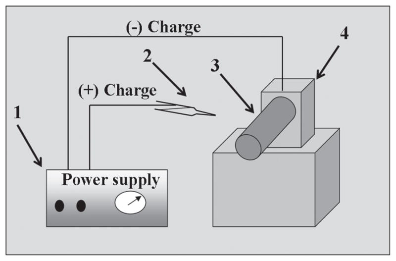
The schematic illustration of a simple electrospinning spinning apparatus: (1) dc power supply (2) Syringe (3) Rotating collector (4) Electric motor.
2.3.2. Fabrication of PVDF Films Containing Ni NPs
To fabricate the PVDF films containing Ni NPs, following methodology was adopted. Briefly, Ni NPs weighing in 0.5 g were added with previously prepared 16 wt% solution of PVDF in a mixture of DMF and acetone (DMF/acetone) 2:1, (volume ratio) with stirring for 12 h at 50 °C. Afterwards, these solutions were homogeneously mixed under stirred conditions for 10 minutes. However, instead of electrospinning as previously described, the samples were poured on glass slides to prepare thin films and allowed to air dry. It is noteworthy, to mention that same concentration of polymers and metal catalysts were kept in making the films, so as to have comparison during the hydrogen production. Finally, these samples were vacuously dried under vacuum at 80 °C for 48 hours in presence of P2O5, to completely remove the residual solvents from the preparation media.
2.3.3. Hydrogen Production Studies
All the samples were checked for the catalytic activity for in-situ hydrolysis of NaBH4 by keeping same conditions, so as to find out the difference in their catalytic activities. Typically, each 50 mg of samples were placed in a specially designed tight sealed flask which contains 50 ml of solution containing 50 mg of NaBH4 at constant temperature of (25 °C). The catalytic performances were compared for the hydrogen production from hydrolysis of NaBH4. Briefly, the reaction proceeded at a stirring rate of 1000 rpm and the amount of hydrogen generated with time was measured immediately after all the components were added. The amount of hydrogen generated in volume was measured by water displacement method,34 where the volume of hydrogen is equal to that of the displaced water whose weight was recorded by a balance. The balance connected with a computer which was installed with the software of ‘Balance Talk,’ can read the balance weight automatically.
3. RESULTS AND DISCUSSION
As aforementioned, three types of catalysts were fabricated in this study. For each formulation, the obtained electron microscopic images are represented in Figure 1. As labeled in Figure 1(A), this figure shows the obtained morphology of pristine nanofibers after electrospinning. In is noteworthy, to mention that electrospinning of pristine PVDF solution leads to produce the smooth, uniform and bead free nanofibers. Further on, from this image we can see persistent nanofibrous morphology in accordance with our previously established reports.35 On the contrary, SEM images of it counterparts (i.e., nanofibers which contains Ni NPs) is presented in Figure 1(B). The morphological appearance of this combination has not been affected by addition of Ni NPs. Considering, the size of Ni NPs, which less than 100 nm, these NPs can easily fit inside the nanofibers. Overall, the electrosinning resulting from the colloidal solution of PVDF containing Ni NPs yielded nanofibers with good acceptability for nanofibrous shape. Moreover, a schematic presentation for the fabrication of nanofibers has been introduced in Scheme 2. Briefly, the first step of this scheme includes the preparation of colloidal solution containing Ni NPs. After this step, the prepared solution is electrospun to form PVDF nanofibers containing Ni NPs. Finally, the followed procedure leads to produce the product, which will give nanofibers containing Ni NPs within them. On the other hand, the Figure 1(C) shows the morphology of PVDF films containing Ni NPs. From this image, it can be seen that formation thin film containing Ni NPs had been accomplished. The presence of particles in the polymer film can be seen as in bright in color, than the present dark background. It can be also observed that the presence of spherical Ni NPs are predominantly present over the central area of the image, and these NPs occur with wide range of diameters ranging from (20 to 100 nm).
Fig. 1.

The scanning electron microscopic images of the obtained nano-catalysts. Images of the pristine PVDF nanofibers (A), images of the PVDF nanofibers containing Ni NPs (B), and PVDF films containing Ni NPs (C).
Scheme 2.
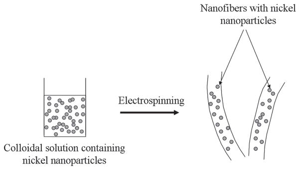
The systematic presentation for this novel strategy to represent the fabrication of PVDF nanofibers containing Ni NPs.
To ensure that the added NPs are really present over polymeric nanofibers and films, SEM-EDX analysis was utilized for all the aforementioned combinations. In this regard, the results are presented in Figure 2. As shown in Figure 2(A), and its corresponding EDX data, originating from the marked area. As indicated, from the corresponding EDX, the C and F peaks represents the presence of carbon and fluorine. The evolution of these peaks is due to the fact, because PVFD consists of these two molecular species at the elemental level, so apparent presence of C and F is quit acceptable. While as, the EDX data of its counter part which contains certain amount of Ni NPs is presented in the Figure 2(B). From its EDX spectra we can clearly find, that in addition to peaks for PVDF, there is a presence of additional Ni peaks. These results clearly demonstrate that small sized NPs can be easily carried inside the nanofibres during the process of electrospinning. On the other hand, EDX data originating from the PVDF films containing Ni NPs is presented in Figure 2(C). From this figure, it can be seen that the peaks present over there are exactly matching with the nanofiber composition containing Ni NPs (i.e., in case of Fig. 2(B)), since both the formulation have equal contents of precursors (i.e., PVDF and Ni NPs), used in same amounts that was used in formation of original colloidal solutions. Therefore, the presence of C, F and Ni at same intensity levels is acceptable from the EDX data. The presence of these peaks is clearly evident from the Figure 2(C), which shows the obtained results.
Fig. 2.
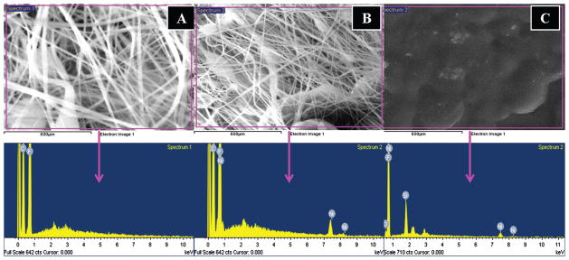
SEM images equipped with EDX results. The area EDX of the pristine PVDF nanofibers and its corresponding data (A), area EDX of the modified PVDF nanofibers containing Ni NPs and its corresponding data (B) and the area EDX of the modified PVDF films containing Ni NPs and its corresponding data (C).
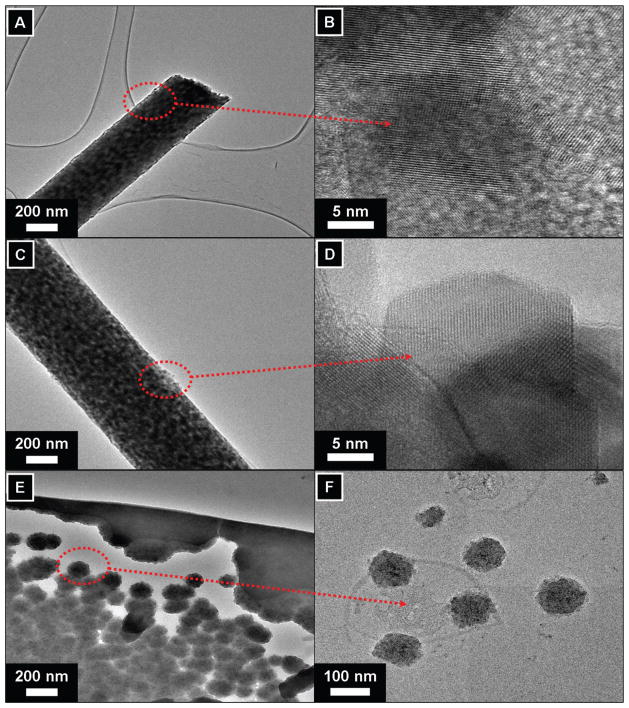
It is well known fact that transmission electron microscope (TEM) analysis can be utilized to differentiate between the nature of two different crystalline materials with regard to their different crystalline patterns. To investigate this phenomenon for the case of nanofibers, the sampling was achieved by placing the TEM grid very close to the tip opening of the syringe needle for a few seconds during the process of electrospinning. Further on, the samples were dried under vacuum and observed under TEM. To find out crystalline features of samples, the data originating from the pristine nanofibers is presented in Figures 3(A and B). It can be seen that the morphology of individual nanofiber is in constant agreement with the morphology as was observed from SEM images (i.e., Fig. 1(A)). In addition to low magnification image of the pristine nanofiber, the HR-TEM image of the nanofiber is presented in Figure 3(B). From the HR-TEM image as indicated by arrow from the former image, it can be maintained that there are no dislocation of crystal lattice and crystal planes are arranged in a linearly unique patterns, as of considering the nature of pure PVDF.36 Figure 3(C), pictures the low magnification TEM images of the nanofibers containing Ni NPs. As pictured, it can be clearly seen that Ni NPs are predominately present on the nanofiber surfaces. These Ni NPs, can be seen as darker in color than the main PVDF nanofiber. Moreover, as indicated by arrows, the HR-TEM of the marked area from former figure is presented in Figure 3(D). It can be maintained that Ni NPs are cubic shape, and are ranging in the diameter of 20 to 25 nm. It can be observed that Ni NPs have good atomic arrangement and the atoms can be seen to be uniformly arranged, which indicate there good crystallinity. It is noteworthy to mention, that in case of SEM analyses presence of Ni NPs were not so obvious, because the rationale is due high intensity electron beam of TEM which can differentiate the internal as well external contents of the crystalline materials, which former can not do, due to its poor resolution. On the other hand, low and high magnification TEM images of the PVDF film containing Ni NPs is shown in (Figs. 3(E and F)). It can be seen that the Ni NPs are predominately present over the films. The presence of spherical Ni NPs can be observed from both the high and low magnification images. From these observations it reveals that sizes of the NPs ranges about 10 to 100 nm, as were used in making the original solutions, while electrspinning. Furthermore, these results are in well consistent with SEM observations (Fig. 1(C)), were the NPs were seen on dark background.
Fig. 3.
Transmission electron microscopic images of nano-catalysts. Pristine nanofibers in low magnification (A), the HRTEM images of the pristine nanofiber as marked by arrow (B). The low magnification images of the modified nanofibers containing Ni NPs (C), the HR-TEM images of the corresponding former figures (D). The low magnification images of the PVDF film containing Ni NPs (E), the HR-TEM images of the corresponding former figures (F).
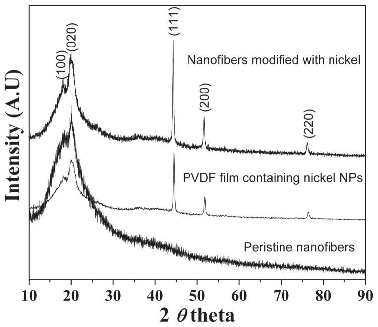
Figure 4, shows the XRD pattern of obtained nano-structures. In all these produced combinations, different diffraction peaks consisting of both PVFD and Ni were observed. In more details, one can see the diffraction peaks at 2θ values at 18.15, 20.26 and 22.53° correspond to the crystal planes of (020), (110) and (021), respectively which indicate the presence of pure PVFD.37 While as, in case of other two combinations (i.e., PVDF nanofibers and PVDF films containing Ni NPs) in addition to the PVDF peaks, these combinations possess the some additional extra peaks. These peaks are exactly matching at 2θ values of Ni at 17.72, 20.11, 44.23, 51.68 and 76.29° corresponding to the crystal planes of (100), (020), (111), (200) and (220) which indicate the presence of well received Ni NPs inside the PVDF nanofibers and films.38 It is interesting to note, that the intensities of Ni peaks present in these two mentioned combinations were same, because due to the same amount of precursor used in the original colloidal gel required to produce the nano-composites.
Fig. 4.
XRD results of the different nano-composites.
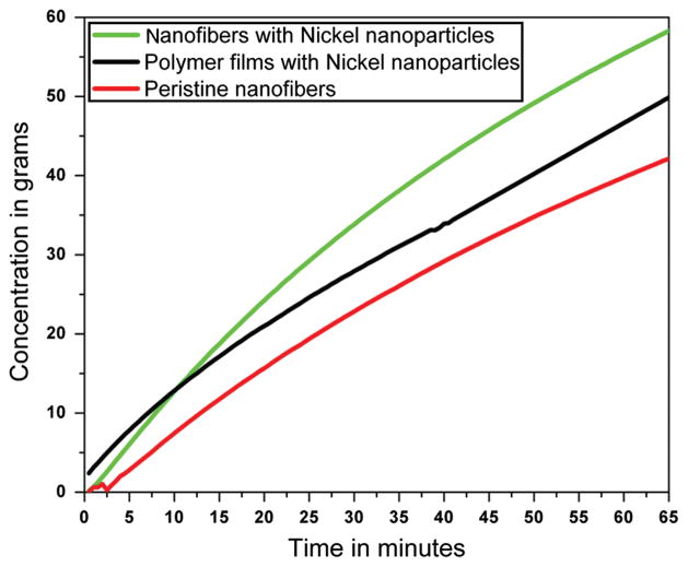
Figure 5, shows the results obtained after testing their potential as a catalyst for hydrogen production. From these results, it can be seen that hydrogen production by three different combinations induced good and reasonable properties to enhance the hydrogen production. Overall, from all the used combinations the hydrogen production was in the range of 40 to 60 grams. In more details, it can be observed that the highest amount of hydrogen production is shown by the modified nanofibers containing Ni NPs, which is later on followed by PVDF films containing Ni NPs, and further on is followed, by pristine nanofibers. The main reason for high amount of hydrogen production from Ni modified is due to the presence of Ni NPs, which indeed imparts the catalytic properties to these nano structures. While as, the pristine PVDF nanofiber is deficient of Ni NPs, so do not show much production compared with the former two combinations. It is noteworthy, to mention that the amount of hydrogen produced by pristine nanofibers which is Ni free, is due to the presence of original NaBH4 in the processing media, so therefore, as shown in the this figure (Fig. 5), the 35 grams of hydrogen produced is due basic function of NaBH4. Moreover, the highest producing combination (i.e., modified nanofibers containing Ni NPs) leads to produce more hydrogen than its counter part (PVDF films containing Ni NPs). Being, having the same amount of manufacturing raw materials, still the nanofibers containing Ni NPs combination produced high amounts of hydrogen (i.e., 60 grams). The accepted reason for this is more the surface to volume ratio of nanofibers than films.39 Overall, our observations are in consistence with those results, where high surface to volume ratio plays an key role to dramatically influence the properties of materials.40
Fig. 5.
The hydrogen production studies by various nano-composites.
4. CONCLUSION
In conclusion, we were able to fabricate three combinations of nano-catalysts. All the three combinations can be well characterized by various state of art technique. Electrospinning of a colloid comprised of the prepared PVDF and Ni NPs colloidal-solutions can lead in the production of nanofibers that include captured NPs. The SEM and EDX can be invoked to differentiate between pristine and Ni loaded nanofibers. TEM can be used to characterize the appearance of Ni NPs over the nanofiber and films. Due to high surface to volume ratio of nano-fibirous form, can lead to produce more hydrogen than the other forms. Overall, the fabricated materials could be an eye opening for future issues in the hydrogen production.
Acknowledgments
This work was supported by Priority Research Centers Program through the National Research Foundation of Korea (NRF) funded by the Ministry of Education, Science and Technology (2010-0028300). Dr. Faheem A. Sheikh is also thankful for partial financial support for this work from NIH-NIGMS-NIA grant # 1SC2AG036825-01.
References and Notes
- 1.Battista RJ, Garelli FM. J Power Sources. 2006;155:478. [Google Scholar]
- 2.Miland H, Glockner R, Taylor P, Aaberg RJ, Hagen G. Int J Hydrogen Energy. 2006;31:1215. [Google Scholar]
- 3.Farrauto R. J Appl Catal B. 2005;56:3. [Google Scholar]
- 4.Heinzel A, Vogel B, Hubner P. J Power Sources. 2002;105:202. [Google Scholar]
- 5.Stiegel GJ, Ramezan M. Int J Coal Geol. 2006;65:173. [Google Scholar]
- 6.Iojoiu EE, Domine ME, Davidian T, Guilhaume N, Mirodatos C. Appl Catal A. 2007;323:147. [Google Scholar]
- 7.Amendola SC, Goldman SLS, Janjua MS, Spencer NC, Kelly MT, Petillo PJ, Binder M. Int J Hydrogen Energy. 2000;25:969. [Google Scholar]
- 8.Kim JH, Kim KT, Kang YM, Kim HS, Song MS, Lee YJ, Lee PS, Lee JY. J Alloys Compd. 2004;379:222. [Google Scholar]
- 9.Vajo JJ, Skeith SL, Mertens F, Jorgensen SW. J Alloys Compd. 2005;390:55. [Google Scholar]
- 10.Jensen JO, Li Q, He R, Pan C, Bjerrum NJ. J Alloys Compd. 2005;404:653. [Google Scholar]
- 11.Kojima Y, Suzuki KI, Kawai Y. J Power Sources. 2006;155:325. [Google Scholar]
- 12.Schlesinger HI, Brown HC, Finholt AE, Gilbreath JR, Hoekstra HR, Hyde EK. J Am Chem Soc. 1953;75:215. [Google Scholar]
- 13.Hua D, Hanxi Y, Xinping A, Chuansin C. Int J Hydrogen Energy. 2003;28:1095. [Google Scholar]
- 14.Zahmakiran M, Ozkar S. J Mol Catal A: Chem. 2006;258:95. [Google Scholar]
- 15.Ritter JA, Ebner AD, Wang J, Zidan R. Mater Today. 2003;6:18. [Google Scholar]
- 16.Kim JH, Lee H, Han SC, Kim HS, Song MS, Lee JY. Int J Hydrogen Energy. 2004;29:263. [Google Scholar]
- 17.Calabretta DL, Davis BR. J Power Sources. 2007;164:782. [Google Scholar]
- 18.Ozkar S, Zahmakiran M. J Alloys Compd. 2005;404:728. [Google Scholar]
- 19.Zhang JS, Delgass WN, Fisher TS, Gore JP. J Power Sources. 2007;164:772. [Google Scholar]
- 20.Kojima Y, Suzuki KI, Fukumoto K, Sasaki M, Yamamoto T, Kawai Y, Hayashi H. Int J Hydrogen Energy. 2002;27:1029. [Google Scholar]
- 21.Wu C, Zhang H, Yi B. Catal Today. 2004;93:477. [Google Scholar]
- 22.Brown HC, Brown CA. J Am Chem Soc. 1962;84:1493. [Google Scholar]
- 23.Guella G, Zanchetta C, Patton B, Miotello A. J Phys Chem B. 2006;110:17024. doi: 10.1021/jp063362n. [DOI] [PubMed] [Google Scholar]
- 24.Bai Y, Wu C, Wu F, Yi B. Mater Lett. 2006;60:2236. [Google Scholar]
- 25.Jeong SU, Kim RK, Cho EA, Kim HJ, Nam SW, Oh IH, Hong SA, Kim SH. J Power Sources. 2005;144:129. [Google Scholar]
- 26.Wu C, Wu F, Bai Y, Yi B, Zhang H. Mater Lett. 2005;59:1748. [Google Scholar]
- 27.Ye W, Zhang H, Xu D, Ma L, Yi B. J Power Sources. 2007;164:544. [Google Scholar]
- 28.Cho KW, Kwon HS. Catal Today. 2007;120:298. [Google Scholar]
- 29.Sheikh FA, Barakat NAM, Kanjwal MA, Park SJ, Kim H, Kim HY. Fibers Polym. 2010;11:384. [Google Scholar]
- 30.Sheikh FA, Kanjwal MA, Kim HY, Kim H. Appl Surf Sci. 2010;257:296. [Google Scholar]
- 31.Sheikh FA, Barakat NAM, Kanjwal MA, Jeon SH, Kang HS, Kim HY. J Appl Polym Sci. 2010;115:3189. [Google Scholar]
- 32.Barakat NAM, Khil MS, Kim HY. Sci Adv Mater. 2009;1:230. [Google Scholar]
- 33.Shah D, Maiti P, Gunn E, Schmidt DF, Jiang DD, Batt CA, Giannelis EP. Adv Mater. 2004;16:1173. [Google Scholar]
- 34.Chen Y, Kim H. Fuel Process Technol. 2008;89:966. [Google Scholar]
- 35.Park SH, Lee SM, Lim HS, Han JT, Lee DR, Shin HS, Jeong Y, Kim J, Cho JH. Appl Mater Interfaces. 2010;3:658. doi: 10.1021/am100005x. [DOI] [PubMed] [Google Scholar]
- 36.Loan TV, Giannelis EP. Macromolecules. 2007;40:8271. [Google Scholar]
- 37.Saikia D, Kumar A. Electrochim Acta. 2004;49:2581. [Google Scholar]
- 38.JSPS Card 7440-02-0.
- 39.(a) Li D, Xia Y. Nano Lett. 2003;4:933. [Google Scholar]; b Zhang HZ, Kotaki Y, Ramakrishna MS. Compos Sci Technol. 2003;63:2223. [Google Scholar]
- 40.(a) Teo WE, Ramakrishna S. Nanotechnol. 2006;17:R89. doi: 10.1088/0957-4484/17/14/R01. [DOI] [PubMed] [Google Scholar]; b Wendorff GA, Angew JH. Chem Int Ed. 2007;46:5670. doi: 10.1002/anie.200604646. [DOI] [PubMed] [Google Scholar]; c Bhat ST, Tock GS, Parameswaran RW, Ramkumar SSS. J Appl Polym Sci. 2005;96:557. [Google Scholar]


