Abstract
In the present study, we had introduced polyurethane (PU) nanofibers that contain hydroxyapatite (HAp) nanoparticles (NPs) as a result of an electrospinning process. A simple method that does not depend on additional foreign chemicals had been employed to synthesize HAp NPs through the calcination of bovine bones. Typically, a colloidal gel consisting of HAp/PU had been electrospun to form nanofibers. In this communication, physiochemical aspects of prepared nanofibers were characterized by FE-SEM, TEM and TEM-EDS, which confirmed that nanofibers were well-oriented and good dispersion of HAp NPs, over the prepared nanofibers. Parameters, affecting the utilization of the prepared nanofibers in various nano-biotechnological fields have been studied; for instance, the bioactivity of the produced nanofiber mats was investigated while incubating in simulated body fluid (SBF). The results from incubation of nanofibers, indicated that incorporation of HAp strongly activates the precipitation of the apatite-like particles, because of the HAp NPs act as seed, that accelerate crystallization of the biological HAp from the utilized SBF.
Keywords: biocompatible polymers, biocompatible polymers, nanomaterials
1. Introduction
Hydroxyapatite (HAp) is the main inorganic solid component of the hard tissues in bones and can also be used as a vital implant component, because of its excellent biocompatibility, bioactivity, nonimmunogenicity and osteoconductive nature [1]. The scientific community is facing a major challenge to formulate an ideal strategy to form new bone tissue for patients suffering from various bone defects. Thus, a significant amount of attention had been focused on different ways to produce HAp, so as to meet the world-wide requirements of these important biomaterials [2–4]. However, HAp cannot be used directly as an implant because of its free powder-like nature or needle-like particles which hinders its densification, resulting in brittle films, which therefore, make it difficult to process [5]. It is worth mentioning, that scaffolds used in tissue engineering should have good mechanical support, which eventually should transfer stress back to the healing tissue; and this process is difficult to achieve with HAp alone. Therefore, nano-sized composites of biodegradable polymers and HAp NPs are being developed to improve the mechanical properties, biodegradability, and the tissue interaction for artificial implants.
Since the advent of tissue engineering, HAp has been widely utilized for bone tissue regeneration, especially in the form of scaffolds. HAp has also been used frequently to meet specific requirements, such as a suitable environment to facilitate cell seeding and proper diffusion of nutrients for healthy growth of osteoblasts during the initial implant period, which is considered to be a crucial time [6]. For this aesthetic purpose, the most common strategy employed is to utilize the properties of web-like structures made from biodegradable polymers fabricated by electrospinning of polymers [7]. This electrospinning technique had been the focus of considerable attention, because it can produce fibers with diameters in the range of a few microns to the nanometer scale by applying high electric fields [8–9]. In a typical electrospinning process, the electrostatically driven polymer jet is ejected from the polymer solution, which experiences bending instability. Furthermore, the solvent evaporates and ultra fine stretched fibers are deposited on the grounded collector [10]. Nanofibers generated with this technique have drawn a considerable attention, because of their web-like structures, which exactly mimics the topology of the extracellular matrix present in the human body; thus, these nanofiber mats provide a favorable environment for growth of new tissues [10–11].
Polyurethane (PU) is a thermoplastic polymer with excellent mechanical properties and is insoluble in water; moreover, it can be used as a biomaterial [12–13]. A nano-fibrous shape strongly modifies the characteristics of any polymer, to make it utilizable for proper area of use. Therefore, polymer nano-fibers of PU have also been utilized in various fields: biosensors, protective cloths, and epithelial enhancing material [14–16]. Thus, given the advantageous features of electrospinning, there are some reports that use this versatile technique to form nanofibers consisting of HAp. For instance, various polymers, such as poly (DL-lactide-co-glycolide), polycaprolactone, collagen and chitosan, have been produced by blending HAp NPs [17–20]. However, to our knowledge, there is no prior report that addresses production of biologically safe HAp produced by using high temperature sintering and mechanically strong polymer (PU) to form nano-fibers as a future implants. Given these facts, the present work deals with production of PU nano-fibers containing HAp NPs that are successfully produced using the electrospinning technique. In addition to morphological properties and the crystalline structure of nanofiber matrices, the bioactivity of obtained nanofibers was also investigated. It is worth in mentioning, that chemically synthesized HAp nanopowder (particle size almost <50 nm) was utilized in the aforementioned polymer/HAp nanofiber mats to facilitate the electrospinning process; thus, the HAp NPs were imprisoned in the obtained polymer nanofibers [17–20]. Similarly, some researchers have focused on hydrogen bonding and improving the shape memory effect by adding HAp NPs in poly (D,L-lactide) nonocomposites [21, 22]. However, the bioactivity has not been investigated for those reported nanofiber mats or nanocomposites. We think the main reason is the complete encapsulation of the HAp NPs inside the polymer nanofibers or nanocomposites, which reveals no difference between the pristine and HAp-incorporated composites, when subjected to the simulated body fluid (SBF). In addition to this, some researchers have modified polymers, such as gelatin, polycaprolactone, and poly (D,L-lactide) acid, with the precursor materials of HAp; however, the final cell culture results were not well acceptable [23–26]. We believe that the materials used to form HAp were chemically contaminated, because there syntheses processes requires harsh chemicals, therefore, these materials did not reveal good results after the osteoblast culture [23–26]. In this study, we have utilized the HAp that was obtained from calcination of bovine bone, which is economically and environmentally preferable and biologically safe compared with the chemically synthesized one, which might be chemically contaminated as detailed in our previous studies [27–28]. Moreover, it is worthy to mention, that obtained HAp NPs used in this study had been obtained from the high temperature sintering of (850°C), which leads to cause denaturation of all antigenic proteins associated from their natural bovine origin, therefore rendering the product safe for the implant applications. Moreover, the particle size of the utilized HAp was relatively in broad size range, which demonstrates HAp NPs alone in/on PU nanofibers can be associated. Therefore, the introduced PU/HAp nanofiber mats revealed better bioactivity compared with the pristine mats, while incubation in SBF. Moreover, incubation of the introduced PU/HAp in the SBF led to the formation of excessive apatite, because of the biological apatite crystallization, which causes the incorporated HAp particles in the nanofiber mats to act as nuclei, so as to lead the formation of these excessive apatites. Furthermore, detailed further study of these nanofibers in presence of osteoblast cells for checking cell viability are in progress.
2. Experimental work
2.1. Materials
Polyurethane (PU), ChronoFlex® MW of 110.000, medical grade was purchased from Cardio Tech. Intern., Japan. Tetrahydrofuran (THF) and N,N-dimethylformamide (DMF) (analytical grade, Showa Chemicals Ltd., Japan) were used as solvents without further purification.
2.2. Preparation of HAp NPs
Preparation of HAp NPs was done according to our previously established methodologies [25, 26]. In general, bone is 65–70% of HAp and 30–35% organic compounds (on a dry weight basis). Collagen is the main organic compound present in natural bone (95%); in addition, there are other organic compounds that exist in small concentrations, such as chondroitin sulfate, keratin sulfate and lipids (e.g., phospholipids, triglycerides, fatty acids and cholesterol) [29]. Keeping in consideration, the aforementioned compounds present in bones, the bovine bones taken from the femur of Egyptian cows were carefully washed with water and acetone to remove the solid impurities and other fats associated with them. After washing, the bones were dried at 160°C for 48 h. The cleaned bones were ground to particle sizes less than 100 μm. The ground bones were placed in an open alumina crucible and then heated in the furnace (Lenton Thermal Designs Ltd., South Korea). The ground bone sample was heated to 850°C at a heating rate of 10°C/min with a soaking time of 1 h. The obtained calcined bone powder was further ground with ball milling to decrease the particle size down to nano-scale level.
2.3. Electrospinning process
10 wt% of PU solution was prepared by dissolving PU in THF and DMF. Initially, PU pellets were dissolved overnight in THF, and DMF was added to produce the final concentration that contained 10 wt% of PU in THF/DMF (1:1, w/w). To prepare the colloidal solutions containing HAp, a stepwise methodology was adopted. Briefly, the colloidal of HAp/DMF were prepared and added to the previously prepared PU solution in THF to have final mixtures containing 3, 5 and 7 wt% of HAp with respect to the polymer concentration and with a final polymer concentration of 10 wt% of PU in THF/DMF (1:1, w/w). Figure 1 shows conceptual illustration for the used electrospinning set-up. A high voltage power supply (CPS-60 K02V1, Chungpa EMT Co., Republic of Korea) that is capable of generating voltages up to 60 kV was used as the electric field source for spinning of nanofibers. Polymer solutions to be electrospun were supplied through a glass syringe attached to a capillary tip. The wire originating from the positive electrode (anode), which was connected with the copper pin, was inserted into the colloidal solution, and a negative electrode (cathode) was attached to the rotating metallic collector. Finally, the solutions were electrospun at 15 kV with a 15 cm working distance (the distance between the needle tip and the collector). The as-spun nanofibers were dried in vacuo for 24 h in the presence of P2O5 to remove the residual moisture from used solvents.
Figure 1.
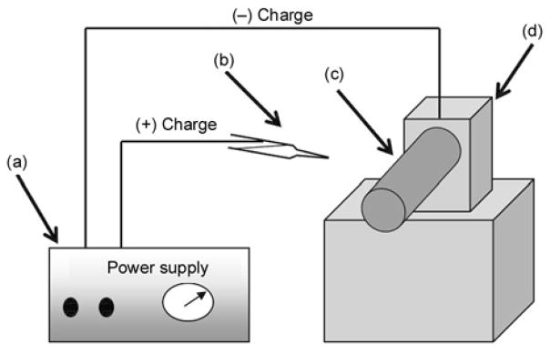
Schematic diagram of a simple electrospinning spinning apparatus: (a) dc power supply (b) Syringe (e) Rotating collector (d) Electric motor
2.4. In-vitro bioactivity test
To verify the advantage of incorporating HAp NPs in PU nanofibers, in-vitro bioactivity of both of pristine PU and PU/HAp nanofiber mats had been examined. Briefly, the in-vitro bioactivity study was performed using SBF solution, which was prepared by using the method described elsewhere [30]. The salt components, like NaCl, NaHCO3, KCl, K2HPO4, MgCl2 6H2O, HCl, CaCl2, Na2SO4, and (CH2OH)3CNH2, were added in the same proportions, as those described in the reference, so to give the final ionic concentration of human plasma. The pH of the ionic buffer was adjusted to 7.4 by adding 0.1 M HCl or 0.1 M NaOH. The nanofiber mats were soaked in SBF and were incubated at room temperature with a rotary shaker at a speed of 40 rpm. The SBF was replaced with a fresh one, for every 2 days for a total period of 10 days. Further on, to investigate the formation of the bone-like apatite on the nanofiber surfaces, samples were vacuum dried and observed under FE-SEM.
2.5. Characterization
The morphology of the nanofiber mats was analyzed with a field emission scanning electron microscope (FE-SEM) Hitachi S-7400, Japan with an operating voltage at 200 kV combined with the energy dispersive X-ray (EDS). Transmission electron microscopy (TEM) was performed with JEOL JEM 2010 operating at 200 kV, (JEOL Ltd., Japan) and was combined with the energy dispersive X-ray. Both the FE-SEM and TEM instruments, were obtained directly from the company located at branch offices in South Korea. Additionally, scanning electron microscope (SEM) (Leo 435 VP) obtained from Carl Zeiss SMT Ltd., equipped with EDS operating at accelerating voltage of 3 kV was also used. The Information about the phases and crystallinity was obtained using Rigaku X-ray diffractometer (XRD, Rigaku Co., Japan) with Cu Kα (λ = 1.54056 Å) radiation over Bragg angles ranging from 10 to 80°. The spectroscopic characterization was investigated with Fourier-transform infrared (FT-IR); the spectra were recorded by grinding samples with KBr pellets using a Varian FTS 1000 FT-IR, Mid-IR spectral range, cooled DTGS detector, and Scimitar series (Varian Inc., Australia). The thermal stability and influence upon incubation of nanofiber mats before and after incubation in SBF was carried out with a Pyris TGA (Perkin Elmer Co., USA) by heating from 50 to 800°C under a continuous oxygen purge of 20 ml/min. The heating rate was 20°C/min.
3. Results and discussion
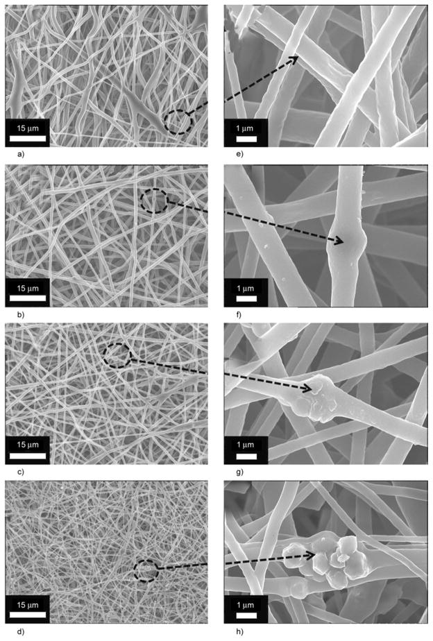
Electrospinning of colloidal solution that contains various amounts of HAp (0 to 7%) generated membranes that consist of well-defined nanofibers. As shown in Figure 2a and 2e, the FE-SEM images of nanofibers in low and high magnifications had been obtained after performing the electrospinning process. Figures 2a and 2e, obtained from electro-spinning pure PU solution, demonstrates that smooth, uniform and bead-free nanofibers were produced. It is clear from the high magnification micrograph, that smooth and continuous fibers are formed by pristine PU. Moreover, its counterparts, containing various amounts of HAp (i.e., 3, 5 and 7%) are presented in Figure 2b, 2c and 2d, respectively. The morphology of the polymer nanofibers (in terms of general nanofibrous morphology) has not been affected by the addition of HAp in these electro-spun mats. However, it can be observed that small decrease in diameter of nanofibers while analyzing Figures 2a, 2b, 2c and 2d. Furthermore, one can easily observe that the amount of HAp NPs increases as the concentration of HAp increases in the original colloidal solution used in electrospinning. In more details, the high magnification from the former figures are represented in Figures 2f, 2g and 2h. Actually, the observed NPs in (Figure 2f, 2g and 2h) are the large sized HAp particles; in other words, the particles with diameters larger than the average nanofiber diameter could not be embedded inside the nanofibers, and instead, they attach to the nanofiber threads or in simpler words they remain non-encapsulated. Moreover, the small sized NPs are encapsulated inside the nanofibers, analogously to the polymer/HAp in electrospun nanofiber mats that were previously reported [17–20].
Figure 2.
FE-SEM images for nanofibers that contain different amounts of HAp: 0% (a), 3% (b), 5% (c) and 7% (d) at low magnification. Corresponding figures containing 0% (e), 1% (f), 3% (g) and 7% (h) at high magnification from the encircled areas of low magnification images are also included.
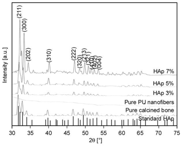
XRD is a highly trustable technique utilized to investigate the nature of any crystalline compounds. The XRD pattern of pure HAp and nanofiber mats is presented in Figure 3. In this figure, the vertical base lines represent the standard HAp according to the JCPDS data base [31, 32]. As shown in this figure, all the corresponding peaks originating from the base line (i.e., standard HAp) and synthesized HAp NPs generally match with each other, which satisfy that the produced HAp is purely crystalline. Strong diffraction peaks at 2θ values for HAp can be seen at 31.77, 32.90, 34.08, 40.45, 46.71, 48.62, 49.46, 51.28, 52.10 and 53.14° that correspond to the crystal planes (211), (300), (202), (310), (222), (320), (213), (410), (402) and (004) [31, 32]. Therefore, it can be concluded that the calcination processes have eliminated the other impurities from the bovine bones [29], and the obtained molecular skeleton consists of pure HAp. Further on, the spectra of the pure PU, which is also represented in this figure, because the PU is amorphous in nature, it can be observed that the spectra do not possess any such reasonable peak to indicate its non-crystalline nature. However, compared with its other modified counterparts obtained from electrospinning the HAp-containing colloids, the spectra possess reasonable peaks, which are located at the same diffraction angles, that of standard HAp peaks and the used HAp in these nanofibers. These findings confirm that nanofibers involve HAp NPs within them and simultaneously support the FE-SEM results. It is interesting to note, that the intensities of the peaks obtained from XRD analysis increased as the concentration of original HAp used in the colloidal solutions was increased.
Figure 3.
XRD results for the standard (the vertical base lines) and prepared hydroxyapatite (calcined). Also, the spectra of pristine PU and the prepared hydroxyapatite/PU nanofiber mat with different concentrations of hydroxyapatite.
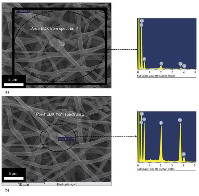
To ensure that the added HAp particles are really present in/on nanofibers, FE-SEM equipped with EDS analysis was utilized for one of the modified nanofibers containing HAp NPs; the results are presented in Figure 4. As shown in Figure 4a and its corresponding EDS data, originating from the area analyses of the nanofibers. The evident presence of Ca and P peaks, from the (area analyses) indicates the presence of HAp, from this marked area (Figure 4a). For point EDS, from a specific area, the results are shown in Figure 4b, and its corresponding EDS is also presented. From this figure, we can clearly find the increase in concentration of the Ca to P ratios compared to the area EDS (Figure 4a). The Ca to P ratio from both areas (one with swelled and whole area) was in the range of 1:50±10, which is more or less equal to natural HAp. The presence of HAp at this (specific area) indicates that this part is rich in HAp and additionally this discussion, clarifies the dilemma that these swelled areas are beads, which is an electrospinning defect. It is worth mentioning, that presence of beads can be favorable in certain applications, for instance to increase the superhydrophobicity of nanofiber mats. In particular, this type of finding was observed when nanofibers of poly(3-hydroxy-butyrate-co-3-hydroxyvalerate) (PHBV) was fabricated with various beads by electrospinning [33]. However, in our case we have obtained completely bead-free nanofibers which is favorable in general application of nanofibers, when nanofibers are to be used for implant purposes.
Figure 4.
FE-SEM equipped with EDS images from one of the nanofibers containing HAp NPs. Area EDS of the nanofiber mat from the encircled area and its corresponding EDS scan results (a). Point EDS of the nanofiber mat from the point area that contains HAp NP and its corresponding EDS scan results (b).
It is well known fact, that transmission electron microscope (TEM) analysis can be utilized to differentiate between crystalline and amorphous structures of materials. To investigate this phenomenon, the sampling was achieved by placing the TEM grid very close to the tip opening of the syringe needle for a few seconds during electrospinning process. In Figure 5 it can be observed that the nanofiber morphology is consistent with FE-SEM images in morphology. Figure 5a, also draws our attention to an interesting finding that the PU nanofibers can capture some large HAp NPs, which leads to more naked HAp NPs, which is beneficial in hard tissue applications. For further investigation, Figure 5b demonstrates the HR-TEM results for the black area; this image clearly shows apparent strips, which indicate high crystallinity for the marked area, considering the approved non-crystalline nature of the PU; this black area can be confidently attributed to HAp. The lattice image of an individual HAp from HR-TEM indicates that the HAp particle is an absolute crystal, with well-defined lattice fringes, and the lattice spacing of 0.47 nm, corresponds to the (110) HAp plane. The selected area electron diffraction (SAED) image in the (upper inset Figure 5b) reveals good crystallinity because there are no imperfections observed in the lattice planes. The atoms are arranged in a unique crystal lattice shape: the lattice shape of the standard HAp is hexagonal [31]. Moreover, the inverse Fast Fourier Transformation (FFT) of the (lower inset Figure 5b) image also confirms the good crystallinity in accordance with HR-TEM results.
Figure 5.
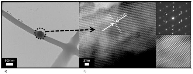
TEM of an individual nanofiber prepared from HAp/PU colloid (7 wt%): (a) high resolution transmission electron microscope (HR TEM) for the encircled area; (b) the (upper inset) selected area diffraction pattern (SAED) for the encircled area and the (lower inset) fast Fourier transformation (FFT) image
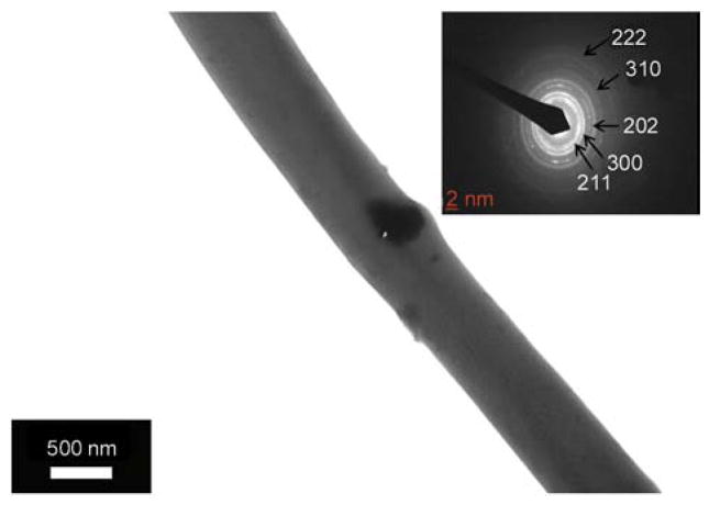
It is noteworthy to mention, that used HAp NPs in this study were of different diameters, however, the exact size of used HAp NPs used in these experiments was not fully studied. Knowing this fact, it was expected that small sized NPs will reside inside the nanofibers and large one will remain partially captured on nanofibers surfaces. As indicated in case of FE-SEM results, (Figure 1 and Figure 5) which successfully proved the presence of bead-free nanofibers in obtained nanofibers after blending with HAp NPs. The occurrence of bead-like structure was due to large sized HAp NPs which remain partially encapsulated inside nanofibers. In those results, the location and presence of small sized NPs, over the nanofibers could not be discussed at that point. In order to find out the occurrence of small sized NPs inside the nanofibers and simultaneously to abolish this dilemma, that some of the used NPs are really small in size and therefore, are encapsulated inside the nanofibers. In this context, Figure 6 shows a TEM micrograph of the PU nanofibers containing 7 wt% HAp (showing small sized Hap NPs). In this figure it can be observed that PU which is non-crystalline in nature appeared as white in color, while the highly crystalline HAp NPs looks darker in color. Also, from this figure, it can be clearly observed that small sized NPs are encapsulated inside the nanofibers, which abolish the dilemma that used NPs are large in size, which simultaneously support the finding that small sized NPs can be accommodated inside the nanofibers. The inset in Figure 6 shows the SAED ring pattern of the nanofiber with encapsulated HAp NP. There are no stacking faults observed in the lattice planes, which confirms the good crystallinity of the present NPs inside nanofibers. The d spacing at 8.14, 4.72, 4.07, 3.44 and 1.94 Å can be indexed to the (211), (300), (202), (310) and (222) planes, which are close to the XRD results.
Figure 6.
TEM of an individual nanofiber prepared from HAp/PU colloid (7 wt%), the inset figure shows selected area diffraction ring pattern from the edge of HAp NP
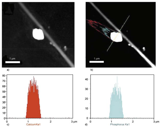
To check insightful understanding and chemical nature of NPs over nanofibers precisely, transmission electron microscopy (TEM) combined with the energy dispersive X-ray (EDS) analysis was done. For TEM-EDS analysis, the small nanofiber mats were ultrasonically dispersed in ethanol, and a drop of ethanol, which contained well dispersed nano-fibers, was placed on the TEM grid and examined under microscope. In this regard, Figure 7 shows a low-magnification TEM-EDS image of the nano-fiber from 7% PU/HAp nanofiber combination. From this image, it can be seen that the NPs are likely to be pulled away from main nanofiber stem because of the ultrasonication (Figures 7a and 7b). The EDS results from corresponding compound mapping results are shown in (Figures 7c and 7d). From these figures, one can clearly reveal the presence of Ca and P, which overall account the presence of HAp NPs. Therefore, these results strongly confirm the FE-SEM analyses that the naked NPs originate from HAp in the chemical composition present over the nanofibers.
Figure 7.
TEM-EDS image of nanofibers prepared from a HAp/PU colloid (7 wt%) (a); the linear EDS analysis along the line appearing in the figure (b); results of line mapping for two compounds analyzed as
 in
in
 (c) and
 in
in
 (d).
(d).
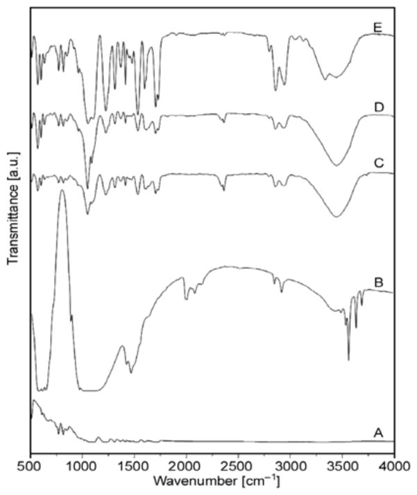
Figure 8 shows the FT-IR spectra of nanofibers derived after electrospinning colloidal solutions. Absorbance, resulting from vibrational modes from phosphates and hydroxyl groups is present in the spectra. For instance, the PO43− asymmetric stretching mode of vibration is characterized by a strong and complex band in the 1732–1037 cm−1 range and a medium intensity band at about 961 cm−1 that results from symmetric stretching vibrations [34]. The crystalline HAp generates characteristic OH bands at about 3446 cm−1, and this phenomenon is noted in all the nanofiber combinations containing HAp. The small peaks at 1700–1450 cm−1, indicate the existence of a Ca–O phase in the structure. A medium sharp peak at 628–635 cm−1, is assigned to the O–H bending deformation mode. The intensity of these peaks increases as the amount of original HAp used to make colloidal solution for electro-spinning increases.
Figure 8.
FT-IR spectra of pure PU nanofiber: (A) Calcined bones; (B) PU nanofiber containing 3% HAp; (C) PU nanofiber containing 5% HAp; and (D) PU nanofiber containing 7% HAp; (E)
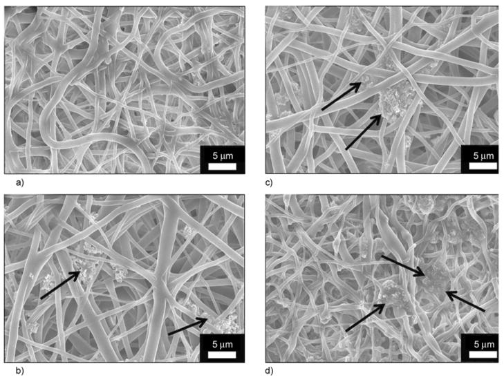
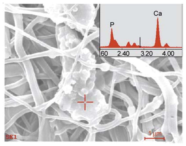
Generally, it is believed that the formation of apatite nuclei requires a seed to facilitate the formation of bone-like apatite. It worth mentioning, that the utilized SBF was previously exploited to precipitate biological apatite on proposed hard tissue materials [35, 36]. To prove these findings, the nanofibers were incubated in the presence of SBF, which resembles with the human physiological conditions (i.e., T = 37°C and pH = 7.4) for 10 days. During the incubation period, the SBF solution was refreshed every 2 days by refilling the new solution. After 10 days of incubation, the nanofiber mats were washed with triply distilled water to remove the associated SBF and dried in the presence of P2O5 in a vacuum dryer to remove the residual moisture associated from the incubation media. Thus, after the drying process, nanofiber mats were subjected to FE-SEM analysis; the results are shown in Figure 9. It can be concluded from Figure 9a that the pristine PU nanofibers cannot be utilized as hard tissue because no apatite-like materials were precipitated within 10 days of incubation. However, it can be deduced from Figures 9b, 9c and 9d that the structure, as indicated by arrows, incorporates HAp NPs in/on nanofibers and strongly activates precipitation of the HAp on the nanofibers mats. Moreover, to get the further confirmation about the induction of biological entities on the nanofibers, after the incubation in SBF, the EDS on apatite-like materials from one of nanofiber combination is presented in Figure 10. In this figure, and its point EDS graph from the indicated marked place, from this figure the presence of Ca and P peaks in the spectra can be clearly visualized. These findings clearly indicate the presence of induction of apatite-like materials at the specific indicated areas. This finding overall suggests utilizing the prepared PU/HAp mats for medical fields because both of PU and HAp are biologically safe. It is worth mentioning, that the rate at which the implant degradation occurs has to coincide, as much as possible with the rate of new bone formation. Considering that PU is biodegradable, and in a nanofibrous shape, which mimics the extra cellular matrix present in body, it will be an ideal site of cell seeding and basis for apatite proliferation in the initial step after the implant replacement.
Figure 9.
FE-SEM images for the PU nanofibers containing different amounts of hydroxyapatite: 0% (a), 3% (b), 5% (c) and 7% (d) with respect to polymer solution after incubation in SBF at 37°C for 10 days
Figure 10.
The EDS results from one of the modified nanofiber combination after incubation in SBF
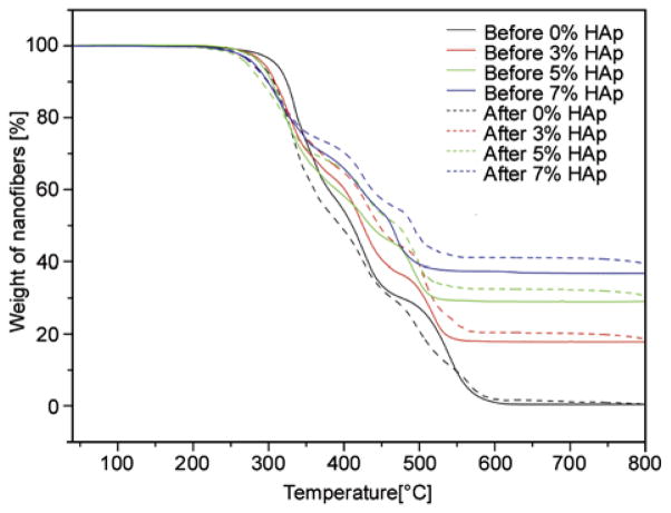
To get full confirmation that prepared nanofibers play a role in the formation of extra apatite upon incubation in SBF, and simultaneously support the FE-SEM and EDS results (i.e., Figure 9 and Figure 10). The TGA analyses of nanofibers for before and after incubation in SBF are represented in Figure 11. It was expected, that induction of biological apatite on nanofibers surfaces would result in increases of the residual weights during TGA analyses. Accordingly, from TGA analyses it was observed that the nanofibers before incubation in SBF show low residual weights remaining after exposure to a temperature of 550°C (marked by the complete lines). The nanofibers analyzed after incubation in SBF (marked by dashed lines) show higher residual weights remaining than the nanofibers used without incubation in SBF. It is interesting to note, that the residual weight of the nanofibers (i.e., 3, 5, and 7% HAp) that were incubated in SBF gained more residual weight compared with the pristine nano-fibers (i.e., 0% HAp). The presence of HAp in nano-fibers might motivate the apatite formation process during incubation in SBF. Furthermore, these results confidently affirms, the hypothesis of apatite induction on surfaces of nanofibers upon the presence of apatite nuclei and confidently supports the results shown in FE-SEM (Figure 9 and Figure 10).
Figure 11.
Thermal behavior and gain in residual weight of the PU nanofibers containing different amounts of hydroxyapatite before and after incubation in SBF at 37°C for 10 days
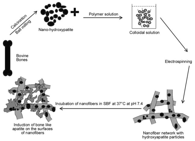
The whole procedure for making the ideal implants was described carefully. We introduce a generalized scheme to summarize the procedure and to justify that nanofibers bearing HAp NPs will act as favorable candidates for induction of apatite nuclei; therefore, they will be used as suitable candidates for future implant applications. Briefly, (Figure 12) indicates that the HAp NPs were obtained from calcination of bovine bones that were ground with a ball milling to obtain nanoparticulate size. Further step, involve the formation of the colloidal solution, which was electrospun to form nanofibers. These nanofibers containing HAp NPs were subjected to incubation in SBF. The presence of HAp around the nanofibers acted as seed, which promoted apatite particles to rest on the surfaces of nanofibers.
Figure 12.
The systematic presentation for this novel strategy
4. Conclusions
In conclusion, economically promising, environmentally desirable and biologically safe natural HAp NPs can be obtained from high temperature calcination of bovine bone. Electrospinning of a colloid solution comprised of the prepared HAp NPs and PU produces electrospun polymeric mats that include attached HAp NPs and partially captured NPs in the PU nanofibers. Nanofibrous shapes with a high structural space offer a bio-mimicking environment to accommodate and induce biological apatites on nanofiber surfaces. The HAp NPs alone strongly enhance the precipitation of biological apatites from the SBF solution during the incubation process because the NPs act as nuclei for the crystallization process. The SBF can be used to induce the formation of apatite on the nanofiber surfaces. The FE-SEM and TGA analyses can be utilized to differentiate the formation of excessive apatite on the surface of nanofibers upon incubation of SBF. In addition, the biological properties of both natural HAp and PU polymer and the results obtained in this study strongly suggest utilizing the proposed PU/HAp in hard tissue engineering applications.
Acknowledgments
This work was supported by a grant from the Korean Ministry of Education, Science and Technology (The Regional Core Research Program/Center for Healthcare Technology & Development, Chonbuk National University, Jeonju 561-756 Republic of Korea). Faheem A. Sheikh and Javier Macossay are thankful for the partial financial support for this work from NIH-NIGMS-NIA grant # 1SC2AG036825-01.
References
- 1.LeGeros RZ. Calcium phosphates in oral biology and medicine. Karger; Basel: 1991. [PubMed] [Google Scholar]
- 2.Joschek S, Nies B, Krotz R, Göpferich A. Chemical and physicochemical characterization of porous hydroxyapatite ceramics made of natural bone. Biomaterials. 2000;21:1645–1658. doi: 10.1016/S0142-9612(00)00036-3. [DOI] [PubMed] [Google Scholar]
- 3.Lü XY, Fan YB, Gu D, Cui W. Preparation and characterization of natural hydroxyapatite from animal hard tissues. Key Engineering Materials. 2007;342–343:213–342. DOI: 10.4028/ www.scientific.net/KEM.342-343.213. [Google Scholar]
- 4.Ozawa M, Suzuki S. Microstructural development of natural hydroxyapatite originated from fish-bone waste through heat treatment. Journal of the American Ceramic Society. 2002;85:1315–1317. doi: 10.1111/j.1151-2916.2002.tb00268.x. [DOI] [Google Scholar]
- 5.Chen I-W, Wang X-H. Sintering dense nanocrystalline ceramics without final-stage grain growth. Nature. 2000;404:168–171. doi: 10.1038/35004548. [DOI] [PubMed] [Google Scholar]
- 6.Hill CM, An YH, Kang QK, Hartsock LA, Gogolewski S, Gorna K. Osteogenesis of osteoblast seeded polyurethane-hydroxyapatite scaffolds in nude mice. Macromolecular Symposia. 2007;253:94–97. doi: 10.1002/masy.200750713. [DOI] [Google Scholar]
- 7.Liao S, Chan CK, Ramakrishna S. Stem cells and biomimetic materials strategies for tissue engineering. Materials Science and Engineering: C. 2008;28:1189–1202. doi: 10.1016/j.msec.2008.08.015. [DOI] [Google Scholar]
- 8.Sheikh FA, Barakat NAM, Kanjwal MA, Chaudhari AA, Jung I-H, Lee JH, Kim HY. Electrospun antimicrobial polyurethane nanofibers containing silver nanoparticles for biotechnological applications. Macromolecular Research. 2009;17:688–696. doi: 10.1007/BF03218929. [DOI] [Google Scholar]
- 9.Hong KH. Preparation and properties of electrospun poly(vinyl alcohol)/silver fiber web as wound dressings. Polymer Engineering and Science. 2006;47:43–49. doi: 10.1002/pen.20660. [DOI] [Google Scholar]
- 10.Sheikh FA, Barakat NAM, Kanjwal MA, Jeon S-H, Kang H-S, Kim H-Y. Self synthesize of silver nanoparticles in/on polyurethane nanofibers: Nano-biotechnological approach. Journal of Applied Polymer Science. 2010;115:3189–3198. doi: 10.1002/app.31418. [DOI] [Google Scholar]
- 11.Kim GH, Han H, Park JH, Kim WD. An applicable electrospinning process for fabricating a mechanically improved nanofiber mat. Polymer Engineering and Science. 2007;47:707–712. doi: 10.1002/pen.20744. [DOI] [Google Scholar]
- 12.Kidoaki S, Kwon IK, Matsuda T. Structural features and mechanical properties of in situ–bonded meshes of segmented polyurethane electrospun from mixed solvents. Journal of Biomedical Materials Research Part B: Applied Biomaterials. 2006;76:219–229. doi: 10.1002/jbm.b.30336. [DOI] [PubMed] [Google Scholar]
- 13.Khlystalova TK, Kurganova MN, Demina AI, Petova MB, Tarakanov OG. Hydrolytic stability of polyurethanes in model biological media. Mechanics of Composite Materials. 1986;21:763–767. doi: 10.1007/BF00605943. [DOI] [Google Scholar]
- 14.Han JH, Taylor JD, Kim DS, Kim YS, Kim YT, Cha GS, Nam H. Glucose biosensor with a hydrophilic polyurethane (HPU) blended with poly-vinyl alcohol/vinyl butyral copolymer (PVAB) outer membrane. Sensors and Actuators B: Chemical. 2007;123:384–390. doi: 10.1016/j.snb.2006.08.042. [DOI] [Google Scholar]
- 15.Hainš N, Friščić V, Gordoš D. Testing electrostatic properties of polyurethane coated textiles used for protective clothing. International Journal of Clothing Science and Technology. 2003;159:250–257. doi: 10.1108/09556220310478350. [DOI] [Google Scholar]
- 16.Khil M-S, Cha D-I, Kim H-Y, Kim I-S, Bhattarai N. Electrospun nanofibrous polyurethane membrane as wound dressing. Journal of Biomedical Materials Research Part B: Applied Biomaterials. 2003;67:675–679. doi: 10.1002/jbm.b.10058. [DOI] [PubMed] [Google Scholar]
- 17.Nie H, Wang C-H. Fabrication and characterization of PLGA/HAp composite scaffolds for delivery of BMP-2 plasmid DNA. Journal of Controlled Release. 2007;120:111–121. doi: 10.1016/j.jconrel.2007.03.018. [DOI] [PubMed] [Google Scholar]
- 18.Kim H-W, Knowles JC, Kim H-E. Hydroxyapatite/poly(%-caprolactone) composite coatings on hydroxyapatite porous bone scaffold for drug delivery. Bio-materials. 2004;25:1279–1287. doi: 10.1016/j.biomaterials.2003.07.003. [DOI] [PubMed] [Google Scholar]
- 19.Venugopal J, Low S, Choon AT, Sampath Kumar TS, Ramakrishna S. Mineralization of osteoblasts with electrospun collagen/hydroxyapatite nanofibers. Journal of Materials Science: Materials in Medicine. 2008;19:2039–2046. doi: 10.1007/s10856-007-3289-x. [DOI] [PubMed] [Google Scholar]
- 20.Zhang Y, Venugopal JR, El-Turki A, Ramakrishna S, Su B, Lim CT. Electrospun biomimetic nanocomposite nanofibers of hydroxyapatite/chitosan for bone tissue engineering. Biomaterials. 2008;29:4314–4322. doi: 10.1016/j.biomaterials.2008.07.038. [DOI] [PubMed] [Google Scholar]
- 21.Zhou S, Zheng X, Yu X, Wang J, Weng J, Li X, Feng B, Yin M. Hydrogen bonding interaction of poly(D,L-lactide)/hydroxyapatite nanocomposites. Chemistry of Materials. 2007;19:247–253. doi: 10.1021/cm0619398. [DOI] [Google Scholar]
- 22.Zheng X, Zhou S, Li X, Weng J. Shape memory properties of poly(D,L-lactide)/hydroxyapatite composites. Biomaterials. 2006;27:4288–4295. doi: 10.1016/j.biomaterials.2006.03.043. [DOI] [PubMed] [Google Scholar]
- 23.Kim H-W, Song J-H, Kim H-E. Nanofiber generation of gelatin–hydroxyapatite biomimetics for guided tissue regeneration. Advanced Functional Materials. 2005;15:1988–1994. doi: 10.1002/adfm.200500116. [DOI] [Google Scholar]
- 24.Fujihara K, Kotaki M, Ramakrishna S. Guided bone regeneration membrane made of polycaprolactone/calcium carbonate composite nano-fibers. Biomaterials. 2005;26:4139–4147. doi: 10.1016/j.biomaterials.2004.09.014. [DOI] [PubMed] [Google Scholar]
- 25.Erisken C, Kalyon DM, Wang H. Functionally graded electrospun polycaprolactone and &-tricalcium phosphate nanocomposites for tissue engineering applications. Biomaterials. 2008;29:4065–4073. doi: 10.1016/j.biomaterials.2008.06.022. [DOI] [PubMed] [Google Scholar]
- 26.Sui G, Yang X, Mei F, Hu X, Chen G, Deng X, Ryu S. Poly-L-lactic acid/hydroxyapatite hybrid membrane for bone tissue regeneration. Journal of Biomedical Materials Research Part A. 2007;82:445–454. doi: 10.1002/jbm.a.31166. [DOI] [PubMed] [Google Scholar]
- 27.Barakat NAM, Khalil KA, Sheikh FA, Omran AM, Gaihre B, Khil SM, Kim HY. Physiochemical characterizations of hydroxyapatite extracted from bovine bones by three different methods: Extraction of biologically desirable HAp. Materials Science and Engineering: C. 2008;28:1381–1387. doi: 10.1016/j.msec.2008.03.003. [DOI] [Google Scholar]
- 28.Barakat NAM, Khil MS, Omran AM, Sheikh FA, Kim HY. Extraction of pure natural hydroxyapatite from the bovine bones bio waste by three different methods. Journal of Materials Processing Technology. 2009;209:3408–3415. doi: 10.1016/j.jmatprotec.2008.07.040. [DOI] [Google Scholar]
- 29.Aerssens J, Boonen S, Lowet G, Dequeker J. Inter-species differences in bone composition, density, and quality: Potential implications for in vivo bone research. Endocrinology. 1982;139:663–670. doi: 10.1210/en.139.2.663. [DOI] [PubMed] [Google Scholar]
- 30.Kokubo T, Kushitani H, Sakka S, Kitsugi T, Yamamuro T. Solutions able to reproduce in vivo surface-structure changes in bioactive glass-ceramic A-W3. Journal of Biomedical Materials Research. 1990;24:721–734. doi: 10.1002/jbm.820240607. [DOI] [PubMed] [Google Scholar]
- 31.Leng Y, Qu S. TEM examination of single crystal hydroxyapatite diffraction. Journal of Materials Science Letters. 2002;21:829–830. doi: 10.1023/A:1015722607608. [DOI] [Google Scholar]
- 32.Lopatin CM, Pizziconi V, Alford TL, Laursen T. Hydroxyapatite powders and thin films prepared by a sol-gel technique. Thin Solid Films. 1998;326:227–232. doi: 10.1016/S0040-6090(98)00531-8. [DOI] [Google Scholar]
- 33.Yoon YI, Moon HS, Lyoo WS, Lee TS, Park WH. Superhydrophobicity of PHBV fibrous surface with bead-on-string structure. Journal of Colloid and Interface Science. 2008;320:91–95. doi: 10.1016/j.jcis.2008.01.029. [DOI] [PubMed] [Google Scholar]
- 34.Blakeslee KC, Condrate RA. Vibrational spectra of hydrothermally prepared hydroxyapatites. Journal of the American Ceramic Society. 1971;54:559–563. doi: 10.1111/j.1151-2916.1971.tb12207.x. [DOI] [Google Scholar]
- 35.Oyane A, Uchid M, Choong C, Triffitt J, Jones J, Ito A. Simple surface modification of poly(%-caprolactone) for apatite deposition from simulated body fluid. Biomaterials. 2005;26:2407–2413. doi: 10.1016/j.biomaterials.2004.07.048. [DOI] [PubMed] [Google Scholar]
- 36.Lin K, Chang J, Cheng R. In vitro hydroxyapatite forming ability and dissolution of tobermorite nano-fibers. Acta Biomaterialia. 2007;3:271–276. doi: 10.1016/j.actbio.2006.11.003. [DOI] [PubMed] [Google Scholar]


