Abstract
This paper presents a new actuation scheme for in-plane bidirectional translation of polysilicon microelectrodes. The new Chevron-peg actuation scheme uses microelectromechanical systems (MEMS) based electrothermal microactuators to move microelectrodes for brain implant applications. The design changes were motivated by specific needs identified by the in vivo testing of an earlier generation of MEMS microelectrodes that were actuated by the Chevron-latch type of mechanism. The microelectrodes actuated by the Chevron-peg mechanism discussed here show improved performance in the following key areas: higher force generation capability (111 μN per heat strip compared to 50 μN), reduced power consumption (91 mW compared to 360 mW), and reliable performance with consistent forward and backward movements of microelectrodes. Failure analysis of the Chevron-latch and the Chevron-peg type of actuation schemes showed that the latter is more robust to wear over four million cycles of operation. The parameters for the activation waveforms for Chevron-peg actuators were optimized using statistical analysis. Waveforms with a 1-ms time period and a 1-Hz frequency of operation showed minimal error between the expected and the actual movement of the microelectrodes. The new generation of Chevron-peg actuators and microelectrodes are therefore expected to enhance the longevity and performance of implanted microelectrodes in the brain. [2011-0341]
Keywords: Biomedical devices, BioMEMS, brain–machine interface, electrothermal microactuators, in vivo microelectrodes, neural prosthesis, robots
I. INTRODUCTION
SEVERAL microelectromechanical systems (MEMS) microactuators have been designed and developed for biological applications [1]-[5]. Detailed reviews of a range of MEMS microactuators used for micro- and nanoscale manipulations and their capabilities in terms of maximum force, displacement, resolution, and frequency can be found in earlier reports [6], [7]. MEMS microactuators with the appropriate design specifications can therefore be chosen based on the requirements of an application. For instance, a polymer V-shaped electrothermal microactuator array was fabricated to measure the mechanical compliance of cell in biological media [8]. Kim et al. [9] have demonstrated single cell manipulation using electrothermally activated microgripper with force resolution in the nanonewton range. These examples demonstrate the potential of electrothermal microactuators for precise positioning and manipulation in biological applications. However, several challenges exist in the design, development, and performance characterization of these actuators so that they perform with a high degree of repeatability, accuracy, and reliability [10]-[16]. The demands on the microactuator performance are quite varied, depending on the specific biological application in question. For instance, long-term implantable applications are significantly more challenging both for the microactuators and the packaging than short-term implantable applications; applications involving cell cultures are typically more controllable than applications involving implantation in vivo. This paper focuses on microactuators specifically designed and developed for brain prosthetic applications in which the microactuators were used to move microelectrodes and monitor electrical activity of single neurons in the brain of awake behaving animals. The aforementioned application demands that such MEMS devices perform reliably over the lifetime of a patient, typically 70 years [17]. The longevity of current microelectrode implants in the brain is highly variable [18], [19], and there is significant degradation in neural signal quality after a few weeks of implantation [20], [21]. Most current microelectrode arrays are fixed, with no capability to reposition them once implanted. Movable microelectrodes in combination with automatic closed-loop controls [22] are a powerful technology that gives the ability to position the microelectrode automatically, provide good quality signal-to-noise ratios [1], and improve the yield of neuronal units recorded per microelectrode [23] potentially extending the lifetime of microelectrode implants. Earlier reports have consistently demonstrated an improved performance using motorized movable microelectrodes for neuronal recording applications in the brain [23]-[32]. However, the aforementioned technologies to move microelectrodes do not readily allow for scaling up the number of microelectrodes to record from ensembles of neurons in the brain, which is often a requirement in brain monitoring applications. Surface micromachining of MEMS [33] enables the creation of complex microscale movable systems that can be batch fabricated using high throughput standard MEMS fabrication processes. Over the past ten years, the authors have developed, in collaboration with Sandia National Laboratories, novel MEMS-based movable microelectrode arrays fabricated using the SUMMiT-V process [1], [3], [4]. It is a unique technology that gives the ability to precisely position the microelectrode array after implantation while maintaining comparable chip size and weight as that of the conventional microelectrodes.
The most recent MEMS electrothermal actuators were developed to translate the microelectrode using a Chevron-latch type of mechanism [3]. These devices were successfully implanted in rodents and were able to record neural signal activity for over 13 weeks. The aforementioned study revealed some important design requirements for the MEMS movable microelectrodes for successful operation in long-term experiments in the brain. Microelectrode movement consistently led to a significant improvement in the quality of the neuronal signal during the first three weeks after implantation. However, after three weeks, in 5 out of 11 cases, microelectrode movement did not lead to significant improvement in the quality of the signal recorded [1]. It was suspected that the most likely reason for this degradation in performance was that the microactuators were not effective in moving the microelectrodes past the glial sheath (a fibrous tissue encapsulation) [34], [35] that typically begins to envelop the implants beyond three weeks. Consequently, microactuators with greater force capabilities than the current microactuators are expected to be more effective in moving past the glial sheath. Furthermore, implants in the previous study [1] using Chevron-latch electrothermal microactuators contained bulky moving structures like the release locks and the V-shaped central drive shuttle. The drive actuators that moved the microelectrode and the actuators that controlled the release mechanism were overlaid in two different polysilicon layers of the five-layer SUMMiT-V process, separated only by 2 μm. As a result, their mechanical structures were complex with potential for failure in the long term. One of the eight MEMS devices in the previous study that were actuated after implantation in rodents experienced structural failures at multiple places. Thus, a new actuation mechanism where complex mechanical structures were not overlaid on top of each other was desirable to reduce the likelihood for failure in long-term experiments with awake behaving animals. It is also preferable for a biomedical implant to have minimal power requirements to minimize the number of battery recharges. Thus, the chronic experiments with Chevron-latch-microactuator-based movable microelectrodes indicated the need for a newer actuation mechanism that can generate higher forces, have less complex mechanical structures, and consume less power.
In addition, the distance moved by the microelectrode after several actuation cycles needs to be predictable in order to accurately determine the location of the implanted microelectrode in the brain at any given time. This is important as the microactuators are further incorporated in a closed-loop control to automate the actuation of the microelectrode implant in the brain [22], [30] for autonomous prosthetic systems. For a MEMS-based system, the microactuator operating parameters (such as voltage levels, frequency of pulses, and time period of activation) directly impact the dynamics of microelectrode movement. Given the inertial and frictional forces inherent in the design of these MEMS devices, different operating parameters can lead to varying degrees of accuracy in the microelectrode displacement. Therefore, an optimization exercise [36] is done in the current study to analyze the movement of the microelectrode and determine the optimal parameter set required to operate the microactuator for minimal error in microelectrode displacement.
Finally, factors like mechanical wear, fracture/fatigue, humidity of the environment, etc., can cause considerable change in the material properties which affects the function of MEMS devices [37]-[39]. Prior studies have reported on the reliability of MEMS electrothermal chevron actuators fabricated using the SUMMiT-V process [40]-[42]. In this paper, we report and compare the lifetime analysis of the MEMS devices (the earlier Chevron-latch microactuators and the new Chevron-peg microactuators) using resistance measurements across the electrothermal microactuators while in operation. Scanning electron microscope (SEM) analysis of both MEMS devices after four million actuation cycles was done to assess failure mechanisms.
II. METHODS
The MEMS devices reported here were 3 mm × 7 mm chips that accommodate three microelectrodes capable of bidirectional (forward and backward) movement as shown in Fig. 1. Each microelectrode is a polysilicon shank, which is 50 μm wide, 4 μm thick, and 5 mm long. There were four electrothermal microactuators coupled with each microelectrode that operate and control its movement. Spring-type leads make the electrical connection between the moving microelectrode and the stationary bond pad.
Fig. 1.
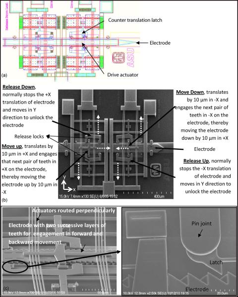
(a) Computer-aided design (CAD) diagram of the microelectrode actuated by the Chevron-latch type of actuation mechanism. (b) SEM image of a microelectrode actuated by Chevron-latch mechanism. The microelectrode is capable of bidirectional movement, and a pair of disengage actuators activates the “release down” actuator that frees the microelectrode which is moved down by the “move down” actuator. The microelectrode moves up by a similar mechanism. The broken arrows indicate the direction of displacement of the actuators. (c) SEM image of the Chevron-latch mechanism showing the complex structures of dual countertranslation latches and an overlying layer of bulky drive actuators. Enlarged portion shows two rows of teeth (pointing in opposite directions) realized on successive layers of polysilicon constituting the microelectrode to allow bidirectional movement and the point of contact between the latch and the microelectrode.
In both of the MEMS technologies (the Chevron-latch microactuator and the Chevron-peg microactuator) reported here, the microelectrodes were moved using electrothermal actuation. The electrothermal actuators were in-plane “Chevron” type of actuators. Chevron or bent-beam actuators are used extensively in high force applications and are popular in integrated sensor–actuator MEMS devices [43]. The basic structure consists of a V-shaped beam anchored at the two ends and connected to a central shuttle at its apex. When an electric current is passed through the beam, it expands due to Joule heating and pushes the apex forward. The displacement is dependent on the length of the beams and the angle of orientation. The force generated at the central shuttle is linearly related to the displacement. An important advantage of this type of actuator is that an array of beams when attached to a single central shuttle can cause a linear increase in the force output.
A. Chevron-Latch Actuation
The earlier generation of MEMS microelectrode array was actuated by a Chevron-latch mechanism and is illustrated in Fig. 1. A detailed description of this actuation mechanism was provided in an earlier report [3]. Briefly, there were four disengage actuators that activate the “release up” and “release down” locks, respectively. The locks hold the microelectrode in position in the inactive state and release the microelectrode for movement during the active state. The microelectrode has two rows of teeth on successive layers of polysilicon constituting the microelectrode, to which the locks latch onto. The microelectrode was moved stepwise by the “move down” and “move up” actuators moving it in the forward and the backward direction, respectively. The electrothermal heat strips of the “release” actuators and the “move” actuators were fabricated in two different polysilicon layers and placed one above the other, and they intersected perpendicularly.
Overall, each microelectrode was coupled to six microactuators, and the failure of even one microactuator can lead to failure in microelectrode movement. The release latches were large structures tethered to the polysilicon beams at hinge joints (refer to Fig. 1) and hence were susceptible for failure at these joints. Structurally, the design had multiple overlying mechanical microstructures as shown in Fig. 1(c) which impact the overall reliability and functioning of the device in the long term.
B. Chevron-Peg Actuation
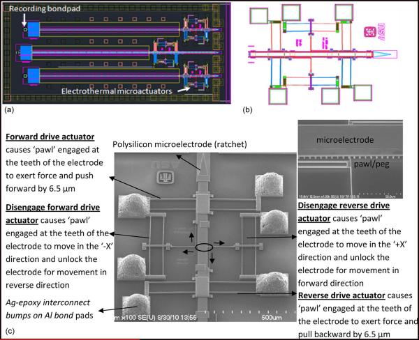
The current generation of MEMS microelectrode array reported here for the first time was actuated by a Chevron-peg-type mechanism that attempts to address some of the shortcomings of the earlier Chevron-type actuators identified by long-term in vivo testing [1]. The microelectrode has a linear array of teeth spaced 6.5 μm apart at the edges. The “pawl,” a peglike structure, engages the teeth of the microelectrode and locks it in position, preventing displacement in rest conditions. The new actuators have a simplified movement mechanism with only one “pawl” that engages with the microelectrode teeth as shown in the inset in Fig. 2(c). A SEM of the drive system with the four microactuators and the microelectrodes are shown in Fig. 2(c). It has two pairs of electrothermal Chevron actuators that perform identical function. The “forward drive” actuator and “disengage forward drive” actuator control the forward movement of the microelectrode, and the “reverse drive” and “disengage reverse drive” actuators control the backward movement of the microelectrode. The central shuttle of the drive and disengage actuators are both connected in an L-shape arrangement to a “pawl” that engages the microelectrode. A set of timed pulse waveforms were applied to these actuators to operate the pawl and move the linear ratchet/microelectrode in a given direction.
Fig. 2.
(a) CAD diagram of the new generation of MEMS microelectrode device with an array of three microelectrodes actuated by Chevron-peg microactuators. The microelectrodes are electrically connected to the recording bond pad via spring type leads. (b) CAD diagram showing an enlarged image of the microelectrode actuated by the Chevron-peg type of actuation mechanism with a pair of disengage and drive actuators placed opposed to each other. (c) SEM image of microelectrode actuated by Chevron-peg type of actuation. The microelectrode has maximum displacement of 5 mm in steps of about 6.5 μm. The inset shows the encircled region which is the contact between the pawl/peg and a single row of teeth on the microelectrode.
C. Design of Waveforms for Activating the Chevron-Peg Microactuators
The transient response of the electrothermal actuators to a step of voltage is modeled and is shown that the actuator takes finite time to reach steady-state displacement [13]. The time taken by the actuator to reach the steady-state displacement is called its “thermal time constant.” This time constant is based on the actuator design, length of the beams, polysilicon resistivity and thermal conductivity, gap size to the substrate, air gap conduction, etc. The activation waveforms for the microactuators are therefore designed such that, each time a voltage is turned on or off for an actuator, there is a delay time that is at least equal to the thermal time constant (labeled “t” in Fig. 3 and henceforth referred to as a “time period”) before the next voltage is applied to activate any of the other microactuators. This “time period” ensures that the actuator reaches thermal equilibrium and is fully extended or fully retracted due to a change in voltage.
Fig. 3.
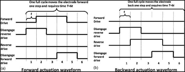
Activation waveforms for the four different electrothermal actuators to move the microelectrode. The amplitude of the waveform depends on the operating voltage defined for the particular actuator. The microelectrode moves by one step, i.e., 6.5 μm in one complete actuation cycle. The time taken for one complete actuation cycle to achieve one forward or one backward step is six time periods or “6t.” (a) Forward actuation waveform. (b) Backward actuation waveform.
D. Forward Movement of the Microelectrode
The movement of the microelectrode toward the external environment that is off the edge of the die was referred to as “forward” movement. Fig. 3(a) shows the timing of the waveform for actuating the microelectrode in the forward direction. The waveform was split into six time periods that constitute a full cycle of operation. The position of the actuators at the beginning of each time period is illustrated in Fig. 4. At the beginning of time period t = 1, a step voltage was applied to the “disengage reverse” actuator that retracts the pawl from the microelectrode. It takes one time period for the actuator to fully retract. At the beginning of t = 2, the second step voltage was applied to the “forward drive” actuator, and it was displaced proportional to the applied voltage. The pawl attached to the central shuttle of the actuator caused the microelectrode to move forward in the direction of the actuator displacement. Furthermore, at the beginning of t = 3, the “disengage reverse” actuator began to cool down, and the pawl tethered to the next teeth on the microelectrode. The pawl attached to the “disengage forward” actuator was angled and still anchored to the microelectrode. At t = 4, a pulse was applied to the “disengage forward” actuator to release the pawl, and after period t = 5, the actuator cooled down to reanchor at the next teeth. Thus, in one full actuation cycle, the microelectrode moved one step which is a distance equal to 6.5 μm.
Fig. 4.
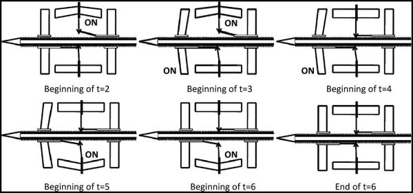
Illustration showing the microactuator positions in a Chevron-peg type of actuation mechanism where each panel corresponds to individual time periods in one full actuation cycle waveform. Refer to Fig. 3 for the sequence of voltages applied during the respective time period in the actuation waveform. At the end of the cycle, the pawl ratchets over one tooth of the microelectrode, moving it forward by one step.
E. Optimal Parameters for Actuation Waveform
Retracting the microelectrode toward the die was referred to as the “reverse” movement. The waveforms for reverse movement were symmetrical to those of the forward movement and follow the same sequence of operation as shown in Fig. 3(b). A critical difference is that the forward motion was achieved with the actuator operating in hot condition, and the reverse motion was achieved with the actuator operating in cold condition. The reverse drive actuator was placed opposed to the forward drive actuator, and hence, the pawl pulled on the microelectrode as the actuator cooled down. At any point of time in the actuation cycle, there was always one peg anchoring the microelectrode and keeping the spring leads in tension.
F. Optimal Parameters for the Waveform
Operating Voltage
Operating voltages for the actuators were determined experimentally. The voltage applied is proportional to the displacement of the actuators and is also proportional to the force output. On the drive actuators, the voltage applied should be sufficient to move the peg to the next tooth location. On the disengage actuators, it should be sufficient to fully retract the peg from the teeth in order to allow for the free movement of the microelectrode. There is a lower threshold voltage level, below which the actuator shows no displacement. Voltages were stepped up from 4 V in increments of 0.5 V until optimal displacements for both kinds of actuators were observed. Observations of peg location and actuator displacements were made using a video recording setup described hereinafter. Voltages above a maximum upper threshold value can cause the actuators to melt. Operating the actuators close to the upper threshold voltage can accelerate the failure of the device and increase chances for wear-out and failure. Hence, the actuation voltages were determined based on an optimal voltage level between the lower and upper thresholds of operation.
Operating Frequency and Time Period
The operating frequency of the actuator depends on the time constant of the actuator. When a voltage is applied across the actuator, it reaches a state of thermal equilibrium where the heat loss from the actuator equals the heat generation and the actuator will be at its steady-state displacement. Typically, it takes 0.5–1 ms to heat up and about 0.7–1 ms to cool down. Hence, a conservative estimate of the time constant was taken as t = 1 ms, so the period for a full cycle was T = 6 ms with an operating frequency of 167 Hz. At a time constant of t = 0.5 ms, a full cycle operation would take 3 ms. Hence, 333 Hz can be the upper bound for the operating frequency of this design. However, for the purpose of actuating the microelectrodes in the brain, much lower operating speeds are adequate and arguably even desired. Once the actuator reaches steady-state displacement at 1 ms after activation, holding the voltage levels high will have no effect on the actuator displacement, and it will remain at steady state.
The microelectrode can be operated at different speeds in the following ways: 1) Increase the time period “t” for which a voltage is applied to the actuator. Here, the microelectrode operates slowly as the same actuation cycle would take longer time to execute. Movement efficiency is tested with an increase in time period to t = 10 ms that results in full actuation cycle operation time of T = 60 ms. The increased period of operation could possibly play a role in overcoming stiction issues. 2) The actuation waveforms can be applied at different pulse repetition rates (referred to as “frequencies” here and in the rest of this paper). In this case, although one full actuation cycle takes the same amount of time to complete, i.e., 6*t where t is the time period, the delay between consecutive actuation cycles is varied. The movement efficiency of the microelectrode is tested for frequencies of 0.1 Hz (1 actuation cycle/10 s), 1 Hz (1 actuation cycle/s), and 10 Hz (10 actuation cycles/s), which includes the range of speeds required for successful penetration of the brain tissue after the removal of the outer dura mater layer. At these operating frequencies, the microelectrode is expected to move 6.5 μm every 10 s, 6.5 μm every second, or 65 μm every second, respectively.
Reliability in Movement of the Microelectrode
In order to optimize the operating parameters for the activating waveforms, a design of experiment analysis was done. A general full factorial design was used with frequency, time period, and direction of movement as the main factors. Frequency has three continuous levels of operation, 0.1 Hz (slow), 1 Hz (medium), and 10 Hz (fast), and time period has two levels of operation—1 ms (fast) and 10 ms (slow). It is also necessary to characterize the movement of the microelectrode when it moves forward versus when it moves backward. Thus, the third factor would be the direction of movement with two discrete values—the forward and the backward movement. The experiment is run with three replicates for each set of factor levels. Replication helps in estimating internally the errors due to high-order interactions among factors that usually occur while conducting an experiment. There were two response variables for the experiment: 1) the mean error between the expected movement of the microelectrode and the actual movement as measured by the optical setup (described hereinafter) and 2) the standard deviation of the error that gives us an estimate of how variable the error is in a given run.
A design test matrix for the three full factorial design experiments with three replicates was determined. Design Expert 8.0.5 was used to determine the run orders and the design matrix for the experiment. The experiment has a randomized test sequence.
G. Experimental Setup
The die was tested in an electrical test bench. The probes in the test bench were placed on the bond pads of the actuators as shown in Fig. 2(b). TTL pulses from the computer generated by Tucker Davis Technologies’ signal processing interface (TDT technologies, Boca Raton, FL) were fed into a custom drive signal generation circuit as shown in the schematic in Fig. 5. This circuitry allowed the manipulation of voltage, pulsewidth, and frequency of the drive signals as required. The pulse waveforms were applied in sequence to each of the probes in the test bench.
Fig. 5.
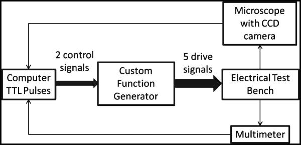
Schematic of experimental setup for characterization of movement of microelectrode.
Optical Setup for Measuring Microelectrode Displacement
A custom characterization setup was built to observe the movement of the microelectrodes under different actuation schemes described earlier. A setup with an optical microscope of 120x magnification and a c-mount adapter for a digital camera was used for characterizing the movement of the microelectrodes on a probe station. The movement of the microelectrodes was recorded as a video sequence with a frame rate of 3 fps. Upon completion of the runs in the experimental design, videos characterizing the movement of the microelectrodes were obtained. The frames in the captured video were analyzed using a custom image processing algorithm in MATLAB that measured the displacement of the microelectrode between consecutive frames. A series of data points that show the displacement profile of the microelectrode with time is created. The error between the distance moved by the microelectrode as measured by the optical setup and the expected movement of the microelectrode due to the given operating parameter set was examined. The expected waveform was calculated from the frequency of actuation. For example, at 1 Hz, the microelectrode is expected to move 6.5 μm every second. An error series was calculated for each run and was defined by the following equation. The mean and standard deviation of this error series for each run were determined
Force Measurements
Force measurements were made using a flip chip packaged MEMS device secured to the tower of a stereotactic frame. The device was then lowered by using a 5-DOF micromanipulator. A load cell (Wipotec, Germany, model: MTC 10/30–ZER) was used to make the force measurements. It has a maximum weighing range of 2 g (maximum force range of 20 mN) and has a sensitivity of 0.1 mg (i.e., sensitivity to force of 1 μN). The MEMS chip was positioned above the load cell in the vertical direction such that the edge of the MEMS package was at a distance of about 2 mm from the load cell surface. The microelectrodes were extended off the edge of the die by approximately 1 mm. The microelectrode tip and the load cell surface were visualized under a stereo-zoom microscope with a digital camera connected to a display screen. The microelectrode was actuated with operating voltages as determined earlier until the tip of the microelectrode pushed on the load cell surface. The load cell was connected to the computer via a serial port, and force measurements were made once every 1 μs.
Resistance Measurements to Test Long-Term Electrical Functionality and Mechanical Wear
The actuators were operated over four million cycles of actuation at 10 actuation cycles/s. The voltage was set at the operating voltage level at which the actuators are normally operated which is the safe zone of operation, lower than the level at which they undergo plastic deformations. The current through the actuator under displacement was measured using a digital multimeter (M3510A, Picotest Corporation, Taiwan) connected to the computer via a serial port. Resistance measurements were made at randomized intervals of time during the four million cycles. The duration of every measurement lasted for half an hour during which a reading was recorded every 25 ms. Thereby, the resistance of the actuators was sampled during steady-state displacement and zero displacement.
Failure Analysis of Microactuators
The SEMs of the MEMS device were analyzed for any structural changes or failures, presence of debris, oxidation, etc. After four million cycles of operation, the actuator strips were imaged to determine mechanical wear and physical deformations that would disrupt the actuation mechanism.
III. RESULTS
The Chevron-peg actuators required lower voltages (5.8–6.5 V) and have finer displacement resolution (6.5 μm) compared to the earlier Chevron-latch electrothermal microactuators which required 9–10 V and had a displacement resolution of 9 μm. The average voltage during one cycle of actuation for the Chevron-peg microactuator is calculated as follows: V* duty cycle for each of the three waveforms. The time period of actuation is taken as 1 ms, and hence, 6.5 V * 2 ms/6 ms is for the disengage waveforms, and 7 V * 3 ms/6 ms is for the forward actuation waveform [refer to Fig. 3(a)]. The resistance values for the disengage actuators are approximately 295 Ω, and the forward/reverse actuators are approximately 210 Ω. Therefore, the power consumption is 16 mW/cycle to actuate the disengage actuators and 58 mW/cycle for the forward/reverse actuation. Hence, the total power consumption in the Chevron-peg type of actuator is 90 mW/cycle. The Chevron-latch type of device has two waveforms for actuation with duty cycles of 100% and 33%. Therefore, the average voltage for the two waveforms in one cycle of actuation is 9 V and 9 V * 1/3. The corresponding resistances for the latch actuators and for the forward drive actuator are approximately 230 and 300 Ω. Therefore, the total power consumption is 380 mW/cycle, with 350 mW required to release both locks and 30 mW to move the microelectrode forward in one actuation cycle. Hence, the new device with the Chevron-peg type of actuation has 76% lesser power consumption than the older generation of Chevron-latch type of actuation.
A. Optimal Parameters for the New Actuation Scheme
Operating Voltage
The Chevron-peg actuator required approximately 5.8 V and 10 mA dc to fully disengage the pawl from the microelectrode. The forward drive actuator required approximately 6.5 V and 12 mA to ratchet over one peg slot, resulting in a linear displacement of 6.5 μm per actuation. The reverse drive actuator required 7 V to move back one step. The differences in voltage requirement was because the reverse drive actuator exerted force when it was cooling down, and hence, the force applied on the microelectrode returned to zero as the actuator returned to the zero displacement position. The upper threshold voltage for disengage and drive actuators was 10 V. This was found by increasing the activation voltage until the heat strips of the actuators burned out. Hence, activation voltages in the range of 6–7 V were well within the upper threshold decreasing the chances for wear-out and failure.
B. Optimal Frequency and Time Period of Activation Waveforms
Design Expert provided statistical models that captured the effect of three factors: 1) frequency of the activation waveform; 2) time period of the activation waveform; and 3) direction of microelectrode movement and their respective interactions on the two response variables—a) mean and b) standard deviation of error in the movement of the microelectrode. The mean and standard deviation values for each run followed a normal distribution as identified by the normal probability plot of the studentized residuals as shown in Fig. 6. Statistical analysis using analysis of variance (ANOVA) was done from the factors that most significantly affect the two response variables. In the ANOVA table generated by Design Expert, the interaction term of frequency and time period had significant impact on the mean error response with a p-value of 0.0003. Thus, frequency or time period factors individually do not influence the error rates significantly. In the ANOVA model for standard deviation response, only the direction of movement factor had significant impact with a p-value of 0.0331.
Fig. 6.
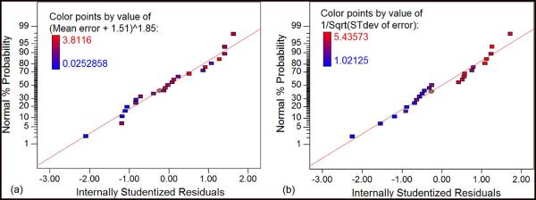
Normal probability plot of studentized residuals for (a) mean error responses and (b) standard deviation responses shows that the residuals satisfy the normality assumption for the model generated by ANOVA. All the responses should fall in a line and satisfy the “fat pencil test.”
The model output graphs showed the effect of the significant factors on the model response variables. In Fig. 7, the mean error response is minimal and is approximately zero for a frequency of 1 Hz and a time period of 1 ms. The expected and the actual waveforms for the aforementioned parameters of operation completely overlapped in both the forward and the backward direction of movement as shown in Fig. 8. The second model graph in Fig. 7(b) shows the standard deviation of the errors in various runs as a function of the direction of movement of the microelectrode. The standard deviation of error response while the microelectrode is moving forward had lower variation when compared to the same while the microelectrode is moving backward. This was consistent with the observation that the forward movement of the microelectrode was more uniform while the backward movement of the microelectrode resulted in skips and jumps that make the error variations large.
Fig. 7.
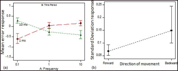
Model output graphs after ANOVA showing the effect of the most significant factors on the two response variables (a) mean error and (b) standard deviation of error. (A) Interaction graph shows the mean error for different combinations of frequency and time period as tested in the experimental design. The frequency of 1 Hz and 1 ms has the least mean error. (B) Only the direction of movement significantly affects the standard deviation where backward movement has larger standard deviation whereas forward movement is more consistent, with smaller standard deviation in errors.
Fig. 8.
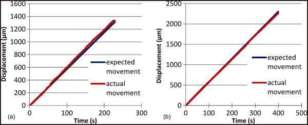
(a) Forward movement profile of an microelectrode actuated at 1-Hz frequency with 1-ms time period. (b) Backward movement profile of an microelectrode actuated by the same waveform parameters. In both cases, the expected and the actual movement profiles track each other closely.
The expected and actual movement profiles of an microelectrode actuated at 0.1 Hz with a 10-ms time period is shown in Fig. 9(a) that illustrates the skipping behavior observed in backward movement. In this case, the microelectrode skipped a few actuation cycles at approximately 500 s while the microelectrode was stuck. Repetition of the actuation waveforms allowed it to overcome the stiction at that position, and it again began moving backward. Fig. 9(b) shows the backward movement profiles of an microelectrode where the microelectrode jumped more than one peg per actuation, resulting in larger displacement than expected. The kind of movement profiles shown in Fig. 9 where the expected and the actual movement significantly differed from each other was observed in about one out of every five trials conducted.
Fig. 9.
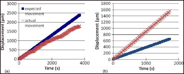
(a) Backward movement profile of an microelectrode actuated at 0.1 Hz with a time period of 10 ms. At 0.1 Hz, the microelectrode is expected to move by 6.5 μm every 10 s. The microelectrode got stuck after being displaced by about 200 μm, and repeated pulsing of the actuators allows it to recover movement. (b) Backward movement profile of an microelectrode actuated at 0.1 Hz with a waveform of 1 ms. The microelectrode jumps through more than one step per actuation cycle, resulting in a faster retraction of the microelectrode than expected.
C. Force Output
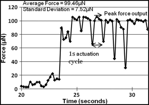
The force generated by the Chevron-latch microactuator on one microelectrode is shown in Fig. 10. The peaks and troughs correspond to each actuation cycle. The peak force is generated when the release locks are activated and the forward microactuator moves the microelectrode down. The trough in the force data corresponds to the instant when the release locks hold the microelectrode in position before the beginning of the next actuation cycle. As shown in Fig. 10, the average peak force generated by the MEMS microelectrode is approximately 99.5 ± 7.5 μN. The MEMS devices used in the earlier chronic in vivo study [1] had microactuators with four thermal strips, and they generated a force of approximately 200 μN since the force scales linearly with the number of thermal strips on the actuator.
Fig. 10.
Force output by Chevron-latch microactuators with two heat strips on the polysilicon microelectrode.
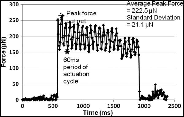
The force generated by the Chevron-peg type of actuator on a microelectrode is shown in Fig. 11. The actuators have two thermal strips as shown in Fig. 2. As the microelectrode is actuated, a peak force of 250 μN is registered when the drive actuator moves the microelectrode down by one step and the microelectrode tip touches the load cell. Each actuation cycle is for 60 ms as the time period t = 10 ms, and the waveforms for actuation are as shown in Fig. 3. The force output varies in accordance with the actuation cycle, and the peak is recorded every time the microactuator moves the microelectrode. At the end of the actuation cycle, the microelectrode is held in position by the disengage microactuators and exerting a resting force of approximately 150 μN corresponding to the microelectrode being pressed against the load cell in the new position. After the initial 12 actuation cycles, the microelectrode has already moved approximately 80 μm, and a marginal decrease in the peak output force is observed as a result of buckling in the microelectrodes.
Fig. 11.
Force output by Chevron-peg microactuators with two heat strips. Peak force output occurs at the instance the microactuator displaces the microelectrode during the actuation cycle. The microelectrode is actuated over 20 actuation cycles and the average peak force output is calculated.
D. Resistance Measurements for Lifetime Analysis
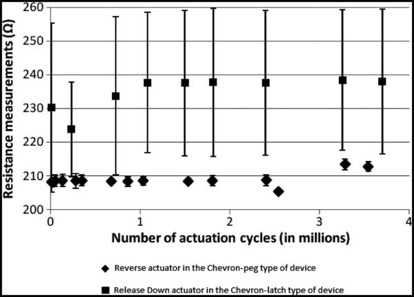
Electrical resistance measurements were made over four million cycles of operation of the microactuator. Resistance across the reverse drive actuator in the Chevron-peg-type device (n = 3) and release down actuator in the Chevron-latch-type device (n = 6) were measured while the actuators were in operation. They were operated at 6.5 and 9 V, respectively. The mean and standard deviation of all the resistance values were calculated and plotted as shown in Fig. 12 for n = 1 devices in both cases. The results for all samples were typical of the results shown here. The Chevron-peg-type actuator showed fairly constant resistance across four million cycles of operation as evidenced by the smaller error bars in Fig. 12. The Chevron-latch actuator showed deviations in resistance across four million cycles of operation with large variations across individual readings.
Fig. 12.
Resistance measurements across the reverse actuator in the Chevron-peg type and release down actuators in the Chevron-latch type that were operated at a frequency of 10 actuation cycles/s. The reverse actuator of the Chevron-peg type shows constancy in electrical measurements. The release down actuator in the Chevron-latch type shows large variations in individual measurements that were recorded over a period of 1 h while the actuator was in operation.
E. Failure Analysis in Microactuators
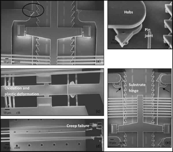
The Chevron-peg type of actuator remained functional even after four million cycles of operation. No structural deformations were observed after four million cycles of operation. The Chevron-latch actuator failed to operate beyond four million cycles of actuation. A SEM analysis was done to determine the reasons for failure. SEM micrographs documenting the different mechanisms of failure in these MEMS devices are shown in Fig. 13. Mechanical wear was the dominant failure mode as seen here. Pin joints, substrate hinges/tether points, and hubs were critical points of failure as observed in Fig. 13(a). Failure by fracture due to fatigue was a dominant failure mode largely due to the tethering of the release lock (a large mechanical structure) by a thin beam which induces large stresses and results in fatigue and wears at the joint over 4 × 10⁶ continuous actuation cycles. An enlarged view of the broken hinge can be seen in Fig. 13(b). Fig. 13(c) and (d) shows failure in the electrothermal strips of the microactuators. Oxidation and plastic deformation of the beams can be observed in the beams on the left-hand side of Fig. 13(c). The electrothermal strips on the right-hand side have melted. In Fig. 13(d), mechanical failure in the electrothermal strips has occurred due to creep, and there is ductile separation. Fig. 13(e) illustrates deformation in the beam that orients the release lock with the teeth of the microelectrode, as a result of which the teeth and locking structure are misaligned. Each of the aforementioned failure modes can be catastrophic to the operation of the device.
Fig. 13.
SEM micrographs showing the different failure modes in Chevron-latch type of device after four million cycles of operation. (a) Fracture at a hinge joint due to fatigue. (b) Magnified view of the fatigue failure in the region highlighted in A. (c) Illustration of oxidation and plastic deformation in the electrothermal strips of the actuator. (d) Creep and plastic deformation in the electrothermal actuator beams due to large stresses as they operate the large V-shaped pawl in the move down actuator. (e) Plastic deformation in the beam that orients the release-lock structure and the teeth of the microelectrode leading to misalignment that hinders the movement mechanism of the microelectrode.
IV. DISCUSSION
In the new devices with Chevron-peg microactuators, the microelectrodes have a single set of teeth along the length on either side (compared to two successive layers of teeth on each side of the microelectrode in the Chevron-latch actuators) that results in more reliable grasping of the microelectrode by the actuators. Furthermore, overlying thermal strips were eliminated and have significantly reduced the polysilicon surface areas that come in contact during actuation. The bulky dual countertranslation latches that were prone to fatigue failure in the earlier actuation mechanism are replaced by a simple pinlike design in the new actuation mechanism. Therefore, the new generation of microactuators and microelectrodes is expected to be less prone to mechanical failure in the long term.
The current generation of devices with the Chevron-peg actuators is a low-power design with lower supply voltages that is preferable for long-term implantable applications. Table I summarizes the design improvements in the Chevron-peg type of actuation mechanism.
TABLE I.
COMPARISON BETWEEN THE TWO TYPES OF ACTUATION MECHANISMS
| Device attributes | Chevron-latch mechanism | Chevron-peg mechanism |
|---|---|---|
| Voltage levels for actuation | 9V | 5.8-6.5 V |
| Actuation step | 9 μm | 6.5 μm |
| Full stroke length | 5 mm | 5 mm |
| Maximum frequency of operation |
333 Hz | 333 Hz |
| Minimum duration of activation cycle |
3 ms | 6 ms |
| Power consumption | 380 mW/cycle | 90 mW/cycle |
| Force generated per heat strip | 50 μN | 111 μN |
The Chevron-peg type of actuation produces force per heat strip that is twice as large as that of the previous Chevron-latch type of design with almost 30% decrease in the voltage levels applied for actuation. The actuators in the Chevron-latch type and the new Chevron-peg type are both of the Chevron style bent-beam thermal actuators. The output force of a Chevron style thermal actuator increases with the increase in the width and thickness of the thermal strip [48]. The actuators in the Chevron-latch design have a rectangular cross section with dimensions of 2.25 μm (thickness) and 2.2 μm (width). While the actuators in the Chevron-peg type of actuator have two rectangular cross-sectional dimensions of 2.25 μm (thickness) and 5 μm (width) each with an intermediate V-shaped cross section of 2 μm (thickness) and 2 μm (width). This increase in the cross-sectional area of the Chevron-peg type of actuator is the reason for the increase in force output.
The average force output increases linearly with the number of actuator legs. The new MEMS devices have three Chevronpeg actuators as shown in Fig. 2, where the left and the right microelectrodes have drive actuators with five heat strips each and the middle microelectrode has microactuators with ten heat strips. Thus, these devices are capable of generating a maximum force output of approximately 550 μN (on the left and right microelectrodes) and 1 mN (on the middle microelectrode), respectively. We have determined that the force required to penetrate an ex vivo brain using polysilicon microelectrode moved at 10 μm/s was about 200 μN (unpublished data). However, the forces required to penetrate the glial sheath in long-term implantation are unknown and can only be estimated from acute measurements in the brain [34], [44], [45]. Force output in the current generation of devices has increased by approximately three times on the left and right microelectrodes and five times on the middle microelectrode. The increased force is expected to enable movement in the brain for a longer duration of time.
The results from experiments to optimize the operating parameters of the activation waveforms in the Chevron-peg microactuators indicate that frequency or time period alone does not influence the error between the actual and expected microelectrode displacement profiles. It is the interaction of these two factors that determines the error values. In about 2/3 of the runs to test microelectrode displacement, the error values are within the 30% range. During the forward movement of the microelectrode, the error values increase to approximately 30% error during the initial phase as the microelectrodes just begin to move, before settling down to a steady-state value. This steady-state error value is the cumulative error from the previous cycles. Inertial and static frictional forces appear to play a significant role in determining microelectrode displacement errors during the initial phase when the microelectrodes are about to move as shown in Fig. 14. However, once the microelectrode is in motion, there appears to be no further errors in displacement as indicated by the steady-state values for the cumulative errors. This is in contrast to variations in the error seen when the microelectrode is moving backward. Although the range of error percentages is comparable to the range seen during forward movement, the standard deviation of error is large for the runs when the microelectrode is moving backward. This is also verified by the statistical model where the standard deviation of error is only influenced by the direction of movement of the microelectrode and is seemingly unaffected by the frequency or time period of the activation waveforms or their interaction. The large variations during the backward movement of the microelectrode can be attributed to the slipping issues discussed earlier. However, the slipping issues are more prominent as the microelectrode gets retracted further into the chip. This is probably because of the reduction in the spring force (that acts in the direction of the backward movement of the microelectrode) as the spring attached to the microelectrode begins to relax while the microelectrode is drawn into the chip, and the resistive forces due to friction become more dominant. The displacement error when the microelectrode is extended far out from the edge of the die is less variable.
Fig. 14.
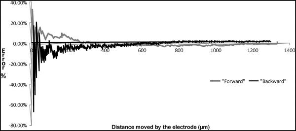
Microelectrode displacement errors as function of distance moved. The microelectrode was actuated with the following parameters: Pulsewidth of 1 ms and frequency of movement of 1 Hz. Significant error is seen during the initial phase of movement, and the error settles down to a steady-state value after approximately 360 μm (55 cycles of movement).
The following reason can also potentially contribute to the slipping seen during backward microelectrode movement. In the current design, the reverse actuator pulls the microelectrode back while cooling down. As the actuator cools down, it pulls back to its zero displacement position. Consequently, the actuator exerts force with a receding profile that diminishes to zero as the actuator reaches its zero displacement position. Therefore, in the presence of frictional forces, the actuator may not fully reach its zero displacement position. This can result in slipping as the actuator does not pull back far enough to ratchet over the next tooth and the microelectrode will not move at all.
In order to overcome slippage during backward movement, the reverse actuator could be operated at a higher voltage such that it extends out more than one peg each time and the actuator would have at least crossed one peg when resistive forces are present. Another way to avoid slippage during backward movement would be to operate the reverse actuator also in the hot condition similar to the forward actuator. However, this option is less desirable. There is approximately 20-MPa residual stresses in the polysilicon due to the fabrication process [46]. Packaging will add to the stresses in the die as well. Any stress in the actuator beams will cause the thermal actuators to have some small nonzero displacement even when unpowered. This might result in the reverse actuators and forward actuators becoming misaligned with respect to the pegs on the microelectrode, resulting in the failure of the MEMS device. Thus, arranging the actuators as in the current scheme, with one operating hot and the other cool, fixes this problem and causes the actuators to be insensitive to stress issues. An additional advantage of the symmetric placement of actuators is that it allows the device to function even when one of the drive actuator fails. When either one of the forward or reverse actuators fails, the waveforms for the disengage actuators can be switched, and the functional actuator can be made to operate in the hot or cold condition, thus moving the microelectrode forward or backward.
Slipping issues during the backward movement of microelectrode were also observed in the Chevron-latch mechanism during actuation experiments on the electrical test bench. In this design, the microelectrode has two rows of teeth oriented in opposite directions. The forward lock holds the microelectrode at the top layer while the backward lock holds the microelectrode at the bottom layer of teeth as shown in Fig. 1(c) and (d). Small misalignments on the order of 2–3 μm could cause the latch to interlock in the wrong position and jam the microelectrode. This was observed in both the forward and the backward movement of the microelectrode. Repeated pulsing of the actuators could create enough force to move the microelectrode again. Also, the spring attached to the microelectrode could often exert enough force during backward movement to pull the microelectrode back more than the expected number of steps. The design was improved with a peg interlock that holds the microelectrode in place by opposing a single layer of teeth in the Chevron-peg type of actuation mechanism to prevent any such vulnerability to misalignment. However, these movement irregularities were not observed when the microelectrode was implanted, as the friction between the microelectrode and the brain tissue prevented misalignments and the spring force was not sufficient to pull back the microelectrode.
The electrical resistance measurements were sampled as the actuator was in the dynamic state of transition, from steady-state displacement to zero displacement in the actuation cycle. The actuator resistance increases significantly with heating (because resistivity of polysilicon is a strong function of temperature), and the variations seen during individual measurements may be attributed to this. However, both the Chevron-peg and the Chevron-latch actuators were sampled at various points of the heating and cooling cycle. The lower variations in resistance in the linear-ratcheting actuators could be due to better heat dissipation. Changing resistance implies change in the material properties of the legs of the actuator and mechanical deformations that affect its electrical functionality. The large variations in resistance measurements in the Chevron-latch microactuators could be due to two causes: 1) The actuators are coupled to bulky release locks that could cause excessive strain and material degradation during displacement, and 2) a higher voltage is applied for actuation, and the legs of the actuator are shorter, so the heat generation is more and the area available for heat dissipation is less. The SEM images of the Chevron-latch type of microactuators after four million cycles of actuation indicate wear in the actuator thermal strips, fracture at hinge joints, and creep failure. It is known that creep rate in polysilicon increases as temperature increases [47]. The higher heat dissipation in the Chevron-latch actuator can further accelerate plastic deformation. The resistance of the actuator beams in the Chevron-peg-type actuator is lower than that in the Chevron-latch-type actuator which lowers heat dissipation and thus decreases the possibility of failure due to creep. After four million cycles of operation, the Chevron-peg actuator was still functional.
The mechanism for fracture due to wear is described by van Spengen [39]. Polysilicon in air is always covered by a thin native oxide layer. A small crack can develop on the surface of this oxide layer which propagates by stress corrosion cracking mechanism. When the externally applied stress is large enough, crack growth is observed leading to the oxidation of deeper polysilicon layers. This could be the possible mechanism of failure in Fig. 13(a). In the Chevron-peg type of actuator, such joints where there is high concentration of stresses are eliminated by constructing a simple pinlike structure that tethers to the microelectrode.
V. CONCLUSION
We report here a new Chevron-peg microactuator that performs better than the Chevron-latch microactuator for potential implantable long-term brain prosthetic applications. The optimal operating parameters for activating the Chevron-peg actuators were first determined through an exhaustive set of experiments with different operating parameters and subsequent statistical analysis. The optimal parameter set for the activation waveforms to move the microelectrode forward and backward was determined. The new MEMS devices with Chevron-peg microactuators generate twice as much force per heat strip compared to that with the Chevron-latch microactuator, appear to be mechanically robust due partly to less complexity in their mechanical structure, consume less power, and have finer movement resolution. Lifetime analysis using resistance measurements and SEM analysis after four million cycles indicate that the Chevron-peg microactuators may be less prone to failure than the earlier Chevron-latch microactuators. We therefore conclude that the MEMS movable microelectrodes with Chevron-peg microactuators are likely to perform better than that with the Chevron-latch microactuators in long-term brain implant applications.
ACKNOWLEDGMENT
The authors would like to thank the Center for Solid State Electronic Research for the use of their clean-room facilities.
This work was supported by the National Institutes of Health under Grants R01NS055312 and R01NS055312-S1. Sandia National Laboratories is a multiprogram laboratory managed and operated by Sandia Corporation, a wholly owned subsidiary of Lockheed Martin Corporation, for the U.S. Department of Energy’s National Nuclear Security Administration under contract DE-AC04-94AL85000. Subject Editor D.-I. Cho.
Biographies

Sindhu Anand received the B.E.(Hons.) degree in electrical engineering and the M.Sc.(Hons.) degree in biological sciences from the Birla Institute of Technology and Science, Pilani, India, in 2008, and the M.S degree in biomedical engineering from Arizona State University, Tempe, in 2011, where she is currently working toward the Ph.D. degree in biomedical engineering, specializing in the neuroengineering track.
Her research interests include the development of robotic implantable technologies, design of neural interfaces, and BioMEMS.

Jemmy Sutanto (M’06) received the B.S. and M.S. degrees in mechanical engineering from the RMIT University, Melbourne, Australia, and the Ph.D. degree in mechanical engineering from the Georgia Institute of Technology, Atlanta.
He was a Senior Packaging Engineer with Intel Corporation with expertise in the high-density first-level interconnects for high-end CPUs. He was then an Associate Research Scientist with the School of Biological and Health Systems Engineering, Arizona State University, Tempe. He is currently with Amkor Technology, Chandler, AZ, as a Program Manager for fine-pitch (< 40 μm) Cu pillar, chip on chip (CoC), and chip on wafer (CoW) technologies. He has been the author or coauthor of 16 journal papers and one book chapter. He is the holder of one U.S. patent, two trade secrets, and five patents pending. His research experience is in the areas of MEMS, bio-MEMS, and microelectronics/MEMS packaging.
Dr. Sutanto is a member of the American Society of Mechanical Engineers and the Biomedical Engineering Society.

Michael S. Baker received the B.S. and M.S. degrees in mechanical engineering from Brigham Young University, Provo, UT, in 1999 and 2002, respectively.
His research efforts were in the area of onchip actuation of MEMS bistable mechanisms. He is currently a Principle Member of the Technical Staff in the Advanced MEMS Department at Sandia National Laboratories, Albuquerque, NM. His research interests in MEMS include compliant mechanism design, acceleration switches, relays, and methods of actuation.

Murat Okandan (M’95) received the Ph.D. degree from The Pennsylvania State University, University Park.
He has been with Sandia National Laboratories, Albuquerque, NM, since 1999. He is a Principal Member of the Technical Staff at Sandia National Laboratories and has been involved in microelectronics and microsystems with expertise in solid-state device physics, microelectronics processing, and sensors. He has been contributing to and leads several projects ranging from biomedical to extreme environment/highly sensitive physical sensors (shock sensors for energetic materials, atomic magnetometers, microseismometers, and gravimeters) and microsystems-enabled renewable energy (MEPV), all leveraging the unique capabilities provided by microsystems. He has authored or coauthored over 30 publications, is the holder of 14 patents, and has nine patents pending and numerous invention disclosures.

Jit Muthuswamy (S’91–M’98–SM’08) received the M.S degree in electrical engineering and the M.S and Ph.D. degrees in biomedical engineering from Rensselaer Polytechnic Institute, Troy, NY.
He is currently an Associate Professor in Bioengineering in the School of Biological and Health Systems Engineering and an Affiliate Faculty in Electrical Engineering at Arizona State University, Tempe, AZ. His research program in developing novel neural interfaces has been supported by the National Institutes of Health, Whitaker Foundation, Defense Advanced Research Projects Agency, and the Arizona Biomedical Research Commission. His research interests are in neural engineering, neural interfaces, and BioMEMS.
Dr. Muthuswamy is a member of the Society for Neuroscience. He was the recipient of the Excellence in Neural Engineering Award at the Joint International Conference of the IEEE Engineering and Medicine Society and Biomedical Engineering Society in 2002 and the Outstanding Paper Award (along with coauthor and student, Nathan Jackson) at the the 41st Annual International Microelectronics and Packaging Society Symposium in 2008.
REFERENCES
- 1.Jackson N, Sridharan A, Anand S, Baker M, Okandan M, Muthuswamy J. Long-term neural recordings using MEMS based move-able microelectrodes in the brain. Frontier Neuroeng. 2010 Jun 18;3(10):1–13. doi: 10.3389/fneng.2010.00010. [DOI] [PMC free article] [PubMed] [Google Scholar]
- 2.Mukundan V, Pruitt BL. MEMS electrostatic actuation in conducting biological media. J. Microelectromech. Syst. 2009 Apr;18(2):405–413. doi: 10.1109/JMEMS.2009.2013398. [DOI] [PMC free article] [PubMed] [Google Scholar]
- 3.Muthuswamy J, Okandan M, Gilletti A, Baker MS, Jain T. An array of microactuated microelectrodes for monitoring single-neuronal activity in rodents. IEEE Trans. Biomed. Eng. 2005 Aug;52(8):1470–1477. doi: 10.1109/TBME.2005.851478. [DOI] [PMC free article] [PubMed] [Google Scholar]
- 4.Muthuswamy J, Okandan M, Jain T, Gilletti A. Electrostatic microactuators for precise positioning of neural microelectrodes. IEEE Trans. Biomed. Eng. 2005 Oct;52(10):1748–1755. doi: 10.1109/TBME.2005.855712. [DOI] [PMC free article] [PubMed] [Google Scholar]
- 5.Receveur RAM, Lindemans FW, de Rooij NF. Microsystem technologies for implantable applications. J. Micromech. Microeng. 2007 May;17(5):R50–R80. [Google Scholar]
- 6.Bell DJ, Lu TJ, Fleck NA, Spearing SM. MEMS actuators and sensors: Observations on their performance and selection for purpose. J. Micromech. Microeng. 2005 Jul;15(7):S153–S164. [Google Scholar]
- 7.Sahu B, Taylor CR, Leang KK. Emerging challenges of microactuators for nanoscale positioning, assembly, and manipulation. J. Manuf. Sci. Eng. 2010 Jun;132(3):030917-1–030917-16. [Google Scholar]
- 8.Zhang WY, Gnerlich M, Paly JJ, Sun YH, Jing GS, Voloshin A, Tatic-Lucic S. A polymer V-shaped electrothermal actuator array for biological applications. J. Micromech. Microeng. 2008 Jul;18(7):075020-1–075020-8. [Google Scholar]
- 9.Kim K, Liu XY, Zhang Y, Sun Y. Nanonewton force-controlled manipulation of biological cells using a monolithic MEMS microgripper with two-axis force feedback. J. Micromech. Microeng. 2008 May;18(5):055013-1–055013-8. [Google Scholar]
- 10.Baker MS, Epp DS, Serrano JR, Gorby AD, Phinney LM. Sandia Na. Lab.; Albuquerque, NM: Thermomechanical measurements on thermal microactuators. SAND2009-0521. [Online]. Available: http:// www.osti.gov/bridge/servlets/purl/976937-eEp4ov/ [Google Scholar]
- 11.Cheng CH, Chan CK, Cheng TC, Hsu CW, Lai GJ. Modeling, fabrication and performance test of an electro-thermal microactuator. Sens. Actuators A, Phys. 2008 May 16;143(2):360–369. [Google Scholar]
- 12.de Boer MP, Luck DL, Ashurst WR, Maboudian R, Corwin AD, Walraven JA, Redmond JM. High-performance surface-micromachined inchworm actuator. J. Microelectromech. Syst. 2004 Feb;13(1):63–74. [Google Scholar]
- 13.Geisberger AA, Sarkar N, Ellis M, Skidmore GD. Electrothermal properties and modeling of polysilicon microthermal actuators. J. Microelectromech. Syst. 2003 Aug;12(4):513–523. [Google Scholar]
- 14.McLain TW, Lott CD, Harb JN, Howell LL. Modeling the thermal behavior of a surface-micromachined linear-displacement thermomechanical microactuator. Sens. Actuators A, Phys. 2002 Sep 30;101(1/2):239–250. [Google Scholar]
- 15.Olney A. Evolving MEMS qualification requirements. Proc. IEEE Int. Rel. Phys. Symp. 2010:224–230. [Google Scholar]
- 16.Park JS, Chu LL, Oliver AD, Gianchandani YB. Bent-beam electrothermal actuators—Part II: Linear and rotary microengines. J. Microelectromech. Syst. 2001 Jun;10(2):255–262. [Google Scholar]
- 17.Kruger J, Caruana F, Volta RD, Rizzolatti G. Seven years of recording from monkey cortex with a chronically implanted multiple microelectrode. Frontier Neuroeng. 2010;3(6):1–9. doi: 10.3389/fneng.2010.00006. [DOI] [PMC free article] [PubMed] [Google Scholar]
- 18.Chestek CA, Gilja V, Nuyujukian P, Foster JD, Fan JM, Kaufman MT, Churchland MM, Rivera-Alvidrez Z, Cunningham JP, Ryu SI, Shenoy KV. Long-term stability of neural prosthetic control signals from silicon cortical arrays in rhesus macaque motor cortex. J. Neural Eng. 2011 Aug;8(4):045005-1–045005-11. doi: 10.1088/1741-2560/8/4/045005. [DOI] [PMC free article] [PubMed] [Google Scholar]
- 19.Nicolelis MAL, Dimitrov D, Carmena JM, Crist R, Lehew G, Kralik JD, Wise SP. Chronic, multisite, multielectrode recordings in macaque monkeys. Proc. Nat. Acad. Sci. 2003 Sep 16;100(19):11 041–11 046. doi: 10.1073/pnas.1934665100. [DOI] [PMC free article] [PubMed] [Google Scholar]
- 20.Kipke DR, Vetter RJ, Williams JC, Hetke JF, Nunamaker EA. Chronic neural recording using silicon-substrate microelectrode arrays implanted in cerebral cortex. IEEE Trans. Biomed. Eng. 2004 Jun;51(6):896–904. doi: 10.1109/TBME.2004.826680. [DOI] [PubMed] [Google Scholar]
- 21.Suner S, Fellows MR, Vargas-Irwin C, Nakata GK, Donoghue JP. Reliability of signals from a chronically implanted, silicon-based electrode array in non-human primate primary motor cortex. IEEE Trans. Neural Syst. Rehabil. Eng. 2005 Dec;13(4):524–541. doi: 10.1109/TNSRE.2005.857687. [DOI] [PubMed] [Google Scholar]
- 22.Cham JG, Branchaud EA, Nenadic Z, Greger B, Andersen RA, Burdick JW. Semi-chronic motorized microdrive and control algorithm for autonomously isolating and maintaining optimal extracellular action potentials. J. Neurophysiol. 2005 Jan;93(1):570–579. doi: 10.1152/jn.00369.2004. [DOI] [PubMed] [Google Scholar]
- 23.Fee MS, Leonardo A. Miniature motorized microdrive and commutator system for chronic neural recording in small animals. J. Neurosci. Methods. 2001 Dec 15;112(2):83–94. doi: 10.1016/s0165-0270(01)00426-5. [DOI] [PubMed] [Google Scholar]
- 24.Battaglia FP, Kalenscher T, Cabral H, Winkel J, Bos J, Manuputy R, van Lieshout T, Pinkse F, Beukers H, Pennartz C. The Lantern: An ultra-light micro-drive for multi-tetrode recordings in mice and other small animals. J. Neurosci. Methods. 2009 Apr 15;178(2):291–300. doi: 10.1016/j.jneumeth.2008.12.024. [DOI] [PubMed] [Google Scholar]
- 25.Eliades SJ, Wang X. Chronic multi-electrode neural recording in free-roaming monkeys. J. Neurosci. Methods. 2008 Jul 30;172(2):201–214. doi: 10.1016/j.jneumeth.2008.04.029. [DOI] [PMC free article] [PubMed] [Google Scholar]
- 26.Gray CM, Goodell B, Lear A. Multichannel micromanipula-tor and chamber system for recording multineuronal activity in alert, non-human primates. J. Neurophysiol. 2007 Jul;98(1):527–536. doi: 10.1152/jn.00259.2007. [DOI] [PubMed] [Google Scholar]
- 27.Haiss F, Butovas S, Schwarz C. A miniaturized chronic microelectrode drive for awake behaving head restrained mice and rats. J. Neurosci. Methods. 2010 Mar 15;187(1):67–72. doi: 10.1016/j.jneumeth.2009.12.015. [DOI] [PubMed] [Google Scholar]
- 28.Jackson A, Fetz EE. Compact movable microwire array for long-term chronic unit recording in cerebral cortex of primates. J. Neurophysiol. 2007 Nov;98(5):3109–3118. doi: 10.1152/jn.00569.2007. [DOI] [PubMed] [Google Scholar]
- 29.Venkateswaran R, Boldt C, Parthasarathy J, Ziaie B, Erdman AG, Redish AD. A motorized microdrive for recording of neural ensembles in awake behaving rats. J. Biomech. Eng. 2005 Nov;127(6):1035–1040. doi: 10.1115/1.2049332. [DOI] [PubMed] [Google Scholar]
- 30.Wolf MT, Cham JG, Branchaud EA, Mulliken GH, Burdick JW, Andersen RA. A robotic neural interface for autonomous positioning of extracellular recording electrodes. Int. J. Robot. Res. 2009;28(9):1240–1256. [Google Scholar]
- 31.Yamamoto J, Wilson MA. Large-scale chronically implantable precision motorized microdrive array for freely behaving animals. J. Neurophysiol. 2008 Oct;100(4):2430–2440. doi: 10.1152/jn.90687.2008. [DOI] [PMC free article] [PubMed] [Google Scholar]
- 32.Yang S, Cho J, Lee S, Park K, Kim J, Huh Y, Yoon ES, Shin HS. Feedback controlled piezo-motor microdrive for accurate electrode positioning in chronic single unit recording in behaving mice. J. Neurosci. Methods. 2011 Feb 15;195(2):117–127. doi: 10.1016/j.jneumeth.2010.09.006. [DOI] [PubMed] [Google Scholar]
- 33.Bustillo JM, Howe RT, Muller RS. Surface micromachining for microelectromechanical systems. Proc. IEEE. 1998 Aug;86(8):1552–1574. [Google Scholar]
- 34.Bellamkonda RV, McConnell GC, Schneider TM, Owens DJ. Extraction force and cortical tissue reaction of silicon microelectrode arrays implanted in the rat brain. IEEE Trans. Biomed. Eng. 2007 Jun;54(6):1097–1107. doi: 10.1109/TBME.2007.895373. [DOI] [PubMed] [Google Scholar]
- 35.Reichert WM, Polikov VS, Tresco PA. Response of brain tissue to chronically implanted neural electrodes. J. Neurosci. Meth. 2005 Oct 15;148(1):1–18. doi: 10.1016/j.jneumeth.2005.08.015. [DOI] [PubMed] [Google Scholar]
- 36.Montgomery DC. Design and Analysis of Experiments, 7th Wiley; Hoboken, NJ: 2009. [Google Scholar]
- 37.Miller SL, Rodgers MS, LaVigne G, Sniegowski JJ, Clews P, Tanner DM, Peterson KA. Failure modes in surface micromachined microelectromechanical actuators. Proc. IEEE Int. Rel. Phys. Symp. 1998:17–25. [Google Scholar]
- 38.Pal S, Huikai X. Repeatability study of an electrothermally actuated micromirror. Proc. IEEE Int. Rel. Phys. Symp. 2009:549–556. [Google Scholar]
- 39.van Spengen WM. MEMS reliability from a failure mechanisms perspective. Microelectron. Rel. 2003 Jul;43(7):1049–1060. [Google Scholar]
- 40.Plass RA, Baker MS, Walraven JA. Electrothermal actuator reliability studies. Proc. SPIE. 2004;5343:15–21. [Google Scholar]
- 41.Sivakumar G, Johns S, Nava JA, Dallas T. Lifetime estimation and reliability study of electrothermal MEMS actuators. Proc. SPIE. 2010;7592:75920E-1–75920E-6. [Google Scholar]
- 42.Tanner DM. MEMS reliability: Where are we now? Microelectron. Rel. 2009 Sep-Nov;49(9–11):937–940. [Google Scholar]
- 43.Sinclair MJ. A high force low area MEMS thermal actuator. Proc. IEEE Int. Soc. Conf. Thermal Phenom. 2000;1:127–132. [Google Scholar]
- 44.Kas J, Lu YB, Franze K, Seifert G, Steinhauser C, Kirchhoff F, Wolburg H, Guck J, Janmey P, Wei EQ, Reichenbach A. Viscoelastic properties of individual glial cells and neurons in the CNS. Proc. Nat. Acad. Sci. 2006 Nov 21;103(47):17 759–17 764. doi: 10.1073/pnas.0606150103. [DOI] [PMC free article] [PubMed] [Google Scholar]
- 45.Sharp AA, Ortega AM, Restrepo D, Curran-Everett D, Gall K. In vivo penetration mechanics and mechanical properties of mouse brain tissue at micrometer scales. IEEE Trans. Biomed. Eng. 2009 Jan;56(1):45–53. doi: 10.1109/TBME.2008.2003261. [DOI] [PMC free article] [PubMed] [Google Scholar]
- 46.Phinney LM, Spletzer MA, Baker MS, Serrano JR. Effects of mechanical stress on thermal microactuator performance. J. Micromech. Microeng. 2010 Sep;20(9):095011-1–095011-9. [Google Scholar]
- 47.Tuck K, Jungen A, Geisberger A, Ellis M, Skidmore G. A study of creep in polysilicon MEMS devices. J. Eng. Mater. Technol. 2005 Jan;127(1):90–96. [Google Scholar]
- 48.Baker MS, Plass RA, Headley TJ, Walraven JA. Sandia Nat. Lab.; Albuquerque, NM: 2004. Final report: Compliant thermo-mechanical MEMS actuators LDRD #52 553. Rep. SAND2004-6635. [Google Scholar]


