Abstract
Electrode used in lithium-ion battery is invariably a composite of multifunctional components. The performance of the electrode is controlled by the interactive function of all components at mesoscale. Fundamental understanding of mesoscale phenomenon sets the basis for innovative designing of new materials. Here we report the achievement and origin of a significant performance enhancement of electrode for lithium ion batteries based on Si nanoparticles wrapped with conductive polymer. This new material is in marked contrast with conventional material, which exhibit fast capacity fade. In-situ TEM unveils that the enhanced cycling stability of the conductive polymer-Si composite is associated with mesoscale concordant function of Si nanoparticles and the conductive polymer. Reversible accommodation of the volume changes of Si by the conductive polymer allows good electrical contact between all the particles during the cycling process. In contrast, the failure of the conventional Si-electrode is probed to be the inadequate electrical contact.
Li-ion batteries are now indispensable component of portable electronics, hybrid vehicles, and energy storage of the renewable energy1,2,3,4,5. Many new battery materials with superb properties have been developed in an increasing fast pace1,6,7,8,9,10. However, less than a handful of materials makes into the commercial batteries. This is due to the fact that the fabrication of real electrode out of these high energy materials will have to incorporate other functional components, essentially leading to a functional composite. The bulk battery properties of the electrode are therefore governed by the interactive function of all the components, rather than just the sum of the properties of each component. There exists a characteristic length scale by which the functional composite lock-in the properties of the system. Such a characteristic length scale is termed as mesoscale.
Functional composite in a lithium-ion battery electrode is traditionally a mixture of a handful of particles and additives that bounded together by a polymer binder. The particles in the active material range from tens of nanometer to tens of micrometer, and the conductive additives of acetylene black at about 40 nm and graphite flake and carbon fibers in tens of micrometer size, a length scale of 3 orders of magnitude; in realm of mechanical properties, the Young's modulus of polymer binders are in the range of MPa, and the Young's modulus of particles, which binders adhere together, are in the GPa range, another three orders of magnitude difference; in term of electronic conductivity, ranging from insulating polymer to semiconductors, and to conductor, an eight orders of magnitude difference. Therefore, the poor performance of such a traditional functional composite comes is rooted in both the materials length scale and materials properties, which are very heterogeneous.
With the demand of higher capacity rechargeable battery, phase and volume changing materials are intensively investigated for the next generation of lithium ion battery. A case in point is the Si-based anode electrode with energy density of approximately 10 times that of graphite currently used in Li-ion batteries6. The intrinsic volume change of Si during lithiation and delithiation is dramatic (~400%). Associated with the large volume change, Si particle with a size larger than a critical dimension will pulverize upon lithiation. Si nanoparticles (NPs) with a diameter less than 150 nm can withstand such a large volume swings during the lithium insertion and removal process11. However, composite electrode assembled with Si NPs in a conventional way appears to fade quickly as well.
Recently, we have developed a new concept for designing electrode for lithium ion battery based on conductive polymer binders and Si NPs as illustrated in Fig. 1. Essentially, the new material is a functional composite of Si NPs wrapped by a conductive polymer, which is uniquely termed as Si-conductive polymer composite (SCP). The electrode assembled with the SCP can be stably cycled up to 938 cycles, as contrast to several tens cycles of the electrode fabricated by the traditional method as shown in Fig. 212. One of the fundamental questions for the functional composite is therefore determination or measurement of the mesoscale at which whole system properties can be controlled. In the past, materials behaviors have been intensely investigated using electron microscopy method, typically such as transmission electron microscopy (TEM)2,6,13,14,15,16. In particular, in-situ TEM has been proven to be a powerful technique to probe the structural and chemical evolution of the materials under dynamic operating condition2,6,8,10,13,17,18,19. We report the in-situ TEM observation of structural evolution of the SCP under dynamic operating condition. Comparison of the in-situ TEM results of the traditional materials with that of the new design highlights how the SCP overcomes the issues of classic composite electrode. Furthermore, the results are able to guide us to develop new functional composite that could lead to the design of new electrode materials with better performance.
Figure 1. Schematic drawing showing the components inside Li-ion batteries: in a conventional composite, the functional composite includes active material particle, polymer binder, and carbon additives, which can be viewed as the repeating unit of the electrode material; in the new materials, the functional composite is Si nanoparticles wrapped with conductive polymer (SCP).
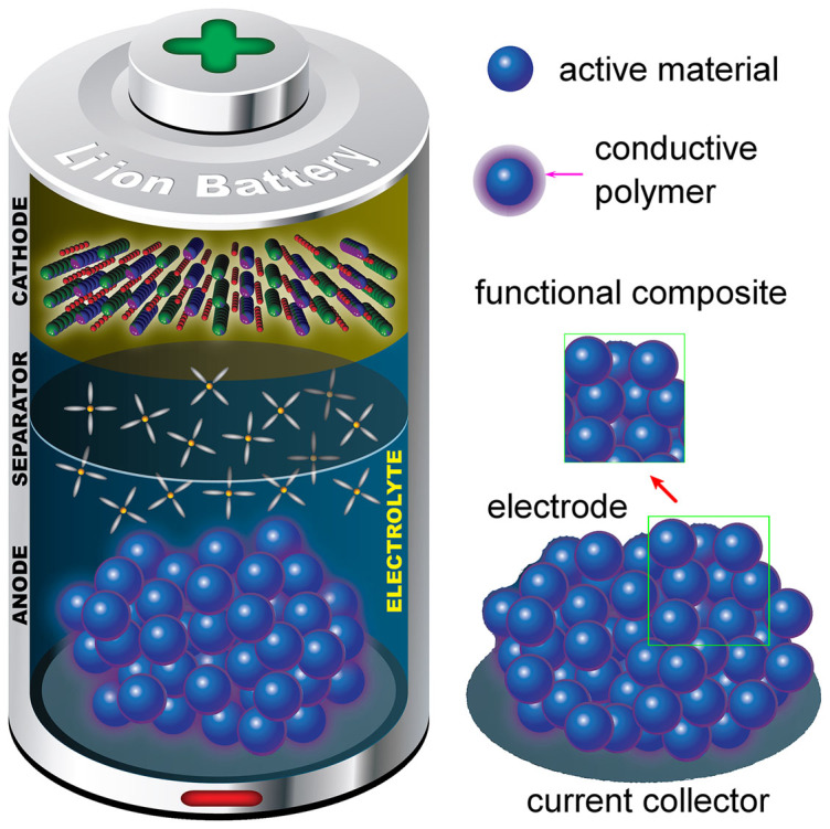
Figure 2. Electrochemical cycling performance of the SCP electrode; the inset shows the comparison of the first several cycles of the SCP electrode and the conventional Si electrode.
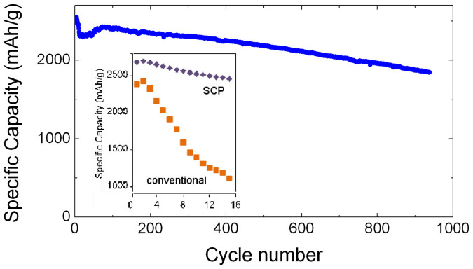
The specific capacity is referring to the loaded Si.
Results
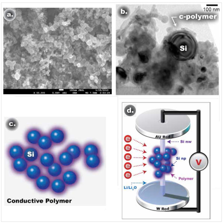
The microstructural features of the SCP electrode material were revealed by the SEM and TEM images shown in Fig. 3. The functional composite unit of the SCP is Si NPs wrapped by the conductive polymer matrix as schematically illustrated in Fig. 3(c). The conductive polymer is electrically conductive and keeps the Si NPs dispersed, while still bounded together. In contrary, the functional composite unit of the conventional Si anode is composed of Si NPs, the acetylene black carbon nanoparticles, and non-conductive polymer. As indicated by the TEM images of Fig. S1(a) in the Supplementary Information, the acetylene black carbon nanoparticles exhibit a porous morphology. The acetylene black carbon nanoparticles and Si NPs are bonded together by the non-conductive polymer as shown by the schematic drawing in Fig. S1(b). The acetylene black carbon nanoparticles act as conductive channels to increase the electrical conductivity of the whole electrode12. The performing characteristics of the batteries using these two functional materials are illustrated in Fig. 2. The battery with the SCP based anode shows not only a higher initial specific capacity, but also maintains a very good cycling stability up to ~938 cycles. In contrast, the electrode prepared by the traditional approach exhibits a lower initial capacity, which fades quickly upon cycling. The dramatic performance difference exhibited by these two materials is closely related to the difference of functional composite unit of these materials in response to lithium ion insertion and extraction. The structural evolution of functional composite prepared by both SCP and traditional method is evaluated using in-situ TEM observations as illustrated in Fig. 3(d). In specific, the structural evolution of both materials upon lithium insertion and extraction is examined and compared from the following three aspects: (1) individual Si NP; (2) the interaction between the individual Si NP and conductive polymer that is wrapping around the particle; and (3) mesoscale phenomenon.
Figure 3.
(a) SEM image of the SCP anode, (b)TEM image of the SCP anode; (c) schematic drawing of the SCP approach; (d) schematic drawing showing the in-situ TEM approach: a piece of the electrode including a few functional composite units is loaded on one single Si NW to form a nanobattery inside the TEM.
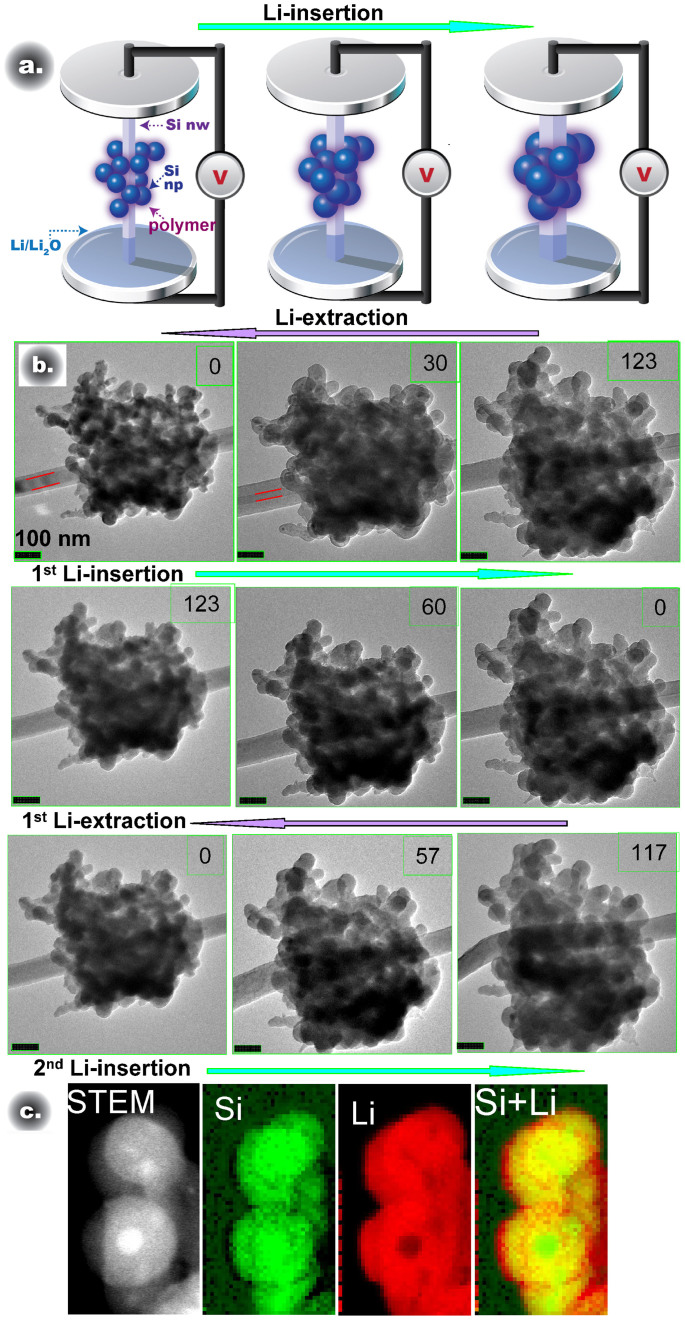
The microstructure evolution of the SCP anode materials during Li insertion and extraction processes with a cluster of material of typical dimension of ~700 nm is representatively shown in Fig. 4 The schematic drawing of Fig. 4(a) is just for the purpose of guiding the eyes for the reading of the images in Fig. 4(b). In the experimental setup, the Li ions were transported to the clustered material through the supporting Si nanowire. Therefore, during the electrochemical experiment, the Si nanowire was also lithiated and delithiated as indicated by the red lines in Fig. 4(b). In the first lithium insertion process, each Si NP is lithiated in a core-shell form, featuring a crystalline Si core and amorphous LixSi shell as shown by the image at 30 min. At 123 min, all the Si NPs inside the conductive polymer was nearly fully lithiated as indicated by the almost disappearing of the core. Upon delithiation, the individual particle gradually shrank as illustrated by the images from right to left in the middle row of Fig. 4(b). With the second lithium insertion, the individual particle expanded again as illustrated by the images from left to right in the third row of Fig. 4(b). The core-shell structural feature of individual Si NP can also be clearly seen in the captured movie S1–S3 in the Supplementary Information. The core-shell lithiation behavior of the particle is further confirmed by the STEM-EELS elemental mapping as illustrated in Fig. 4(c). The observation of the core-shell lithiation and delithiation of the individual Si NP embedded in the conductive polymer is consistent with the typical characteristics of lithiation of Si NP as reported in the previous publications6,17. The simultaneous lithiation of all Si NP within this cluster indicates a pervasive distribution of Li within this cluster, essentially demonstrating that the conductive polymer indeed serves as a media for fast transport of Li ions.
Figure 4.
(a) Schematic drawing showing the volume expansion of the Si anode on Si NW during lithium insertion and extraction; (b) Captured video frames of the in-situ TEM imaging during the lithium insertion and extraction processes in the SCP anode at different time; first row: 1st lithium insertion; second row: 1st lithium extraction; third row: 2nd lithium insertion (c) STEM image and elemental (Si, Li, Si + Li composite) maps obtained using EELS Si L edge and Li K edge during lithiation.
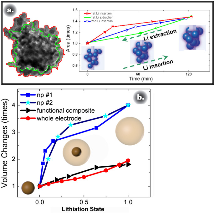
It is known that lithiation/delithiation of Si NP will lead to a volume expansion/shrinkage of ~400%. Fig. 4(b) and the Movies S1–S3 in the Supplementary Information clearly demonstrate that during the Li insertion and extraction, the topographic features of the particle clusters is reversibly conserved, demonstrating that the volume expansion/shrinkage of the Si NP is concordantly accommodated by the deformation of the conductive polymer that wrapped around the Si NP. This result is further confirmed by the quantitative analysis of the TEM images of the SCP material as illustrated in Fig. 5 (a), which traces the projected contour and the total area of cluster shown in Fig. 4 (b) upon repeated lithium insertion and extraction. Clearly, at the whole cluster scale, the volume and the contour of the cluster is reserved upon cyclic insertion and extraction of the lithium. The ability of the conductive polymer to expand and shrink coherently with the Si NPs plays a critical role in maintaining a good electronic conductivity and Li ion transport within the SCP material during the repeated electrochemical cycling. The conserved topographic feature and good electrical conductivity critically contribute to the dramatically enhanced cycling stability of the battery.
Figure 5.
(a) Comparison of the starting fresh state and lithiated state of the SCP anode and plot of the measured areas of the anode in the TEM image acquired at different time; (b) Comparison of the volume expansion of the whole electrode, functional composite, and single NP, the inset drawing in panel (b) shows the structure changes of the single Si NP during the lithiation process. (The volume expansion of np#1, np#2 is analyzed based on the data from McDowell et al in reference 17.)
The Fig. 5(b) compares the volume expansion of a single Si NP, SCP functional composite, and the whole electrode. In the plot of Fig. 5(b), the pristine state is denoted as 0; while the fully lithiated state is denoted as 1. The volume expansion of two Si NPs (labeled as np#1, np#2)17 and functional composite were all measured by in-situ TEM, while the volume expansion of the whole electrode was estimated using an in-situ electrochemical dilatometer measurement as illustrated by Fig. S2 in the Supplementary Information. The crystalline Si NPs shows a strong anisotropy in the volume expansion during lithiation, therefore the total volume expansion of the single NP is based on the lithiated area changes tracked by the TEM images (Fig. S3), while the total volume expansion is normalized to ~400%. The functional composite is composed of a large number of Si NPs of various orientations inside the polymer matrix, therefore during the lithiation, it will show an isotropic volume expansion. The volume expansion of the functional composite are calculated based on the projected area changes in the TEM images. The lithiation states are estimated as (the specific lithiation time of each state)/(the total lithiation time). In comparison, the area changes of the np#1 and np#2 and functional composite are plotted in Fig. S3. Fig. 5 clearly reveals that even the volume change of a single Si NP in the SCP is ~400%, the volume change of the functional composite is much smaller, approximately less than 100%. Further, it can be seen that the volume change of the functional material is consistent with that of the whole electrode. Therefore, the functional composite is the basic unit of the composite electrode. The behavior of the functional composite determines the cycling stability and capacity of the whole electrode.
Another important advantage of using SCP anodes is the prevention of the coalescence of the Si NPs during lithiation. As shown by previous studies6,16, upon lithiation, Si NPs or nanowires in contact can weld together, a process that is equivalent to the coarsening of particles during lithation. The coarsening of the particles will reduce the active surface area where Li ions interact with Si and decrease the rate performance of the Li-ion batteries. For the case of SCP, conformal coating of a thin conductive polymer layer on the surface of each Si NP prevents the welding of the active Si NPs during lithiation, which inherently contributes to the dimensional stability of the SCP anode and therefore the dramatically improved cycling stability and rate performance of the Li-ion batteries.
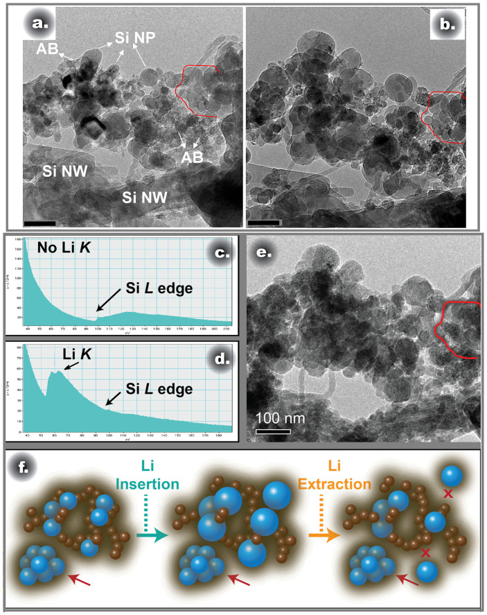
In contrast, the conventional composite material shows very different lithiation characteristics. The microstructure of the conventional functional composite of Si electrode is representatively shown in Fig. 6(a), featuring an aggregate of Si NPs and acetylene black carbon NPs bonded by non-conductive polymer. The acetylene black carbon NPs are used to increase the conductivity of the electrode. The acetylene black carbon NPs show sponge-like structure, while the Si NPs are solid round particles with dark diffraction contrast. The structural evolution of the cluster shown in Fig. 6(a) upon lithiation is illustrated in Fig. 6(b) and is further detailed by the captured movie shown in the Supplementary Information (Movie S4). Fundamentally, lithiation of a single Si NP follows the typical core-shell characteristics as similarly observed for the Si NPs in the SCP electrode. However, it can be noticed that a small cluster of Si NPs as circled by the red line did not show any volume change during the whole lithiation/delithiation process, indicating that these Si NPs were never lithiated. This observation is further confirmed by the STEM-EELS analysis as shown in Fig. 6 (c–d), highlighting a huge Li K edge peak collected on the particles with a volume expansion and the lack of Li K edge peak associated with the unlithiated particles as marked by the red line. Apparently, there are some Si NPs in the conventional composite remains inactive. Detailed observation reveals that the inactivity of the Si NPs is related to the disruption of the contact between the carbon NPs and the Si NPs, yielding a poor local electrical conductivity. The delithiated state of the region shown in Fig. 6(b) is illustrated in Fig. 6(e). Following the deep delithiation, voids can be noticed in the electrochemically active Si NPs. Formation of void is the consequence of the condensation of the vacancies generated by the removal of lithium ions, which has also been similarly observed by others as reported in the published literature6. Comparing the structural features of Fig. 6(a) and Fig. 6 (e), it can be seen that during the delithiation process, the lithiated Si NPs shrank, but the composite never returned to the innitial configuration of the pristine state. The structural evolution of the conventional composite described above is summarized by the schematic drawing shown in Fig. 6(f). Due to the poor conductivity of the Si NPs, they only lithiate if they are in direct contact with carbon particles. The Si NPs isolated from any carbon additives by non-conductive polymer cannot achieve a good electronic conductivity. Therefore, these Si NPs remain inactive in the electrode during the function of the battery. Fig. 6(f) also illustrates another possible scenario. Some Si NPs may initially indeed in close contact with the carbon NPs, however, the expansion/shrinkage of the Si NPs during the lithiaiton/delithiation may lead to the disruption of the contact, resulting in the electrical isolation phenomena as illustrated in Fig. 6(f).
Figure 6.
(a) TEM image of the starting state and (b) final state of lithiation of the conventional composite anode; (c) Li K edge and Si L edge from the region inside and (d) outside the region labeled in red; (e) final delithiated state of the conventional composite anode; (f) schematic drawing showing the structural evolution of the conventional composite anode during the lithium insertion and extraction.
The distinctive differences of the microstructural evolution of the functional materials based on SCP and conventional composite as summarized above provide clues as why the cycling reversibility of the conventional composite is not as good as the SCP. The lithiation process is largely influenced by the electronic conductivity of the Si-based composite. Without a good conductivity, the isolated Si NPs in the anode will never lithiated during the whole life time of the batteries. This explains why the initial specific energy density of the anode based on the conventional composite material is not as high as that of the SCP anode as observed in the electrochemical performance in Fig. 2(c). Further, the fast capacity fading of anode based on the conventional composite material (Fig. 2(c)) can be partially attributed to, among other factors such as solid electrolyte interface (SEI) layer thickening, the broken of the electrical contact between the carbon and Si NPs during the expansion/shrinkage of the Si NPs.
Discussion
Our results clearly reveal that the electronic conductivity is the limiting factor for the lithiation of the Si-based anode. For the electrode material prepared by the conventional method, associated with the difficulties on uniform mixing of the acetylene black additive carbon and Si NPs, fraction of the Si NPs remains inactive in the whole electrochemical cycling. Therefore, the electrochemical active loading of the Si NPs is less than the overall loading that nominally put into the battery cell. In addition, the contact of the acetylene black additive and Si NPs can be easily disrupted as a consequence of the significant expansion/contraction of the Si NP during lithiation/delithation, which directly contributes to a fast capacity fading of the Si-based anodes. In contrast, the SCP approach shows many advantages over the conventional approach. During the whole cycling of the conductive polymer/Si composite, all the Si NPs are electrochemically active and can be cycled stably and reversibly without further capacity loss. Therefore, our in-situ observation of the lithiation/delithiation study suggests that the SCP approach based on conductive polymer and Si NPs is a prefered method for preparation of Si NPs based electrode materials for a scale of industrial applications. If the conventional method is used, measures must be taken to ensure a good contact between Si NPs and the surrounding carbon NPs, therefore facilitating the increase of the loading of the active Si NPs in the electrode.
In summary, we probed the lithiation characteristics of two types of Si NPs based electrodes at the mesoscale using in-situ TEM. The functional composite unit can well represent the structural changes of the whole electrode during cycling. The SCP anode exhibits superior electrochemical cycling stability and higher energy density, which is attributed to a good and sustained electrical contact between the Si NP and the surrounding conductive polymer due to the resilient bonding between the conductive polymer and Si NPs. In contrary, the conventional Si NPs based anode shows obvious deficiency for establishing and maintain a good electrical contact between the Si NPs and the additives. Typically Si NPs that are away from the acetylene black additive carbon cannot be lithiated during cycling. The in-situ TEM observations directly pin-points the failure mechanism of the conventional Si composite as compared with SCP anode, which is in good agreement with the electrochemical performance data. The present results serve as an excellent example for linking mesoscale phenomenon with the properties of the real devise.
Methods
Conductive polymer Poly (9,9-dioctylfluorene-co-fluorenone-co-methylbenzoic ester) was used as Si electrode binder. The conductive polymer was designed and synthesized at Lawrence Berkeley National Lab and the detailed procedure has been reported in the literature12. Battery-grade acetylene black with an average particle size of 40 nm, a specific surface area of 60.4 m2/g, and a material density of 1.95 g/cm3 was acquired from Denka Singapore Private Ltd. PVDF KF1100 binder with a material density of 1.78 g/cm3 was supplied by Kureha, Japan. Anhydrous N-methylpyrrolidone NMP with 50 ppm of water content was purchased from Aldrich Chemical Co. Si NPs were purchased from American Elements and used without further purification. The particle size defined by the company is 50–70 nm. The composition of electrolyte is 1 M LiPF6 in EC and fluorinated ethylene carbonate (7:3 w/w) from Novolyte technologies of BASF. The Si/conductive polymer (SCP) electrode was made by dispersing a defined amount of Si NP in the conductive polymer/chlorobenzene solution to meet the desired Si:polymer weight ratios of 2:1. The Si/PVDF and acetylene black (conventional composite) electrode was made by dispersing a defined amount of Si, PVDF polymer and acetylene black in NMP solution to meet the desired Si/PVDF/acetylene black weight ratio of 2:0.8:0.2. The cell data reported are based on lithium metal as a counter electrode in coin cells. The voltage range is 0.01 V–1 V. The C-rate calculation of the Si-based electrode assumes that the Si has a theoretical capacity of 4200 mAh/g. The electrode is cycled at C/10 current rate. The detailed procedure of slurry mixing, electrode casting, and cell fabrication can be found in the literature20,21. The Si mass loading is 0.17 mg/cm2 for the tested batteries cells.
All processing are performed at Ar-filled glove box to avoid over oxidation of the lithium metal. For the in-situ TEM experiment, a piece of the electrode material was attached to a phosphorus-doped silicon nanowire, which was bounded to a gold rod using conductive epoxy. A piece of lithium metal was attached to a tungsten rod served as the counter electrode. A thin layer of Li2O formed on the lithium metal surface acts as the solid electrolyte in the nanobattery. The phosphorus-doped silicon NW acts as a bridge for efficient lithium ion transport. The nanobattery is placed into the TEM column for in-situ dynamical observation. Application of proper potential (±2 V) is used to drive the lithiation and delithiation processes. The loading of the sample into the microscope is performed using a Ar-filled glove bag. The total air exposure during the loading of the sample into the microscope is less than 2 s. A thin layer of the Li2O forms as a result of the air exposure, serving perfectly as the solid electrolyte layer. All the in-situ electrochemical tests were conducted on a Titan 80–300 kV scanning/transmission electron microscope (S/TEM) operated at 300 kV with a Nanofactory TEM scanning tunneling microscopy (STM) holder. The EELS spectra are taken with a Quantum model Gatan Image Filter with a 2 k*2 k pixel CCD.
Author Contributions
M.G., G.L. and C.M.W. designed the experiment, G.L. synthesized the material, X.C.X. carried out the electrode expansion experiment, M.G. carried out the in-situ work, M.G., G.L. and C.M.W. write the manuscript, C.M.W. supervised the work. S.T., D.R.B., J.G.Z., J.L. and N.D.B. discussed the work, all authors discussed the results and contributed to the writing of the manuscript.
Supplementary Material
Video 1
Video 2
Video 3
video4
Supplemary information
Acknowledgments
This work is supported by the Assistant Secretary for Energy Efficiency and Renewable Energy, Office of Vehicle Technologies of DOE under Contract No. DE-AC02-05CH11231,Subcontract No. 18769 under the Batteries for Advanced TransportationTechnologies (BATT) program. The in-situ TEM capability and associated technique development is supported by the Chemical Imaging Initiative at Pacific Northwest National Laboratory (PNNL). It was conducted under the Laboratory Directed Research and Development Program at PNNL, a multi-program national laboratory operated by Battelle under Contract DE-AC05-76RLO1830 for the U.S. Department of Energy (DOE). The work was conducted in the William R. Wiley Environmental Molecular Sciences Laboratory (EMSL), a national scientific user facility sponsored by DOE's Office of Biological and Environmental Research and located at PNNL. PNNL is operated by Battelle for the Department of Energy under Contract DE-AC05-76RLO1830. AK and JL acknowledge support by NSF DMR-1008104 and DMR-1120901.
References
- Kang B. & Ceder G. Battery materials for ultrafast charging and discharging. Nature 458, 190–193 (2009). [DOI] [PubMed] [Google Scholar]
- Liu X. H. & Huang J. Y. In situ TEM electrochemistry of anode materials in lithium ion batteries. Energy & Env. Sci. 4, 3844–3860 (2011). [Google Scholar]
- Chan C. K. et al. High-performance lithium battery anodes using silicon nanowires. Nat Nano. 3, 31–35 (2008). [DOI] [PubMed] [Google Scholar]
- Wu H. et al. Stable cycling of double-walled silicon nanotube battery anodes through solid-electrolyte interphase control. Nat Nano 7, 310–315 (2012). [DOI] [PubMed] [Google Scholar]
- Huang J. Y. et al. In Situ Observation of the Electrochemical Lithiation of a Single SnO2 Nanowire Electrode. Science 330, 1515–1520(2010). [DOI] [PubMed] [Google Scholar]
- Gu M. et al. In Situ TEM Study of Lithiation Behavior of Silicon Nanoparticles Attached to and Embedded in a Carbon Matrix. Acs Nano 6, 8439–8447(2012). [DOI] [PubMed] [Google Scholar]
- McDowell M. T. et al. Novel Size and Surface Oxide Effects in Silicon Nanowires as Lithium Battery Anodes. Nano Lett. 11, 4018–4025(2011). [DOI] [PubMed] [Google Scholar]
- Liu N. et al. A Yolk-Shell Design for Stabilized and Scalable Li-Ion Battery Alloy Anodes. Nano Lett. 12, 3315–3321(2012). [DOI] [PubMed] [Google Scholar]
- Gu M. et al. Formation of the Spinel Phase in the Layered Composite Cathode Used in Li-Ion Batteries. ACS Nano 7, 760–767(2012). [DOI] [PubMed] [Google Scholar]
- Ghassemi H., Au M., Chen N., Heiden P. A. & Yassar R. S. In Situ Electrochemical Lithiation/Delithiation Observation of Individual Amorphous Si Nanorods. ACS Nano 5, 7805–7811(2011). [DOI] [PubMed] [Google Scholar]
- Liu X. H. et al. Size-Dependent Fracture of Silicon Nanoparticles During Lithiation. ACS Nano 6, 1522–1531(2012). [DOI] [PubMed] [Google Scholar]
- Liu G. et al. Polymers with Tailored Electronic Structure for High Capacity Lithium Battery Electrodes. Adv. Mater. 23, 4679–4683(2011). [DOI] [PubMed] [Google Scholar]
- Wang C.-M. et al. In Situ TEM Investigation of Congruent Phase Transition and Structural Evolution of Nanostructured Silicon/Carbon Anode for Lithium Ion Batteries. Nano Lett. 12, 1624–1632(2012). [DOI] [PubMed] [Google Scholar]
- Park M.-H. et al. Silicon Nanotube Battery Anodes. Nano Lett. 9, 3844–3847(2009). [DOI] [PubMed] [Google Scholar]
- Lee S. W., McDowell M. T., Choi J. W. & Cui Y. Anomalous Shape Changes of Silicon Nanopillars by Electrochemical Lithiation. Nano Lett. 11, 3034–3039(2011). [DOI] [PubMed] [Google Scholar]
- Karki K. et al. Lithium-Assisted Electrochemical Welding in Silicon Nanowire Battery Electrodes. Nano Lett. 12, 1392–1397(2012). [DOI] [PubMed] [Google Scholar]
- McDowell M. T. et al. Studying the Kinetics of Crystalline Silicon Nanoparticle Lithiation with In Situ Transmission Electron Microscopy. Adv. Mater. 24, 6034–6041(2012). [DOI] [PubMed] [Google Scholar]
- Liu X. H. et al. Self-Limiting Lithiation in Silicon Nanowires. ACS Nano 7, 1495–1503(2012). [DOI] [PubMed] [Google Scholar]
- Gu M. et al. Electronic Origin for the Phase Transition from Amorphous LixSi to Crystalline Li15Si4. ACS Nano 7, 6303–6309 (2013). [DOI] [PubMed] [Google Scholar]
- Liu G. et al. Optimization of acetylene black conductive additive and PVDF composition for high-power rechargeable lithium-ion cells. J. Electrochem. Soc. 154, A1129–A1134 (2007). [Google Scholar]
- Liu G. et al. Effects of Various Conductive Additive and Polymeric Binder Contents on the Performance of a Lithium-Ion Composite Cathode. J. Electrochem. Soc. 155, A887–A892 (2008). [Google Scholar]
Associated Data
This section collects any data citations, data availability statements, or supplementary materials included in this article.
Supplementary Materials
Video 1
Video 2
Video 3
video4
Supplemary information


