Abstract
Accurate and efficient treatment of electrostatics is a crucial step in computational analyses of biomolecular structures and dynamics. In this study, we have explored a second-order finite-difference numerical method to solve the widely used Poisson–Boltzmann equation for electrostatic analyses of realistic bio-molecules. The so-called immersed interface method was first validated and found to be consistent with the classical weighted harmonic averaging method for a diversified set of test biomolecules. The numerical accuracy and convergence behaviors of the new method were next analyzed in its computation of numerical reaction field grid potentials, energies, and atomic solvation forces. Overall similar convergence behaviors were observed as those by the classical method. Interestingly, the new method was found to deliver more accurate and better-converged grid potentials than the classical method on or nearby the molecular surface, though the numerical advantage of the new method is reduced when grid potentials are extrapolated to the molecular surface. Our exploratory study indicates the need for further improving interpolation/extrapolation schemes in addition to the developments of higher-order numerical methods that have attracted most attention in the field.
Keywords: Poisson-Boltzmann equation, Finite difference method, Immersed interface method, Continuum solvent models
1. Introduction
Electrostatic interactions play important roles in the structural, dynamic and functional properties of biomolecules. Accurate and efficient treatment of electrostatics is thus crucial in computational analyses of biomolecular structures and dynamics. A closely related issue is the modeling of water molecules and their electrostatic interactions with biomolecules that must be considered for any realistic representation of biomolecules at physiological conditions. Since most particles in a molecular model represent water molecules solvating the target biomolecules, treating these water molecules implicitly offers an opportunity to reach higher computational efficiency and to model more complex biomolecular systems. A class of successful implicit solvent models based on the Poisson–Boltzmann equation (PBE) has been widely to model solvated electrostatic interactions for biomolecular applications after years of basic research and development.
In this implicit/continuum solvent treatment, the solute molecule is treated as a low dielectric constant region and the solvent is treated as a high dielectric constant region. A number of fixed interior point charges are located atomic centers. Since analytic solution of the PBE can be achieved only in a few specific cases with simple solute geometry, numerical solutions of the PBE are almost always needed for biomolecular applications. Among the numerical solution methods, finite-difference methods (FDM) [1–14], finite-element methods (FEM) [15–24] and boundary-element methods (BEM) [25–42] are mostly used. In these three methods, FDM has the advantage of being straightforward and physically transparent. However, if a direct discretization is used without considering the discontinuity in the dielectric constant, the numerical solutions tend to have large errors, and the errors are particularly obvious near the solute–solvent interface. To overcome this problem, Davis and McCammon proposed a harmonic average (HA) method to approach the approximate dielectric constant near surface in 1991 [43]. Efforts have also been reported recently by Wei and co-workers and Li and co-workers to develop higher accuracy interface schemes, the immersed interface method (IIM) and the matched interface and boundary (MIB) method, to improve numerical accuracy of the PBE solution [44–50]. The idea of IIM is to enforce the interface conditions into the finite-difference schemes at grid points near the interface. On the other hand, the scheme of MIB is enforcing the lowest-order jump condition repeatedly to achieve the high-order jump condition. Besides these higher-order numerical schemes, there are also proposals to improve implicit solvent models, including coupling electrostatic and nonelectrostatic interactions within the implicit solvation treatment [51–55] and using level set to help the definition of solvent–solute interface [56,57].
Even with constant community-wide efforts to improve the efficiency and accuracy of numerical PBE models, mathematical and computational challenges remain in adoption of the methods to routine molecular dynamics simulations. One challenge is the difficulty of assigning forces related to the dielectric boundary to individual atoms, and many efforts have been invested to develop methods to compute electrostatic forces [7,15,21,30,58–76]. Another challenge is how to achieve convergence of numerical energy and forces with respect to the resolution of the solute–solvent boundary and charge representation efficiently both in terms of CPU time and memory usage[43,77]. Indeed, numerical forces are especially difficult to reach a high enough accuracy because forces are derivatives of energies that are always harder than energies to compute by numerical approaches. These issues still limit the applications of numerical PBE models to calculations involving static biomolecular structures only.
In this study, we explored a higher-accuracy numerical scheme, the immersed interface method (IIM), to solve the PBE [44]. The idea of IIM is to enforce the interface conditions into the finite-difference schemes at grid points near the interface. Our preliminary analysis on the IIM for a well-studied analytical system indicated its promises for biomolecular applications [45]. Here we extended the IIM to realistic biomolecules to investigate its performance of electrostatic properties, such as gird reaction field potential, atomic reaction field energy and atomic reaction field forces. In addition, interface properties such as potentials and electric fields were also carefully analyzed for future applications in dielectric stress and pressure calculations.
2. Methods
2.1. Finite-difference/finite-volume method
Without loss of generality, we focus on the Poisson’s equation in this study since the Boltzmann term is nonzero only outside the Stern layer, which is typically set 2 Å away from the dielectric interface where the dielectric constant is smooth. The partial differential equation
| (1) |
establishes a relation between charge density (ρ) and electrostatic potential (φ), given a predefined dielectric distribution function (ε) for a solvated molecule.
The FDM is a widely utilized numerical method to discretize partial differential equations. With FDM, a uniform Cartesian grid is used to discretize a finite rectangle box containing the solvated molecule. The grid points are numbered as (i, j, k), i = 1, …, xm, j = 1, …, ym, k = 1, …, zm, where xm, ym and zm are the numbers of points along the x, y, and z axes, respectively. The spacing between neighbor points is uniformly set to be h. Charge density ρ(i, j, k) in FDM is given as ρ(i, j, k) = q(i, j, k)/h3, where the q(i, j, k) is the total charge within the cubic volume centered at (i, j, k). Under this discretization scheme, the Poisson’s equation can be discretized as
| (2) |
where h is the spacing in each dimension; φ(i, j, k) is the potential on grid (i, j, k), and φ(i ± 1, j, k), φ(i, j ± 1, k) and φ(i, j, k ± 1) are defined similarly; is the dielectric constant at the mid-point between grids (i, j, k) and (i − 1, j, k), and and are defined similarly; is the dielectric constant at the mid-point between grids (i, j, k) and (i + 1, j, k), and and are defined similarly. The dielectric constant is related to the dielectric interface treatment to be discussed below. The solute atomic charge distribution is mapped onto grid points using a mapping procedure. Here the trilinear mapping method was used [78]. More detailed implementation information can be found in our recent works [9,11,13,14,79].
2.2. Interface treatment: Harmonic average
Harmonic average is a well-established interface treatment method. For FDM, the dielectric constant is difficult to set when the two neighboring grid points belong to different dielectric regions. The electrostatic interface/jump condition must be satisfied across the interface between the different dielectric regions. One simple treatment is the use of harmonic average (HA) of the two dielectric constants at the interface midpoints to satisfy the jump condition in each dimension [43]. For example, if (i − 1, j, k) and (i, j, k) belong to different dielectric regions, there must be an interface point on the grid edge between (i − 1, j, k) and (i, j, k). In HA is defined as
| (3) |
where a is the distance from the interface point to grid point (i − 1, j, k), and b is the distance from the same interface point to grid point (i, j, k).
Obviously, this is an approximated treatment, but this strategy has been shown to improve the convergence of reaction field energies respect to the grid spacing [43].
2.3. Interface treatment: Immersed interface method
A more systematic way for interface treatment is the immersed interface method (IIM) [44]. In IIM the interface is often represented by the zero level set of a Lipchitz continuous function (often the signed distance function) ϕ(x, y, z):
| (4) |
where Γ is the interface, Ω− is the inside dielectric region and Ω+ is the outside dielectric regions. After defining
| (5) |
a grid point can be classified irregular if , and regular if otherwise.
Discretized partial differential equation appears the same as Eq. (2) at regular grid points
| (6) |
where f (i, j, k) = −4πq(i, j, k)/h3 is used to denote the point charge term. For each irregular grid point, a new finite-difference equation involving 27 points including the central irregular grid point and its 26 neighboring points in a 3 × 3 × 3 grid cube is constructed to minimize the local truncation error while satisfying the interface conditions
| (7) |
Here [u]α is defined as [u]α = u(α+) − u(α−) = limx→α+ u(x) − limx→α− u(x).
The new finite difference equation at irregular point (i, j, k) can be written as
| (8) |
where ns represents all the 27 grid points, γm are the undetermined coefficients, and C(i, j, k) is an undetermined correction term, chosen to minimize the local truncation error while satisfying the interface conditions of [φ]Γ = w and [εφn]Γ = ν. The basic idea of IIM is to determine γm in Eq. (8) at the irregular points so that the second-order global accuracy is obtained as in an interface-free problem with the finite-difference/finite-volume discretization scheme. Since only grid points nearby the interface are involved, it is sufficient to have an O(h) local truncation error at those points to reach the goal [44,80]. The detailed procedure has been documented in our previous works [45].
2.4. Removal of charge singularity
Point charge models are widely used in molecular dynamics of biomolecules, yet the representation of point charges is delta function that is difficult to solve by PB equations. Eq. (2) shows that the finite-volume discretization scheme overcomes this problem by resorting to the integral form of the PBE. Thus the total charge, instead of the singular charge density, appears as a discretized form q(i, j, k) in the right side of Eq. (2) at grid point (i, j, k). However, such a treatment distorts the otherwise singular Coulombic potential [67].
Several advanced strategies are also available to remove the charge singularity [19,47,81,82]. Here we adopted an efficient strategy developed by our group [83]. Briefly, the reaction field potential (φRF) is solved in the solute region (Ω−) and the total potential (φ = φRF + φC) is solved in the solvent region (Ω+). Here φC is the Coulombic potential, satisfying ε−∇2φC = −4πρ [83]. The respective equations for φRF and φ are
| (9) |
where N(φ) represents the Boltzmann term and is set to zero in the current study [83]. The corresponding interface conditions across Γ are then changed as
| (10) |
As shown in Eq. (10), the Coulombic potential is needed on the interface [83].
2.5. Electrostatic energy and forces
2.5.1. Reaction field energy and forces
The reaction field energy (ΔG) is calculated as
| (11) |
If the charge singularity is removed, it is simply
| (12) |
The reaction field forces (qE) are obtained as
| (13) |
2.5.2. Interface potential and electrostatic field
After solving the finite-difference equations, only potential values at grid points are known. To obtain potential or electrostatic field at any position (x0, y0, z0), we utilized the one-sided least-square fitting method [80]. Briefly, there are N(≥ 10) equations of the second-order 3D-Taylor expansion, respectively, for the N(≥ 10) grid points with respect to the origin, (x0, y0, z0), i.e. the surface point of interest
| (14) |
These equations are involved to determine the coefficients Aα, α = 1, …, 10, where f(x, y, z)i is the potential of grid point (x, y, z)i, and (x − x0)i, (y − y0)i and (z − z0)i are the relative position vector components of grid point (x, y, z)i with respect to the origin (x0, y0, z0). The N(≥ 10) grid points are chosen to be within a 3 × 3 × 3 cubic grid, where the center point is the nearest grid point to the origin. Since we are to conduct a one-sided extrapolation, only the inside grid points are included. Within the cubic grid, about half of the 27 points are at either side of the interface so that the number of grid points N(≥ 10) selected in the fitting is in the range of 10 ~ 18. The coefficients Aα, α = 1, …, 10 are then solved by the Singular Value Decomposition (SVD) algorithm as summarized below.
In the extrapolation problem, N(≥ 10) linear equations from Eq. (14) are used to determine ten coefficients Aα, α = 1, …, 10. Symbolically, it can be written as
| (15) |
where ai,1 = 1, ai,2 = (x − x0)i, ai,3 = (y − y0)i, ai,4 = (z − z0)i, , ai,8 = (x − x0)i(y − y0)i, ai,9 = (y − y0)i(z − z0)i, ai,10 = (x − x0)i(z − z0)i, fi = fi(x, y, z).
Eq. (15) is simplified further below as
| (16) |
where X is the matrix of ai,j, β is the matrix of Ai and Y is the matrix of fi. To solve this over-determined linear system (i.e. the number of equations is larger than the number of unknowns.), a linear regression problem needs to be completed via the standard least square minimization protocol [84]. One way is to replace X by its SVD in carrying out the regression of Y on X, as follows. This procedure is also called principal components regression [84].
| (17) |
where U is a N × N unitary matrix, V* is a 10 × 10 unitary matrix and Σi,i (i = 1, …, 10) are the 10 singular values of matrix X. Next β can be calculated directly by multiplying (XTX)−1XT to both sides of Eq. (17). Because U, V* and Σ are known, the solution β is obtained as
| (18) |
Once the linear system is solved, the potential and gradient of potential (field) at position (x0, y0, z0) are obtained by the following relation:
| (19) |
2.6. Linear system solvers
The coefficient matrices produced by the IIM are asymmetric and positive-indefinite. Therefore the conjugate gradient method or other closely related methods are not suitable for solving these linear systems. In this study, three general methods, Generalized Minimal RESidual method (GMRES), BiConjugate Gradient method (BiCG), and algebraic multigrid (AMG) are investigated to solve these asymmetry linear systems.
Similar to the conjugate gradient method (CG), GMRES constructs a sequence of orthogonal vectors and minimize the residue along these vectors in sequence. However, for symmetric matrices, only one previous vector is necessary in the construction of the new orthogonal vector. To handle asymmetric matrices, it is necessary to remember all previous vectors and use the Arnoldi iteration to construct the new vector orthogonal to all the previous vectors. GMRES can be summarized as the following pseudo code:
|
BiCG is a generalization of conjugate gradient method (CG) for asymmetric and positive-indefinite systems. It constructs two sequences of vectors rl and r̃l which are biorthogonal, that is , i ≠ j. However it constructs the new direction of minimization without the knowledge of previous vectors. Therefore it uses less memory. Apparently, when the matrix A is symmetric, BiCG goes back to CG. However, the method requires two matrix–vector productions at each step. BiCG can be summarized as the following pseudo code:
| 1. Let l = 0. Compute residue r0 = b − Ax0 and set r̃0 = r0, p0 = r0. |
| 2. Set l = l + 1. |
| 3. Calculate . |
| 4. If l = 1 |
| set pl = rl−1, p̃l = r̃l−1 |
| Else |
| set βl−1 = ρl−1/ρl−2, pl = rl−1 + βl−1 pl−1, p̃l = r̃l−1 + βl−1 p̃l−1 |
| 5. Calculate ql = Apl, q̃l = ATp̃l, , xl = xl−1 + αlpl, rl = rl−1 − αlql, r̃l = r̃l−1 − αlq̃l |
| 6. Calculate the norm of residue ||rl||. If ||rl||/||b|| is less than a predefined convergence threshold δ, output xl as the solution. Otherwise go to step 2. |
Algebraic multigrid (AMG) was also explored, which is a general multigrid method that does not require any specific structure in the linear system. Further, it does not utilize the geometric information in its operators as in typical multigrid methods. Its generality is important because the regular pattern in the linear system from IIM is lost. According to the original linear system, AMG automatically constructs a series of gradually smaller liner systems, whether the coefficients are continuous or discontinuous. The grids at the finer level Ch are split into two subsets: one set (CH) includes the grids kept at the coarser level, and the other set (FH) includes the rest. Then the interpolation operator can be defined as
| (20) |
The restriction operator is the reverse of interpolation operator, and the relaxation operator uses Gauss–Seidel. More grids in subset CH likely make the interpolation at grids in subset FH more accurate. On the other hand more grids in CH consume more computational resource. Therefore a good grid-splitting algorithm has to balance the interpolation accuracy and computational cost. The detail of the grid-splitting algorithm is reviewed in Ref. [85]. In this study, we investigated the performance of a publically available AMG method, AMG1R5, as implemented by Ruge, Stüben and Hempel [86].
3. Test cases and other computational details
All computational procedures were implemented in the Amber12/PBSA program [9,11,13,14,79]. The molecular surface was defined using a revised density function strategy that combines the concept of modified van der Waals surface with an optimized density function [57,87]. In this strategy, the density function was utilized to smooth the modified van der Waals surface to remove any crevices. The dielectric constant inside ε− was 1.0, and the dielectric constant outside ε+ was set at 80.0. All molecules were assigned the charges of Cornell et al. [88] and the modified Bondi radii, except that the smallest hydrogen radii were reset to 1.0 Å, i.e. as in the original Bondi radius definition. The probe radius was 1.4 Å. The finite-difference convergence criterion was set to be 10−5. And the Poisson’s equation was solved with the charge singularity removed [83].
In the following, the consistency between the new IIM and the classical WHA methods were first investigated to validate the implementation of the new method. The full test cases consisted of 579 biomolecular structures including proteins, nucleic acids and short peptides in the Amber benchmark suite [89]. The atom numbers of these biomolecules range from 247 to 8254 and their geometries are highly diversified. These validation runs were conducted with a grid spacing of 1/2 Å. Then four small molecular complexes, adenine–thymine (AT), guanine-cytosine (GC), arginine-aspartic acid (RD) and lysine-aspartic acid (KD) were chosen to analyze the convergence of reaction grid potentials, energies and atomic forces. Molecular surface potentials and fields were also investigated. The grid spacings were chosen as 1/2, 3/8, 1/4, 3/16, 1/8, and 1/16 Å in the convergence analysis. Eight representative proteins were then selected to compare the performances of GMRES, BiCG, and AMG linear system solvers. Here, the atom numbers of the selected proteins vary from 1619 to 4211. The detail sizes of the selected proteins are showed in Table 1. The total numbers of grid points of these proteins vary from ~2 × 10⁶ to 107. The tested convergence criteria range from 10−1 to 10−9.
Table 1.
Eight selected proteins, their No. of atoms (Natom), and No. of x direction grid points times No. of y direction grid points times No. of z direction grid points (Ngrid).
| PROTEIN | Natom | Ngrid |
|---|---|---|
| 1a23 | 2955 | 175 × 159 × 143 |
| 1bci | 1969 | 159 × 111 × 111 |
| 1bxd | 2439 | 191 × 207 × 175 |
| 1d8v | 4211 | 175 × 191 × 175 |
| 1fyb | 1619 | 127 × 175 × 207 |
| 1inz | 2413 | 207 × 271 × 191 |
| 1qto | 1817 | 143 × 143 × 143 |
| 2pcf | 3884 | 239 × 223 × 159 |
4. Results and discussion
In the following, the IIM implementation was first validated by comparing the numerical reaction field energies of a large set of diversified biomolecules computed by both the IIM and the well-established WHA method. Next the influences of enforcing interface conditions upon the precision of reaction field grid potentials, energies, forces, interface potentials and interface fields were analyzed on a few selected small biomolecular complexes. Finally the performance of different linear system solvers was discussed, which is important for the applications of the IIM in typical biomolecular systems.
4.1. Overall consistency of IIM and WHA on tested biomolecules
As discussed in the Methods section, both the IIM and the WHA method intend to enforce the dielectric boundary conditions, though the WHA method is only able to achieve this approximately. Both methods utilize the same numerically represented surface and the same set of irregular grid points, i.e. grid points with heterogeneous dielectric grid edges. The treatments of the irregular grid points are clearly different between the two methods, as described in detail in the Methods section.
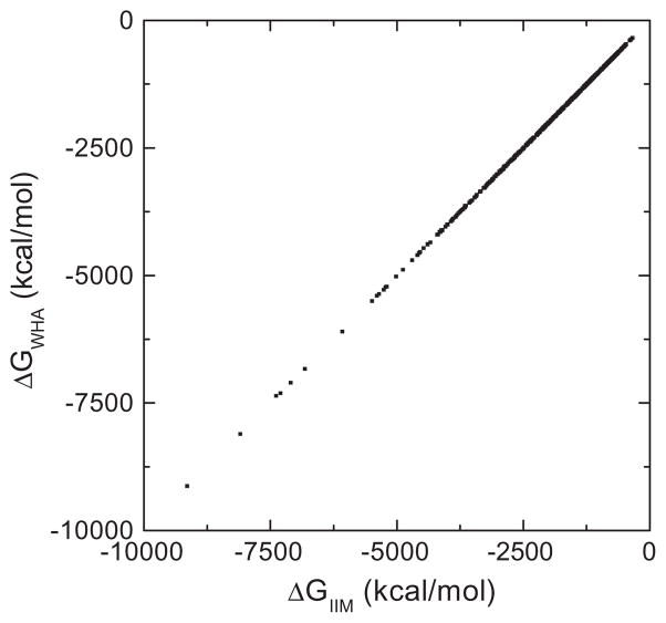
To confirm the implementation of the IIM, reaction field energies of 579 biomolecules were calculated by the IIM and the WHA. The correlation between the numerical energies was shown in Fig. 1. Clearly, a very high correlation can be found between the two different algorithms. Detailed analysis shows that the Pearson correlation coefficient is 1.0000 between the two sets of data, the linear regression slope is 1.0014 (with a fixed offset of zero), and the RMS relative deviation is 0.0026 between the two sets of data. These data show a very high overall consistency between the two methods.
Fig. 1.
Correlation of reaction field energies (ΔG) by IIM and WHA at 1/2 Å grid spacing for the Amber training set of 579 biomolecules. The Pearson correlation coefficient is 1.0000 and the linear regression slope is 1.0014 (with fixed offset of zero).
4.2. Convergence of reaction field grid potentials, energies and forces
After validating the overall consistency of WHA and IIM, four small molecular complexes (AT, GC, RD, and KD as described in Methods) were chosen to analyze the convergence of reaction field grid potentials, atomic reaction field energies, and atomic reaction field forces because these small systems allow us to use a very fine grid spacing (1/16 Å) for high-accuracy numerical calculations. Here the numerical results at the 1/16 Å grid were chosen as benchmark due to the lack of analytical solutions for these realistic molecules. Indeed, only very simple models such as monopolar or dipolar spheres allow analytical solution [45].
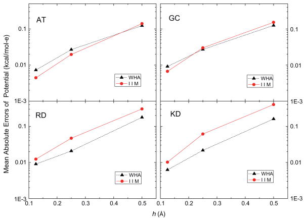
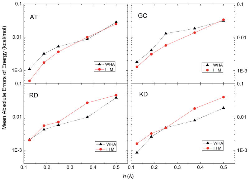
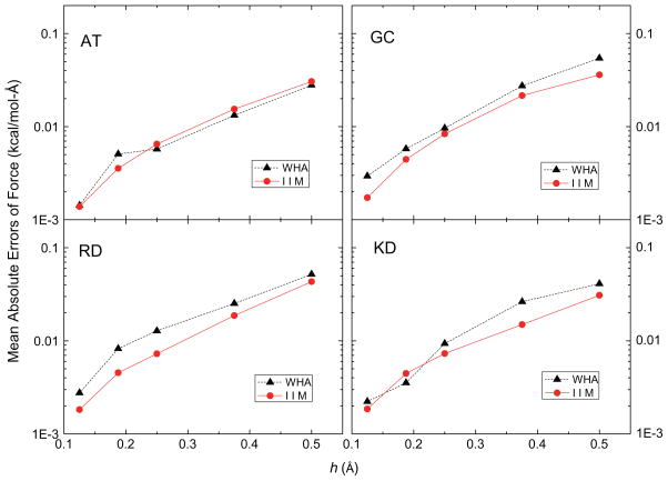
In this analysis, the accuracy of the grid potentials and fields nearby each atom was studied using a more detailed calculation instead of the lump-sum total energy that tends to hide local numerical error due to cancellation. Fig. 2 shows that the mean absolute errors of the grid potentials at the eight grid points nearby each atom follow similar overall convergence trends, decreasing by a factor of around twenty as the grid spacing is reduced from 1/2 to 1/8 Å (with the solutions at 1/16 Å as benchmark). These grid points are the eight nearest grid points in the 1/2 Å FDPB grid whose potentials were computed with different grid spacings, 1/2 Å, 1/4 Å, 1/8 Å and 1/16 Å, respectively, so their potentials can be looked up without any interpolation. Next, the eight nearest grid points of each atom at 1/2 Å, 1/4 Å, 1/8 Å and 1/16 Å FDPB grid were chosen to interpolate the energies and forces with the trilinear mapping method [78]. Fig. 3 shows the mean absolute errors of atomic reaction field energies, and Fig. 4 presents the mean absolute errors of the atomic reaction field forces. Fig. 3 clearly shows that the convergence trends of atomic reaction field energies follow an overall consistent trend between WHA and IIM. The mean absolute errors go down approximately by a factor of twenty when the grid spacings reduce from 1/2 Å to 1/8 Å. Fig. 4 shows that the convergences of atomic reaction field forces are similar to those of energies and potentials, decreasing from ~0.04 to ~0.002 kcal/mol-Å as the grid spacing is reduced from 1/2 to 1/8 Å. The convergence curves in Figs. 2–4 are not very smooth because these small molecular systems only have 20–40 atoms each, so the numbers of sample sizes are not large enough to smooth out the numerical fluctuations. In summary, overall similar convergence behaviors by the two methods are observed in the reaction field grid potentials, atomic reaction field energies, and atomic reaction field forces in four tested small complexes.
Fig. 2.
Mean absolute errors of reaction field potentials at the 8 nearest finite-difference grid points of each atom (kcal/mol-e) versus grid spacing h (Å) with respect to those calculated at the fine grid spacing of 1/16 Å for AT, GC, RD and KD dimers, respectively.
Fig. 3.
Mean absolute errors of reaction field energies at each atom (kcal/mol) versus grid spacing h (Å) with respect to those calculated at the fine grid spacing of 1/16 Å for AT, GC, RD and KD dimers, respectively.
Fig. 4.
Mean absolute errors of reaction field forces at each atom (kcal/mol-Å) versus grid spacing h (Å) with respect to those calculated at the fine grid spacing of 1/16 Å for AT, GC, RD and KD dimers, respectively.
4.3. Convergence of molecular surface potential and field
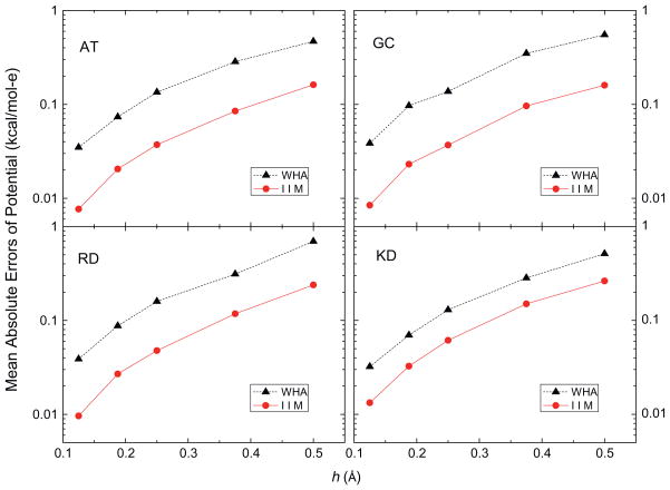
The IIM intends to offer more accurate numerical solution by enforcing interface jump conditions. Thus there is a good reason to expect IIM to behave more robustly on and nearby the molecular surface. Here AT, GC, RD and KD were again utilized to analyze the quality of numerical surface potential and field by IIM and WHA. As shown in Fig. 5, mean absolute errors of inside irregular grid potentials decrease with reducing grid spacing from 1/2 Å to 1/8 Å for both methods: for IIM the errors change from ~0.2 to ~0.01 kcal/mol-e and for WHA the errors change from ~0.6 to ~0.03 kcal/mol-e. The trend lines indicate a significantly consistent smaller errors in the IIM as the inside grid points approach the molecular surface. Comparing with the above analyses on atomic reaction field potentials and atomic reaction field energies, the data show that the benefit of enforcing interface conditions mainly dominates on and nearby the molecular surface, and the benefit is reduced at locations well within the molecular interior.
Fig. 5.
Mean absolute errors of reaction field potentials at the irregular grid points (inside, kcal/mol-e) versus grid spacing h (Å) with respect to those calculated at the fine grid spacing of 1/16 Å for AT, GC, RD and KD dimers, respectively.
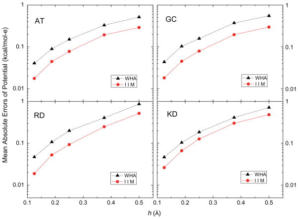
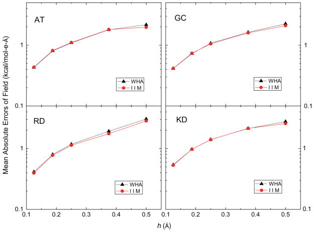
Extrapolated potential and field on the molecular surface were analyzed next, which are important for dielectric stress and pressure calculation. The extrapolation method is the one-sided second-order least square fitting method described in the Method section. Fig. 6 shows the convergence of the extrapolated interface potentials, giving that the mean absolute errors of IIM are smaller than those of WHA, though the gap between the two convergence trend lines is smaller than that in Fig. 5 for the irregular grid points. Here the errors in IIM change from ~0.4 to ~0.02 kcal/mol-e while the errors in WHA is nearly twice as much as those in IIM, from ~0.7 to ~0.04 kcal/mol-e. On the other hand, Fig. 7 shows that errors with the almost same order of magnitude were observed in the surface field for both IIM and WHA, reducing from ~2 to ~0.5 kcal/mol-e-Å. There are two possible strategies to improve the extrapolated field on the molecular surface. The first is to apply higher order fitting. Since field is the derivative of potential, the performance of second-order fitting of field should be similar with first-order fitting of potential. Thus, we can expect the third-order fitting of field performs similarly as second-order fitting of potential. The second strategy is to utilize grid points on both sides of the surface during interpolation and to consider the jump conditions across the molecular surface. We will explore these more elaborative methods in a future study.
Fig. 6.
Mean absolute errors of potentials on the molecular surface (inside, kcal/mol-e) versus grid spacing h (Å) with respect to those calculated at the fine grid spacing of 1/16 Å for AT, GC, RD and KD dimers, respectively. A second-order least square fitting method was used in all tests.
Fig. 7.
Mean absolute errors of reaction fields on the molecular surface (inside, kcal/mol-e-Å) versus grid spacing h (Å) with respect to those calculated at the fine grid spacing of 1/16 Å for AT, GC, RD and KD dimers, respectively. A second-order least square fitting method was used in all tests.
4.4. Some analysis on IIM matrices and linear system solvers
4.4.1. Some analysis on IIM matrices
Before comparing the performance of tested linear system solvers, the condition numbers of IIM matrices were first analyzed as this is a key issue determining the computational efficiency of linear solvers. For a linear algebraic system A·x = b, the condition number is defined as cond(A) = ||A|| ||A−1||, which shows the rough rate at which solution x changes with respect to the change in b and A. As reviewed in our previous work [45], the IIM coefficient matrix was constructed to preserve maximum principal. For such matrices the same upper bound holds for the condition number, and can be estimated as where ε(x, y, z) is the dielectric constant [80]. These have been discussed in detail elsewhere, for example in [80,90]. The IIM was designed to achieve this goal by guaranteeing that the IIM coefficient matrix is an M-matrix that is diagonally dominant and invertible.
Here we further demonstrate numerically that the IIM coefficient matrices are well conditioned with the four tested small molecular complexes, AT, GC, RD and KD. The grid spacing was chosen as 1 Å to keep the coefficient matrices within manageable sizes. Their reciprocal condition numbers are 7.4 × 10⁻³, 1.2 × 10⁻², 1.2 × 10⁻², and 3.0 × 10⁻², respectively. These numerical analyses agree with the upper-bound estimation mentioned above, indicating the tested matrices are stable enough, i.e. the solutions do not change dramatically when the right hand sides are bounded as is the chase of atomic charges in typical biomolecular force fields. Based on these theoretical discussion and numerical tests, it is reasonable to assume that the IIM matrices are well conditioned on realistic biomolecules. Indeed convergence is observed for all tested biomolecules.
4.4.2. Linear system solvers
Given the theoretical and numerical analysis demonstrating that the IIM linear systems are well conditioned, we tested three linear system solvers for potential biomolecular applications. It is instructive first to discuss the memory usage of each solver since the huge memory usage is always the bottleneck in applying numerical PBE methods in biomolecular simulations. As described in Methods, both the coefficient matrix and the right-hand-side term are needed during iteration in all three solvers. In our program, the coefficient matrix is stored in the triad format, requiring 3Nnz real numbers, where Nnz is the number of non-zero element in the coefficient matrix. The right-hand-side term needs Ngrid real numbers, where Ngrid is the number of the FDPB grid points. Our test shows that AMG needs the most memory: it needs to store 46Ngrid real numbers and 49Ngrid integers. This can be a huge overhead, considering the very high dimensionalities that are often encountered in biomolecular applications. In contrast, both BiCG and GMRES use less memory. BiCG needs ~Nnz + 8Ngrid real numbers and ~Nnz + 4Ngrid integers. Because GMRES retains its previous vectors, it needs more real numbers, ~Nnz + Ngrid×(Nsave + 7) real numbers in total, where Nsave is the number of the saved vectors, set to be 10 in this test. In addition, GMRES also needs ~Nnz + 4Ngrid integers.
An additional disadvantage of AMG is its numerical instability: 5 out of the 579 tested molecules were not able to converge. These failures are unlikely to be memory-related because the tests on many larger molecules were successfully converged. In contrast, tests performed by the GMRES and BiCG solvers on the same set of molecules are both 100% successfully completed. It is difficult to trace down the limitation of the AMG method because of the black-box package [86] that was utilized in our development. Apparently development of a brand new AMG routine may resolve the issue, but it is clearly beyond the scope of this study.
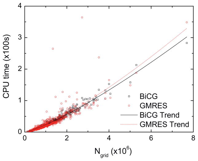
Next the timing of the three tested solvers was analyzed. For the 574 tested molecules that AMG was able to complete successfully, their CPU times are also the longest compared with GMRES and BiCG (data not shown). Thus the two more robust solvers, GMRES and BiCG, were given more attention below in the following comparative analysis. Fig. 8 shows the CPU time versus the number of grid points (Ngrid). All 579 molecules in the Amber test set were used in this analysis. Nonlinear fits of the timing data indicate that the performance of BiCG is slightly better, scaling as GMRES scales as . However, there are significant deviations in the GMRES trend line, indicating a less robust performance among individual tested molecules.
Fig. 8.
CPU time versus the number of grids (Ngrid) for GMRES and BiCG, respectively. Convergence criterion (relative) is set to be 10−6.
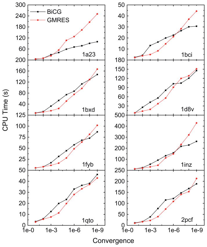
Finally the relation between CPU time and the relative convergence criterion is analyzed and shown in Fig. 9. The eight proteins listed in Table 1 were used as examples. Overall, similar performances between GMRES and BiCG were observed, consistent with the above analysis on the relation between CPU time and the linear system sizes. However, the performance of GMRES fluctuates greatly even for the eight relatively smaller proteins. For example, GMRES is about one to two times slower than BiCG for 1a23 and 1inz to reach the relative convergence criterion of 10−9.
Fig. 9.
CPU time versus convergence criterion for GMRES and BiCG, respectively, for the eight proteins listed in Table 1.
5. Conclusion and future directions
We have explored a high-accuracy numerical scheme, the immersed interface method, to solve the Poisson–Boltzmann equation for biomolecular applications. The implementation of the new method was first validated for applications on realistic bio-molecules using a diversified set of biomolecules by comparing reaction field energies computed by the new method and the well-established classical weighted harmonic averaging method. Overall a very high correlation was found between the two sets of energies, given the clearly different treatments of the interface grid points as described in detail in the Methods section.
With the overall consistency of the two methods, we went ahead to analyze the convergence of reaction field grid potentials, atomic reaction field energies, and atomic reaction field forces using several tested small molecular complexes. Overall a similar convergence behavior was observed with the mean absolute errors that decrease by a factor of around twenty from 1/2 Å to 1/8 Å grid spacings for both methods. We further analyzed the quality of numerical surface potential and field by the two methods. The convergence behavior of boundary grid potentials is similar for both methods, but apparently smaller errors were observed for the new method, which were around 1/3 of those for the classical method. Surface potentials and fields, extrapolated by the one-sided second-order least square fitting method, converge similarly as boundary grid potentials for both methods. Nevertheless, larger errors were observed for the surface potentials compared with the errors of boundary grid potentials, though the errors of new method is still around half of the classical method, showing the advantage in surface potentials analyses. However, the errors in the surface field by the new method are virtually identical to those by the classical method.
Apparently we need to further improve the extrapolation scheme on the molecular surface to bring out the higher accuracy observed on the grid potentials by utilizing the higher ordered new method. In the current study, extrapolated surface field, as one of key physical quantities, has not benefitted from using the higher accuracy scheme, limiting the realistic application prospects of the new method. We are actively exploring to improve the accuracy of the surface field from developing higher-order fitting procedures and applying higher weights to grid potentials closer to the surface point of interest. We are also developing two-sided least square fitting methods to utilize the dielectric boundary condition to reduce fitting errors.
In summary, to be able to apply the PB model in molecular simulations of biomolecules is the ultimate motivation of our effort documented here. Apparently, solver accuracy is only one aspect of the grant challenge. We have discussed the limitation of force extrapolation/interpolation that must also be addressed to reach our goal. Equally important are the issues related to the development of stable algorithms for force calculation as we discussed in our papers elsewhere and the model scalability/efficiency on modern computing platforms. Improvements in these areas are all important for us to utilize the PB model in routine molecular simulations.
Acknowledgments
This work is supported in part by NIH (GM093040 & GM079383).
References
- 1.Klapper I, Hagstrom R, Fine R, Sharp K, Honig B. Focusing of electric fields in the active site of copper-zinc superoxide dismutase effects of ionic strength and amino acid modification. Proteins: Struct, Funct, Genet. 1986;1:47–59. doi: 10.1002/prot.340010109. [DOI] [PubMed] [Google Scholar]
- 2.Davis ME, McCammon JA. Solving the finite-difference linearized Poisson–Boltzmann equation – a comparison of relaxation and conjugate-gradient methods. J Comput Chem. 1989;10:386–391. [Google Scholar]
- 3.Nicholls A, Honig B. A rapid finite-difference algorithm, utilizing successive over-relaxation to solve the Poisson–Boltzmann equation. J Comput Chem. 1991;12:435–445. [Google Scholar]
- 4.Luty BA, Davis ME, McCammon JA. Solving the finite-difference nonlinear Poisson–Boltzmann equation. J Comput Chem. 1992;13:1114–1118. [Google Scholar]
- 5.Holst M, Saied F. Multigrid solution of the Poisson–Boltzmann equation. J Comput Chem. 1993;14:105–113. [Google Scholar]
- 6.Forsten KE, Kozack RE, Lauffenburger DA, Subramaniam S. Numerical-solution of the nonlinear Poisson–Boltzmann equation for a membrane-electrolyte system. J Phys Chem. 1994;98:5580–5586. [Google Scholar]
- 7.Im W, Beglov D, Roux B. Continuum solvation model: computation of electrostatic forces from numerical solutions to the Poisson–Boltzmann equation. Comput Phys Commun. 1998;111:59–75. [Google Scholar]
- 8.Rocchia W, Alexov E, Honig B. Extending the applicability of the nonlinear Poisson–Boltzmann equation: multiple dielectric constants and multivalent ions. J Phys Chem B. 2001;105:6507–6514. [Google Scholar]
- 9.Luo R, David L, Gilson MK. Accelerated Poisson–Boltzmann calculations for static and dynamic systems. J Comput Chem. 2002;23:1244–1253. doi: 10.1002/jcc.10120. [DOI] [PubMed] [Google Scholar]
- 10.Bashford D. An object-oriented programming suite for electrostatic effects in biological molecules. Lecture Notes in Comput Sci. 1997;1343:233–240. [Google Scholar]
- 11.Lu Q, Luo R. A Poisson–Boltzmann dynamics method with nonperiodic boundary condition. J Chem Phys. 2003;119:11035–11047. [Google Scholar]
- 12.Prabhu NV, Zhu PJ, Sharp KA. Implementation and testing of stable, fast implicit solvation in molecular dynamics using the smooth-permittivity finite difference Poisson–Boltzmann method. J Comput Chem. 2004;25:2049–2064. doi: 10.1002/jcc.20138. [DOI] [PubMed] [Google Scholar]
- 13.Wang J, Luo R. Assessment of linear finite-difference Poisson–Boltzmann solvers. J Comput Chem. 2010;31:1689–1698. doi: 10.1002/jcc.21456. [DOI] [PMC free article] [PubMed] [Google Scholar]
- 14.Cai Q, Hsieh MJ, Wang J, Luo R. Performance of nonlinear finite-difference Poisson–Boltzmann solvers. J Chem Theory Comput. 2010;6:203–211. doi: 10.1021/ct900381r. [DOI] [PMC free article] [PubMed] [Google Scholar]
- 15.Cortis CM, Friesner RA. Numerical solution of the Poisson–Boltzmann equation using tetrahedral finite-element meshes. J Comput Chem. 1997;18:1591–1608. [Google Scholar]
- 16.Baker N, Holst M, Wang F. Adaptive multilevel finite element solution of the Poisson–Boltzmann equation II. Refinement at solvent-accessible surfaces in biomolecular systems. J Comput Chem. 2000;21:1343–1352. [Google Scholar]
- 17.Holst M, Baker N, Wang F. Adaptive multilevel finite element solution of the Poisson–Boltzmann equation I. Algorithms and examples. J Comput Chem. 2000;21:1319–1342. [Google Scholar]
- 18.Shestakov AI, Milovich JL, Noy A. Solution of the nonlinear Poisson–Boltzmann equation using pseudo-transient continuation and the finite element method. J Colloid Interface Sci. 2002;247:62–79. doi: 10.1006/jcis.2001.8033. [DOI] [PubMed] [Google Scholar]
- 19.Chen L, Holst MJ, Xu JC. The finite element approximation of the nonlinear Poisson–Boltzmann equation. Siam J Numer Anal. 2007;45:2298–2320. [Google Scholar]
- 20.Xie D, Zhou S. A new minimization protocol for solving nonlinear Poisson–Boltzmann mortar finite element equation. BIT. 2007;47:853–871. [Google Scholar]
- 21.Friedrichs M, Zhou RH, Edinger SR, Friesner RA. Poisson–Boltzmann analytical gradients for molecular modeling calculations. J Phys Chem B. 1999;103:3057–3061. [Google Scholar]
- 22.Bond SD, Chaudhry JH, Cyr EC, Olson LN. A first-order system least-squares finite element method for the Poisson–Boltzmann equation. J Comput Chem. 2010;31:1625–1635. doi: 10.1002/jcc.21446. [DOI] [PubMed] [Google Scholar]
- 23.Lu B, Holst MJ, McCammon JA, Zhou YC. Poisson–Nernst–Planck equations for simulating biomolecular diffusion-reaction processes I: finite element solutions. J Comput Phys. 2010;229:6979–6994. doi: 10.1016/j.jcp.2010.05.035. [DOI] [PMC free article] [PubMed] [Google Scholar]
- 24.Lu BZ, Zhou YC. Poisson–Nernst–Planck equations for simulating biomolecular diffusion-reaction processes ii: size effects on ionic distributions and diffusion-reaction rates. Biophys J. 2011;100:2475–2485. doi: 10.1016/j.bpj.2011.03.059. [DOI] [PMC free article] [PubMed] [Google Scholar]
- 25.Miertus S, Scrocco E, Tomasi J. Electrostatic interaction of a solute with a continuum – a direct utilization of abinitio molecular potentials for the prevision of solvent effects. Chem Phys. 1981;55:117–129. [Google Scholar]
- 26.Hoshi H, Sakurai M, Inoue Y, Chujo R. Medium effects on the molecular electronic-structure. 1. the formulation of a theory for the estimation of a molecular electronic-structure surrounded by an anisotropic medium. J Chem Phys. 1987;87:1107–1115. [Google Scholar]
- 27.Zauhar RJ, Morgan RS. The rigorous computation of the molecular electric-potential. J Comput Chem. 1988;9:171–187. [Google Scholar]
- 28.Rashin AA. Hydration Phenomena, Classical electrostatics, and the boundary element method. J Phys Chem. 1990;94:1725–1733. [Google Scholar]
- 29.Yoon BJ, Lenhoff AM. A boundary element method for molecular electrostatics with electrolyte effects. J Comput Chem. 1990;11:1080–1086. [Google Scholar]
- 30.Juffer AH, Botta EFF, Vankeulen BAM, Vanderploeg A, Berendsen HJC. The electric-potential of a macromolecule in a solvent – a fundamental approach. J Comput Phys. 1991;97:144–171. [Google Scholar]
- 31.Zhou HX. Boundary-element solution of macromolecular electrostatics –interaction energy between 2 proteins. Biophys J. 1993;65:955–963. doi: 10.1016/S0006-3495(93)81094-4. [DOI] [PMC free article] [PubMed] [Google Scholar]
- 32.Bharadwaj R, Windemuth A, Sridharan S, Honig B, Nicholls A. The fast multipole boundary-element method for molecular electrostatics – an optimal approach for large systems. J Comput Chem. 1995;16:898–913. [Google Scholar]
- 33.Purisima EO, Nilar SH. A simple yet accurate boundary-element method for continuum dielectric calculations. J Comput Chem. 1995;16:681–689. [Google Scholar]
- 34.Liang J, Subramaniam S. Computation of molecular electrostatics with boundary element methods. Biophys J. 1997;73:1830–1841. doi: 10.1016/S0006-3495(97)78213-4. [DOI] [PMC free article] [PubMed] [Google Scholar]
- 35.Vorobjev YN, Scheraga HA. A fast adaptive multigrid boundary element method for macromolecular electrostatic computations in a solvent. J Comput Chem. 1997;18:569–583. [Google Scholar]
- 36.Totrov M, Abagyan R. Rapid boundary element solvation electrostatics calculations in folding simulations: successful folding of a 23-residue peptide. Biopolymers. 2001;60:124–133. doi: 10.1002/1097-0282(2001)60:2<124::AID-BIP1008>3.0.CO;2-S. [DOI] [PubMed] [Google Scholar]
- 37.Boschitsch AH, Fenley MO, Zhou HX. Fast boundary element method for the linear Poisson–Boltzmann equation. J Phys Chem B. 2002;106:2741–2754. [Google Scholar]
- 38.Lu BZ, Cheng XL, Huang JF, McCammon JA. Order N algorithm for computation of electrostatic interactions in biomolecular systems. Proc of the Natl Acad of Sci USA. 2006;103:19314–19319. doi: 10.1073/pnas.0605166103. [DOI] [PMC free article] [PubMed] [Google Scholar]
- 39.Lu BZ, Cheng XL, Hou TJ, McCammon JA. Calculation of the Maxwell stress tensor and the Poisson–Boltzmann force on a solvated molecular surface using hypersingular boundary integrals. J Chem Phys. 2005;123:084904. doi: 10.1063/1.2008252. [DOI] [PubMed] [Google Scholar]
- 40.Lu BZ, Zhang DQ, McCammon JA. Computation of electrostatic forces between solvated molecules determined by the Poisson–Boltzmann equation using a boundary element method. J Chem Phys. 2005;122:214102. doi: 10.1063/1.1924448. [DOI] [PubMed] [Google Scholar]
- 41.Lu BZ, Cheng XL, Huang JF, McCammon JA. An adaptive fast multipole boundary element method for Poisson–Boltzmann electrostatics. J Chem Theory Comput. 2009;5:1692–1699. doi: 10.1021/ct900083k. [DOI] [PMC free article] [PubMed] [Google Scholar]
- 42.Bajaj C, Chen SC, Rand A. An efficient higher-order fast multipole boundary element solution for Poisson–Boltzmann-based molecular electrostatics. Siam J Sci Comput. 2011;33:826–848. doi: 10.1137/090764645. [DOI] [PMC free article] [PubMed] [Google Scholar]
- 43.Davis ME, Mccammon JA. Dielectric boundary smoothing in finite-difference solutions of the Poisson equation – an approach to improve accuracy and convergence. J Comput Chem. 1991;12:909–912. [Google Scholar]
- 44.LeVeque RJ, Li ZL. The immersed interface method for elliptic equations with discontinuous coefficients and singular sources. Siam J Numer Anal. 1994;31:1019–1044. [Google Scholar]
- 45.Wang J, Cai Q, Li ZL, Zhao HK, Luo R. Achieving energy conservation in Poisson–Boltzmann molecular dynamics: accuracy and precision with finite-difference algorithms. Chem Phys Lett. 2009;468:112–118. doi: 10.1016/j.cplett.2008.12.049. [DOI] [PMC free article] [PubMed] [Google Scholar]
- 46.Zhou YC, Zhao S, Feig M, Wei GW. High order matched interface and boundary method for elliptic equations with discontinuous coefficients and singular sources. J Comput Phys. 2006;213:1–30. [Google Scholar]
- 47.Geng WH, Yu SN, Wei GW. Treatment of charge singularities in implicit solvent models. J Chem Phys. 2007;127:114106. doi: 10.1063/1.2768064. [DOI] [PubMed] [Google Scholar]
- 48.Yu SN, Wei GW. Three-dimensional matched interface and boundary (MIB) method for treating geometric singularities. J Comput Phys. 2007;227:602–632. [Google Scholar]
- 49.Zhou YC, Feig M, Wei GW. Highly accurate biomolecular electrostatics in continuum dielectric environments. J Comput Chem. 2008;29:87–97. doi: 10.1002/jcc.20769. [DOI] [PubMed] [Google Scholar]
- 50.Zheng Q, Yang SY, Wei GW. Biomolecular surface construction by PDE transform. Int J Numer Meth Bio. 2012;28:291–316. doi: 10.1002/cnm.1469. [DOI] [PMC free article] [PubMed] [Google Scholar]
- 51.Dzubiella J, Swanson JMJ, McCammon JA. Coupling nonpolar and polar solvation free energies in implicit solvent models. J Chem Phys. 2006;124:084905. doi: 10.1063/1.2171192. [DOI] [PubMed] [Google Scholar]
- 52.Dzubiella J, Swanson JMJ, McCammon JA. Coupling hydrophobicity, dispersion, and electrostatics in continuum solvent models. Phys Rev Lett. 2006;96:0872. doi: 10.1103/PhysRevLett.96.087802. [DOI] [PubMed] [Google Scholar]
- 53.Cheng LT, Dzubiella J, McCammon JA, Li B. Application of the level-set method to the implicit solvation of nonpolar molecules. J Chem Phys. 2007;127:084503. doi: 10.1063/1.2757169. [DOI] [PubMed] [Google Scholar]
- 54.Chen Z, Zhao S, Chun J, Thomas DG, Baker NA, Bates PW, Wei GW. Variational approach for nonpolar solvation analysis. J Chem Phys. 2012;137:084101. doi: 10.1063/1.4745084. [DOI] [PMC free article] [PubMed] [Google Scholar]
- 55.Thomas DG, Chun J, Chen Z, Wei GW, Baker NA. Parameterization of a geometric flow implicit solvation model. J Comput Chem. 2013;34:687–695. doi: 10.1002/jcc.23181. [DOI] [PMC free article] [PubMed] [Google Scholar]
- 56.Wang J, Cai Q, Xiang Y, Luo R. Reducing grid dependence in finite-difference Poisson–Boltzmann calculations. J Chem Theory Comput. 2012;8:2741–2751. doi: 10.1021/ct300341d. [DOI] [PMC free article] [PubMed] [Google Scholar]
- 57.Botello-Smith WM, Liu XP, Cai Q, Li ZL, Zhao HK, Luo R. Numerical Poisson–Boltzmann model for continuum membrane systems. Chem Phys Lett. 2013;555:274–281. doi: 10.1016/j.cplett.2012.10.081. [DOI] [PMC free article] [PubMed] [Google Scholar]
- 58.Davis ME, Madura JD, Mccammon JA. The University-of-Houston Brownian dynamics program. Biophys J. 1990;57:A415–A415. [Google Scholar]
- 59.Sharp K. Incorporating solvent and ion screening into molecular-dynamics using the finite-difference Poisson–Boltzmann method. J Comput Chem. 1991;12:454–468. [Google Scholar]
- 60.Niedermeier C, Schulten K. Molecular-dynamics simulations in heterogeneous dielectrica and Debye-Huckel media – application to the protein bovine pancreatic trypsin-inhibitor. Mol Simul. 1992;8:361–387. [Google Scholar]
- 61.Gilson MK, Davis ME, Luty BA, McCammon JA. Computation of electrostatic forces on solvated molecules using the Poisson–Boltzmann equation. J Phys Chem. 1993;97:3591–3600. doi: 10.1063/1.1924448. [DOI] [PubMed] [Google Scholar]
- 62.Gilson MK. Molecular-dynamics simulation with a continuum electrostatic model of the solvent. J Comput Chem. 1995;16:1081–1095. [Google Scholar]
- 63.Rashin AA. Electrostatics of ion ion interactions in solution. J Phys Chem. 1989;93:4664–4669. [Google Scholar]
- 64.Vorobjev YN, Grant JA, Scheraga HA. A combined iterative and boundary element approach for solution of the nonlinear Poisson–Boltzmann equation. J Am Chem Soc. 1992;114:3189–3196. [Google Scholar]
- 65.Yoon BJ, Lenhoff AM. Computation of the electrostatic interaction energy between a protein and a charged surface. J Phys Chem. 1992;96:3130–3134. [Google Scholar]
- 66.Zauhar RJ, Morgan RS. A new method for computing the macromolecular electric-potential. J Mol Biol. 1985;186:815–820. doi: 10.1016/0022-2836(85)90399-7. [DOI] [PubMed] [Google Scholar]
- 67.Luty BA, Davis ME, McCammon JA. Electrostatic energy calculations by a finite-difference method – rapid calculation of charge-solvent interaction energies. J Comput Chem. 1992;13:768–771. [Google Scholar]
- 68.Cortis CM, Friesner RA. An automatic three-dimensional finite element mesh generation system for the Poisson–Boltzmann equation. J Comput Chem. 1997;18:1570–1590. [Google Scholar]
- 69.Landau LD, Lifshitz EM, Pitaevskii LP. Electrodynamics of Continuous Media. Pergamon Press; Oxford: 1984. [Google Scholar]
- 70.Che J, Dzubiella J, Li B, McCammon JA. Electrostatic free energy and its variations in implicit solvent models. J Phys Chem B. 2008;112:3058–3069. doi: 10.1021/jp7101012. [DOI] [PubMed] [Google Scholar]
- 71.Cai Q, Ye X, Wang J, Luo R. Dielectric boundary force in numerical Poisson–Boltzmann methods: theory and numerical strategies. Chem Phys Lett. 2011;514:368–373. doi: 10.1016/j.cplett.2011.08.067. [DOI] [PMC free article] [PubMed] [Google Scholar]
- 72.Li B, Cheng X, Zhang Z. Dielectric boundary force in molecular solvation with the Poisson–Boltzmann free energy: a shape derivative approach. Siam J Appl Math. 2011;71:2093–2111. doi: 10.1137/110826436. [DOI] [PMC free article] [PubMed] [Google Scholar]
- 73.Cai Q, Ye X, Luo R. Dielectric pressure in continuum electrostatic solvation of biomolecules. Phys Chem Chem Phys. 2012;14:15917–15925. doi: 10.1039/c2cp43237d. [DOI] [PMC free article] [PubMed] [Google Scholar]
- 74.Zauhar RJ. The incorporation of hydration forces determined by continuum electrostatics into molecular mechanics simulations. J Comput Chem. 1991;12:575–583. [Google Scholar]
- 75.Davis ME, Mccammon JA. Calculating electrostatic forces from grid-calculated potentials. J Comput Chem. 1990;11:401–409. [Google Scholar]
- 76.Xiao L, Cai Q, Ye X, Wang J, Luo R. Electrostatic forces in the Poisson–Boltzmann systems. J Chem Phys. 2013;139:094106. doi: 10.1063/1.4819471. [DOI] [PMC free article] [PubMed] [Google Scholar]
- 77.Bruccoleri RE. Grid positioning independence and the reduction of self-energy in the solution of the Poisson–Boltzmann equation. J Comput Chem. 1993;14:1417–1422. [Google Scholar]
- 78.Edmonds DT, Rogers NK, Sternberg MJE. Regular representation of irregular charge-distributions application to the electrostatic potentials of globular-proteins. Mol Phys. 1984;52:1487–1494. [Google Scholar]
- 79.Cai Q, Ye X, Wang J, Luo R. On-the-fly numerical surface integration for finite-difference Poisson–Boltzmann methods. J Chem Theory Comput. 2011;7:3608–3619. doi: 10.1021/ct200389p. [DOI] [PMC free article] [PubMed] [Google Scholar]
- 80.Li ZL, Ito K. The Immersed Interface Method: Numerical Solutions of PDEs Involving Interfaces and Irregular Domains. SIAM, Society for Industrial and Applied Mathematics; Philadelphia: 2006. [Google Scholar]
- 81.Zhou ZX, Payne P, Vasquez M, Kuhn N, Levitt M. Finite-difference solution of the Poisson–Boltzmann equation: complete elimination of self-energy. J Comput Chem. 1996;17:1344–1351. doi: 10.1002/(SICI)1096-987X(199608)17:11<1344::AID-JCC7>3.0.CO;2-M. [DOI] [PubMed] [Google Scholar]
- 82.Chern IL, Liu JG, Wang WC. Accurate evaluation of electrostatics for macromolecules in solution. Methods Appl Anal. 2003;10:309–328. [Google Scholar]
- 83.Cai Q, Wang J, Zhao HK, Luo R. On removal of charge singularity in Poisson–Boltzmann equation. J Chem Phys. 2009;130:145101. doi: 10.1063/1.3099708. [DOI] [PubMed] [Google Scholar]
- 84.Mandel J. Use of the singular value decomposition in regression-analysis. Am Stat. 1982;36:15–24. [Google Scholar]
- 85.Stuben K. A review of algebraic multigrid. J Comput Appl Math. 2001;128:281–309. [Google Scholar]
- 86.Ruge JW, Stüben K. Algebraic multigrid. In: McCormick SF, editor. Multigrid Methods, Frontiers in Applied Mathematics. Vol. 3. SIAM; Philadelphia: 1987. pp. 73–130. [Google Scholar]
- 87.Liu XP, Wang CH, Wang J, Li ZL, Zhao HK, Luo R. Exploring a charge-central strategy in the solution of Poisson’s equation for biomolecular applications. Phys Chem Chem Phys. 2013;15:129–141. doi: 10.1039/c2cp41894k. [DOI] [PMC free article] [PubMed] [Google Scholar]
- 88.Cornell WD, Cieplak P, Bayly CI, Gould IR, Merz KM, Ferguson DM, Spellmeyer DC, Fox T, Caldwell JW, Kollman PA. A 2nd generation force-field for the simulation of proteins, nucleic-acids, and organic-molecules. J Am Chem Soc. 1995;117:5179–5197. [Google Scholar]
- 89.Case DA, Darden TA, Cheatham TE, III, Simmerling CL, Wang J, Duke RE, Luo R, Crowley M, Walker RC, Zhang W, Merz KM, Wang B, Hayik A, Roitberg A, Seabra G, Kolossvary I, Wong KF, Paesani F, Vanicek J, WX, Brozell SR, Steinbrecher T, Gohlke H, Yang L, Tan C, Mongan J, Hornak V, Cui G, Mathews DH, Seetin MG, Sagui C, Babin V, Kollman PA. Amber. Vol. 10. University of California; San Francisco: 2008. [Google Scholar]
- 90.Li ZL, Ito K. Maximum principle preserving schemes for interface problems with discontinuous coefficients. Siam J Sci Comput. 2001;23:339–361. [Google Scholar]


