1. INTRODUCTION
Two major energy-related problems confront the world in the next 50 years. First, increased worldwide competition for gradually depleting fossil fuel reserves (derived from past photosynthesis) will lead to higher costs, both monetarily and politically. Second, atmospheric CO2 levels are at their highest recorded level since records began. Further increases are predicted to produce large and uncontrollable impacts on the world climate. These projected impacts extend beyond climate to ocean acidification, because the ocean is a major sink for atmospheric CO2.1 Providing a future energy supply that is secure and CO2-neutral will require switching to nonfossil energy sources such as wind, solar, nuclear, and geothermal energy and developing methods for transforming the energy produced by these new sources into forms that can be stored, transported, and used upon demand.
Carbon dioxide is the ultimate source of the fossil fuels used in our daily lives. These fossil fuels exist as gases, liquids, and solids, from which we can select the form most suitable for a particular application. This flexibility in fuel choice will be beneficial for the foreseeable future. The process that drives carbon fixation into these fuels is photosynthesis, the biological conversion of sunlight, water, and carbon dioxide into reduced organic materials. Photosynthesis occurs on a very large scale. An estimated 385 × 109 tons of carbon dioxide are fixed annually net,2 and the gross value is larger by a factor of 2.3
Pathways for CO2 fixation have evolved over billions of years and use diverse mechanisms and enzymes for processing CO2 by making C–H and C–C bonds and cleaving C–O bonds. Research on homogeneous and heterogeneous catalysts for CO2 and CO reduction has also contributed to our understanding of C–C and C–H bond formation reactions as well as C–O bond cleavage reactions involved in the production of synthetic fuels. Significant scientific and economic imperatives thus motivate the development of carbon dioxide as a feedstock for fuels. According to the 2008 Bell/DOE report,4 “The major obstacle preventing efficient conversion of carbon dioxide into energy-bearing products is the lack of catalysts…” This background exemplifies the challenges that must be addressed. These considerations led to a workshop on CO2 chemistry carried out under the aegis of the Council on Chemical and Biochemical Sciences of the Basic Energy Sciences Division of the United States Department of Energy. Held in the fall of 2011, the workshop had the purpose of assessing synergistic contributions of the catalysis and biological communities to the problem of converting carbon dioxide directly into fuels.
All biological systems must extract energy from their environments to carry out the metabolic processes associated with life itself. Living organisms have evolved to exist in an amazing variety of environments, and they can use and interconvert energy from a variety of sources. In addition to the six known metabolic pathways involved in the biological fixation of CO2 into organic carbon, there are also important pathways that produce and use H2, reduce N2 to ammonia, oxidize water, and reduce oxygen. Thus, via these elemental cycles, biological systems have essentially developed their own H2, methanol, ethanol, nitrogen, etc., economies. In addition, these biological economies are scalable, from the level of a single microorganism to the microbial community and to the worldwide ecosystems that play important roles in global carbon, hydrogen, nitrogen, and oxygen cycles. The enzymes required to carry out these important metabolic pathways have evolved over billions of years, and they use readily abundant materials from the environment to achieve these important energy conversion processes. All of these metabolic pathways involve the storage and utilization of energy in the form of chemical bonds, and our ability to carry out these same transformations in a controlled and productive manner, independent of natural biological systems, will be critical to our future energy security.
Our central premise is that researchers in catalysis science can benefit from a deep understanding of these important metabolic processes. Complementarily, biochemists can learn by studying how catalytic scientists view these same chemical transformations promoted by synthetic catalysts. From these studies, hypotheses can be developed and tested through manipulation of enzyme structure and by synthesizing simple molecular catalysts to incorporate different structural features of the enzymes. It is hoped that these studies will lead to new and useful concepts in catalyst design for fuel production and utilization. This Review describes the results of a workshop held to explore these concepts in regard to the development of new and more efficient catalytic processes for the conversion of CO2 to a variety of carbon-based fuels.
The organization of this overview/Review is as follows: after this introduction, the second section briefly explores how interactions between the catalysis and biological communities have been fruitful in developing new catalysts for the reduction of protons to hydrogen, the simplest fuel generation reaction. The third section provides a concise summary of fundamentals of the chemistry and biochemistry of CO2. The fourth section assesses the state of the art in both biological and chemical reduction of CO2 by two electrons to form either carbon monoxide (CO) or formate (HCOO−). It also attempts to identify common principles between biological and synthetic catalysts and productive areas for future research. The fifth section explores both biological and chemical processes that result in the reduction of CO2 beyond the level of CO and formate, again seeking to identify common principles and productive areas of future research. The sixth section explores the formation of carbon–carbon bonds in biological and chemical systems in the same vein as the other sections. A seventh section addresses the role of non-redox reactions of CO2 in biological systems and their role in carbon metabolism, with a parallel discussion of chemical systems. In the eighth section, the topics of electrode modification, photochemical systems, and tandem catalysis are briefly discussed. These areas may be important for developing practical systems for CO2 reduction, and they share the common theme of coupling chemical reactions. The final two sections describe some of the cross-cutting activities that are critical for advancing the science underpinning catalyst development and a summary of issues common to both biological and chemical systems to achieve practical catalysts that are suitable for the reduction of CO2 to fuels.
2. PRODUCTIVE INTERACTIONS BETWEEN THE BIOLOGICAL AND CATALYSIS COMMUNITIES: HYDROGENASES AND THEIR MIMICS AS AN EXAMPLE
As stated above, our central premise is that catalytic scientists can learn by studying metabolic processes in nature, and biological scientists can learn from the study of these same chemical transformations promoted by synthetic catalysts. An important example of such interactions can be found between the biological and chemical communities studying synthetic and natural catalysts for H2 production and oxidation. The recognition that organometallic complexes exist at the active site of these enzymes has led naturally to productive interactions among enzymologists and protein crystallographers from the biological community, spectroscopists and computational chemists from the physics and chemistry communities, and organometallic chemists from the catalysis community. In this section, we outline some of the central aspects of this productive interaction with the hope that it can serve as a guide for similar interactions between these communities in the much more challenging endeavor of reducing CO2 to fuels.
Hydrogenases catalyze the production of H2 from two protons and two electrons and the reverse reaction, the oxidation of H2.5 Structural studies of these enzymes have revealed that the active sites consist of organometallic centers containing two iron atoms (the [FeFe] hydrogenases, structure 1; see also Figure 1) or nickel and iron (the [NiFe] hydrogenases, structure 2). In addition, the most recently characterized hydrogenase contains a single iron coordinated to a guanylylpyridinol cofactor (structure 3). This enzyme, abbreviated Hmd, catalyzes the reversible transfer of a hydride from H2 to the methanogenic cofactor methenyltetrahydromethanopterin, reducing it to methylenetetrahydromethanopter-in.6 Unlike the [FeFe] and [NiFe] hydrogenases, it does not contain redox cofactors and in this sense does not catalyze redox reactions of H2 or protons. The active sites of 1–3 feature iron coordinated by carbonyl (CO) and thiolate ligands, and, in the two redox-active hydrogenases, cyanide. Hydride ligands have been directly observed in the [NiFe] hydrogenases.5c,d As noted above, the presence of organometallic active sites in the hydrogenase enzymes has led naturally to interactions between the biological and catalysis communities.
Figure 1.
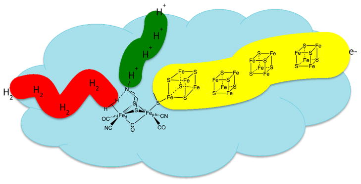
Structure of the active site of the [FeFe] hydrogenase with simplified depiction of the associated connectivity for electron, hydrogen, and proton transport.

The cyanide and CO ligands in the active sites of hydrogenases are unusual for metalloenzymes. These ligands form strong bonds to transition metals in lower oxidation states, resulting in the formation of low-spin complexes. This feature is advantageous, because low-spin complexes interact most readily with H2 to form hydride intermediates.7 Thus, nature’s use of CN and CO ligands in the active site of the hydrogenase can be understood in terms of ligand field effects familiar to inorganic chemists. These structural studies of the active sites of [FeFe] and [NiFe] hydrogenases have led the synthetic chemist to try to reproduce the ligand coordination set of these enzymes in organometallic complexes, and a large number of complexes containing CO, CN, and other strong field ligands such as phosphines and carbenes have been synthesized and evaluated for their catalytic activity. In general, these complexes exhibit catalytic activity for H2 production, but only at very negative potentials, and their rates are slow as compared to those of the enzymes. However, these studies provide a useful baseline from which to assess structure/activity relationships.
An interesting structural feature of the active site of the [FeFe] hydrogenase is the presence of a three-atom bridge spanning the two bridging S atoms. It has been proposed that the two sulfur and three atom bridge is the 2-azapropane-1,3-dithiolate ligand,8 and the identity of the central atom of the dithiolate ligand as an N atom has been supported by spectroscopic studies.9 The pendant amine of the azadithiolate ligand is positioned close to the distal Fe atom (Fed). This pendant amine is ideally placed to assist in the heterolytic cleavage of H2 by acting as a base, while the vacant coordination site on Fe acts as a Lewis acid. Because of the reversibility of this enzyme, the Lewis acidity or hydride acceptor ability of the Fe center and the proton acceptor ability of the pendant amine must be closely matched so that the free energy for H2 addition to (or release from) the active site is nearly zero. In addition to assisting in the reversible heterolytic cleavage and formation of the H–H bond, the pendant amine is also thought to assist in the transfer of protons between the active site and a proton conduction channel that leads to the exterior of the enzyme.5a,10
The interpretation of the structure–activity relationships outlined in the preceding paragraphs has been supported and enhanced by studies of synthetic organometallic mimics.11 The diiron subunit of the six-iron H-cluster in [FeFe] hydrogenase, 1, exhibits structural features that are reminiscent of the classic propanedithiolate FeIFeI organometallic complex, (pdt)[Fe-(CO)3]2 (pdt = propane dithiolate, –S(CH2)3S–), 4.12 However, in the crystal structure of the enzyme, the active site is thought to be in a mixed-valent FeIFeII oxidation state, and significant differences exist between structures 1 and 4. Of most importance is the presence of a vacant coordination site on the distal Fe atom adjacent to the azadithiolate bridge. This so-called entatic state or rotated structure has been observed for oxidized analogues of 4 in which CO ligands have been replaced with electron-rich phosphine or carbene ligands to stabilize the oxidized states.13 In the enzyme, the juxtaposition of the azadithiolate ligand and the vacant coordination site is stabilized by the presence of hydrogen bonds between the cyanide ligands and the protein. These hydrogen-bonding interactions also likely stabilize this geometry in the reduced form of the enzyme.
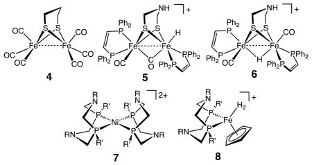
The kinetic product of protonation of diiron(I) dithiolates is a terminal hydride such as 5. For diiron complexes with a bridging dithiolate ligand, the pendant N atom of the azadithiolate complex plays an important role in exchange reactions between acids and bases in solution and terminal hydride ligands. In these exchange reactions, the positioning of the hydride ligand adjacent to the pendant amine is required for both proton/hydride exchange and for catalytic production and oxidation of H2.10,13a,14 Isomerization of the terminal hydride to the thermodynamically more stable bridging hydride 6 results in the cessation of proton/hydride exchange and catalysis.
The concept of a pendant amine adjacent to a vacant coordination site or hydride ligand has been extended to the development of electrocatalysts for the oxidation and production of H2 using simple mononuclear complexes of Ni, Co, and Fe with diphosphine ligands containing positioned pendant amines as opposed to an azadithiolate ligand, for example, 7 and 8.15 Thus, the principles used by [FeFe] hydrogenases, the use of ligands with strong ligand fields, positioning of a pendant base in close proximity to a vacant coordination site, and energy matching of hydride donor/acceptor abilities of the metal with proton/donor–acceptor abilities of the pendant acid/base, appear to be broadly applicable to the design and development of electrocatalysts for H2 oxidation and production based on a variety of inexpensive metals.
To this point, we have discussed primarily the roles of the first and second coordination spheres and their influence on catalytic activity in both enzymes and molecular catalysts, where the first coordination sphere is considered to be composed of those ligands immediately bound to the metal center and the second coordination sphere is defined as functional groups that can interact with substrates bound to the metal, but only weakly or not at all with the metal center itself. An additional feature, present in the enzymes and only beginning to be probed in synthetic catalysts, is the role of the outer coordination sphere, which is defined as that portion of the enzyme or metal complex not in the first or second coordination spheres. As discussed above, hydrogen bonding between the N atoms of the cyanide ligands and the protein may play an important role in controlling the structure of the active site. The protein can also influence the local environment by providing hydrophobic or hydrophilic contacts at precise locations and creating an environment with an optimal dielectric constant. Perhaps most interesting is the presence of molecular wires consisting of Fe4S4 clusters, proton conduction channels, and hydrophobic tunnels thought to facilitate H2 movement through the protein matrix. These structural features, illustrated schematically in Figure 1, result in the precise delivery of substrates (protons, electrons, dihydrogen) to and removal of products from the active site. Because of these features, the hydrogenases are essentially half of a hydrogen fuel cell or electrolysis unit on the molecular scale. This high degree of control in molecular catalysis has not been achieved, but initial steps including the attachment of redox-active units to mimic the Fe4S4 clusters and secondary proton relays have been reported.16
The rapid progress described above in understanding the relationship between structure and function in hydrogenases and in their mimics is the result of synergistic interactions between the catalytic inorganic chemists, structural scientists, spectroscopists, microbiologists, and biochemists. This understanding has resulted in significant advances in the development of new classes of simple molecular catalysts for H2 production and oxidation. It is this type of constructive synergy that we hope will emerge in the development of new concepts that are applicable to the design of new catalysts for CO2 reduction to a variety of fuels.
3. OVERVIEW OF THE BASIC CHEMISTRY AND BIOLOGY OF CO2
3.1. Chemistry of CO2
Carbon dioxide is a linear molecule with a very short C–O distance of 1.16 Å. Although overall nonpolar, CO2 contains polar bonds due to the difference in electronegativity between C and O. Its electronic structure is best represented as O−δ–C+2δ–O−δ, highlighting its susceptibility to nucleophilic attack at carbon and electrophilic attack at oxygen, often discussed in terms of its quadrupole moment.17 With an ionization potential of 13.78 eV (vs 12.6 for water, 10.0 for ammonia), CO2 is nonbasic and interacts only weakly with Bronsted and Lewis acids. With a carbon-localized LUMO, CO2 is susceptible to attack by nucleophiles and to reduction.
The first step in the reduction of CO2 involves “activation of CO2”, that is, a decrease of the C–O bond orders. Activation is manifested mostly in the bending of the molecule. Bent CO2 interacts with electrophiles and nucleophiles through its frontier orbitals (Figure 2).
Figure 2.
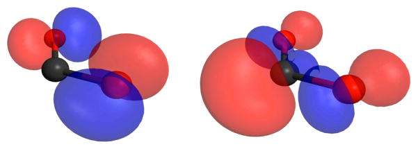
Wave function iso-probability contours for the highest occupied molecular orbital (HOMO) (left side panel) and lowest unoccupied molecular orbital (LUMO) (right side panel) of bent CO2. The surfaces illustrate the strong charge localization associated with these frontier orbitals.
The lowest unoccupied molecular orbital (LUMO) exhibits strongly localized wave function probabilities, enhancing the interaction with nucleophiles by facilitating the transfer of electron density from the nucleophile into the LUMO. The highest occupied molecular orbital (HOMO) with its strongly localized electron density as oxygen in-plane lone pairs is conducive to interactions with electrophiles. The energetic penalty associated with activating CO2 is reflected in the very negative potential for its one electron reduction (see below). Correspondingly, in its bent form, CO2 is predisposed to undergo two electron reduction rather than one. Reactions of CO2 in biological systems tend to be supported by a combination of nucleophilic and electrophilic interactions, a principle that is increasingly embraced in chemical systems (eq 1). In the absence of these combined interactions, powerful electrophiles or nucleophiles are required.
 |
(1) |
The energetic requirements for CO2 reduction are highly sensitive to pH and the number of electrons (eqs 2–7) for the half-reactions as shown below for pH 7 vs NHE. Recall that at pH 7 and 1 atm of H2, the H2/H+ couple is −0.420 V.
| (2) |
| (3) |
| (4) |
| (5) |
| (6) |
| (7) |
One-electron reduction of CO2 (eq 2) occurs at very negative potentials, due in part to the energy required for the large structural rearrangement from linear CO2 to bent CO2−•.18 However, the coupled multielectron and multiproton reactions occur at relatively modest potentials (eqs 3–7). As they involve protons, reactions 3–7 are more favorable at low pH.19 These reactions are also highly solvent dependent. As found for the [FeFe] and [NiFe] hydrogenases, redox-active metal centers endowed with proton relay sites in their second coordination spheres are well suited to promote these proton-assisted multielectron transfer reactions.
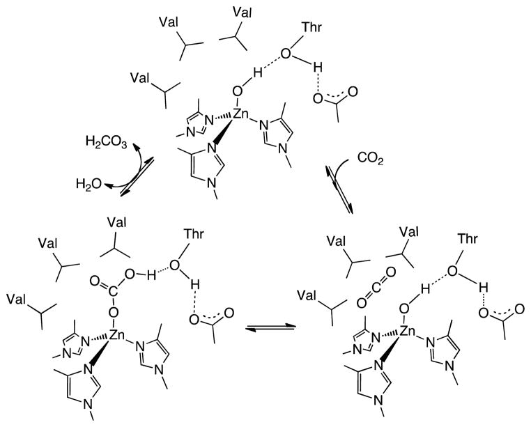
Relative to other typical gases (H2, N2, O2), CO2 is highly soluble in water. The equilibrium constant between dissolved CO2 and gaseous CO2 above the solution (Henry constant) is 29.76 atm/(mol/L) at 25 °C (i.e., 0.033 M at 25 °C under 1 atm CO2). In water, an equilibrium is established with carbonic acid, H2CO3. The equilibrium constant for hydration at 25 °C, [H2CO3]/[CO2], is low at 1.70 × 10⁻³. In the absence of a catalyst, equilibrium is achieved only slowly. The rate constants are 0.039 s−1 for the forward reaction (CO2 + H2O → H2CO3) and 23 s−1 for the reverse reaction (H2CO3 → CO2 + H2O). H2CO3 is a weak diprotic acid with pKa1 = 3.6 at 25 °C, about 10× stronger than typical carboxylic acids. In many reports, the pKa1 is calculated to include dissolved CO2, which results in a lower apparent pKa1 = 6.3 at 25 °C. The second constant for the dissociation of the bicarbonate ion into the carbonate ion CO32− is characterized by pKa2 = 10.329 at 25 °C (all pK at ionic strength = 0.0). With atmospheric CO2 approaching 400 ppm, the concentrations in water at 25 °C are calculated to be 1.2 × 10⁻⁵ M for CO2, 2 × 10⁻⁸ M for H2CO3, 2.3 × 10⁻⁶ M for HCO3−, and 10−5.6 M for protons (pH = 5.6) at 25 °C. These equilibria are relevant to the threat of ocean acidification considering that the average pH of the oceans is presently near 8.1.1
3.2. Biology of CO2
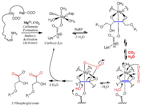
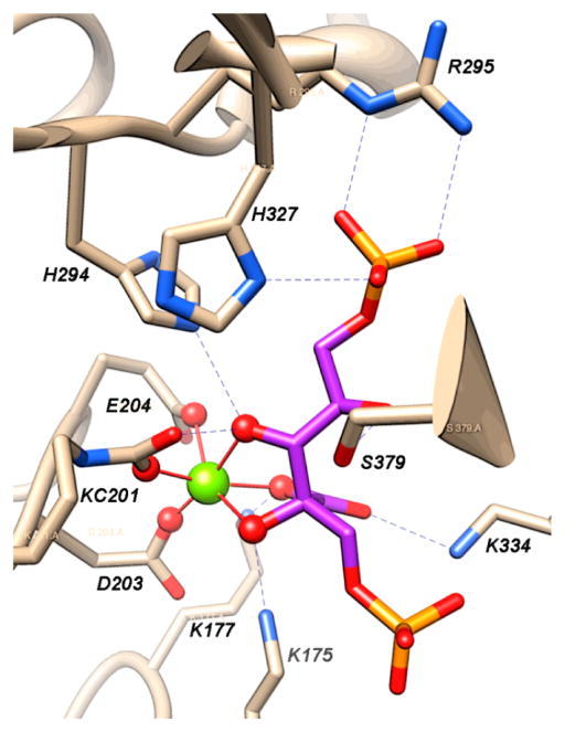
Six pathways are known for the fixation of inorganic carbon into organic material used for cell biomass.20 The reductive pentose phosphate (Calvin–Benson–Bassham) cycle20,21 is the predominant mechanism by which many prokaryotes and all plants fix CO2 into biomass. This reaction begins with the ribulose bisphosphate carboxylase/oxygenase (RuBisCO)-catalyzed carboxylation of the five-carbon sugar 1,5-ribulose bisphosphate to form two molecules of 3-phosphoglycerate,22 which undergoes a series of interconversions to form the six-carbon sugar fructose-1,6-bisphosphate. The substrate 1,5-ribulose bisphosphate is regenerated in the process. The net reaction catalyzed by the various enzymes in the Calvin cycle is given in eq 8.
| (8) |
The net reaction for four of the other five CO2-fixation pathways is: 8H+ + 8e− + 2CO2 + HSCoA → acetyl-CoA + 3H2O. Among these pathways, the reductive acetyl-CoA pathway (Wood–Ljungdahl pathway)23 is covered in greatest detail in this Review. This pathway is used by bacteria and methanogenic archaea to synthesize acetyl-CoA from CO2 for anabolic (biosynthesis) and catabolic (energy) purposes.23,24 This pathway contains two CO2 reduction steps: the formate dehydrogenase-catalyzed reduction of CO2 to formate and CO dehydrogenase-catalyzed reduction of CO2 to CO.
Another autotrophic pathway is the reductive citric acid cycle (also known as the reductive TCA and Arnon–Buchanan cycle), which has the same net equation as that describing the Wood–Ljungdahl pathway. It is mostly a reversal of the citric acid cycle, generating acetyl-CoA from two CO2; however, there are some modifications to circumvent the irreversible steps in the oxidative pathway.25 The four carboxylation steps in the reverse TCA cycle are catalyzed by 2-oxoglutarate synthase (CO2 + succinyl-CoA + reduced ferredoxin → 2-oxoglutarate + HSCoA + oxidized ferredoxin), nondecarboxylating isocitrate dehydrogenase (HCO3− + ATP + NADH + 2-oxoglutarate → isocitrate + ADP + Pi + NAD), pyruvate ferredoxin oxidoreductase (also known as pyruvate synthase when run in this direction: CO2 + acetyl-CoA + reduced ferredoxin → pyruvate + CoA + oxidized ferredoxin), and phosphoenolpyruvate synthetase (HCO3− + phosphoenolpyruvate → oxaloacetate + Pi).
The dicarboxylate/4-hydroxybutyrate cycle20 involves, in one stage, the seven-step conversion of acetyl-CoA, CO2, and bicarbonate through four-carbon dicarboxylic acids to succinyl-CoA, which undergoes the seven-step conversion to two molecules of acetyl-CoA. The carboxylation steps occur in the first stage and are catalyzed by pyruvate synthase and phosphoenolpyruvate carboxylase.
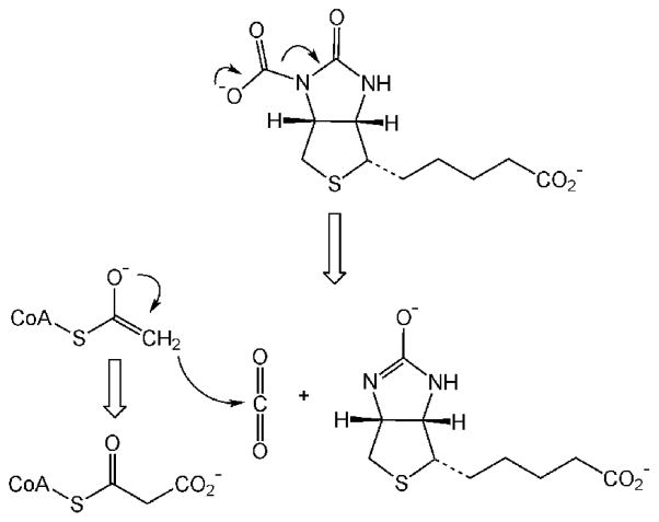
The 3-hydroxypropionate/4-hydroxybutryate cycle20 is very similar to the dicarboxylate/4-hydroxybutyrate cycle in that it shares the seven-step conversion of succinyl-CoA to two molecules of acetyl-CoA. The difference is in how succinyl-CoA is regenerated from acetyl-CoA. In this cycle, succinyl-CoA is regenerated by the nine-step conversion of acetyl-CoA and two molecules of bicarbonate to succinyl-CoA. The two carboxylation reactions involved in the conversion of acetyl-CoA to succinyl-CoA in the 3-hydroxypropionate cycle are catalyzed by acetyl-CoA carboxylase (acetyl-CoA + HCO3− + ATP → malonyl-CoA + ADP + Pi) and propionyl-CoA carboxylase (propionyl-CoA + HCO3− + ATP→ methylmalonyl-CoA + ADP + Pi).
The 3-hydroxypropionate bicycle20 is so-named bicycle because one cycle involves carboxylation of propionyl-CoA followed by the seven-step conversion of methyl-malonyl-CoA to glyoxylate and acetyl-CoA. The carboxylation step is catalyzed by propionyl-CoA carboxylase (propionyl-CoA + ATP + HCO3− → methylmalonyl-CoA + ADP + Pi). The other cycle involves the condensation of gloxylate (formed in the first cycle) with propionyl-CoA to generate methylmalyl-CoA, which is converted in four steps to pyruvate and acetyl-CoA. To regenerate propionyl-CoA, the acetyl-CoA that was formed in the two cycles undergoes carboxylation in a reaction catalyzed by acetyl-CoA carboxylase (ATP + acetyl-CoA + HCO3− → malonyl-CoA + ADP + Pi) to form malonyl-CoA, which undergoes two two-electron reduction steps to form hydroxypropionate and finally propionyl-CoA. The net equation for this bicycle is given in eq 9.
| (9) |
Here, we have described these six CO2 fixation pathways and highlighted the enzymes and reactions involved in the carboxylation of various sugars, CoA esters, and carboxylic acids and in the reduction of CO2 (to CO and formate). There are numerous other enzymatic CO2 reduction reactions, some of which are also covered in this Review. Two examples include methanogenesis, which involves the eight-electron reduction of CO2 to methane,26 and the folate-dependent one-carbon pathway, which involves the conversion of CO2 to methyltetrahydrofolate, a key component of the Wood–Ljungdahl pathway and the biosynthesis of methionine.
4. BIOLOGICAL AND CHEMICAL REDUCTION OF CO2 TO CARBON MONOXIDE (CO) OR FORMATE (HCOO−)
4.1. Overview
Enzymes have been identified that catalyze the reversible reduction of CO2 to CO (CO dehydrogenases) or CO2 to formate (formate dehydrogenases). X-ray diffraction studies of both classes have been reported at sufficiently high resolution to provide useful structural information about the nature of the active site. In the following discussion, a structural/mechanistic approach will be used to highlight similarities and differences between enzymes and synthetic catalysts. As with the hydrogenases, we will attempt to understand the roles of the first, second, and outer coordination spheres in the overall catalytic process. The CO dehydrogenases and synthetic catalysts for CO2 reduction will be discussed first, followed by formate dehydrogenases and their synthetic analogues. One of the interesting issues to consider is how the two types of enzymes control the binding of CO2 and the transfer of electrons and protons to partition intermediates on the reduction pathway toward CO or its hydrated analogue, formate.
Both formic acid and CO contain “divalent carbon”. Formic acid can be dehydrated to CO, and through the reverse reaction, CO can be converted to formate in the presence of hydroxide. In some chemical syntheses, formic acid can be used as a surrogate for CO, for example, in the Koch formylation of arenes.27 Industrially, formic acid is not produced by reduction of CO2 but instead by the carbonylation of methanol followed by the hydrolysis of the resulting methyl formate.28
4.2. CO Dehydrogenases
There are two types of CO dehydrogenases (CODHs), enzymes that catalyze the reduction of CO2 to CO. The first of these is the O2-sensitive enzyme from obligate anaerobes such as Moorella thermoacetica, Carboxydothermus hydrogenoformans, and Methanosarcina barkerii with [Fe4S4Ni] active sites. These enzymes exhibit turnover frequencies for CO oxidation as high as 40 000 s−1 (at 70 °C using methyl viologen cation as oxidant) and 45 s−1 for CO2 reduction. These enzymes also operate at potentials near the thermodynamic potential of the CO2/CO couple, −0.52 V vs the SHE at pH 7.29 Air-stable [MoSCu]-containing enzymes comprise the second class of CODHs. These occur in aerobes such as Oligotropha carboxidovorans. These enzymes exhibit lower turnover frequencies, for example, 100 s−1 for CO oxidation.30 The Cu–Mo CODHs do not catalyze the reduction of CO2 to CO, probably because the copper(I) center is insufficiently reducing. Both enzymes contain bimetallic active sites, featuring metal centers that are both soft (Ni, CuI) and hard (high-spin FeII, MoIV/VI). Because of the different metals at their active sites, it is expected that the mechanisms of CO oxidation for these two classes differ, and the differences and similarities of these enzymes and of their synthetic models are discussed in more detail below.
4.2.1. [NiFe] CO Dehydrogenases
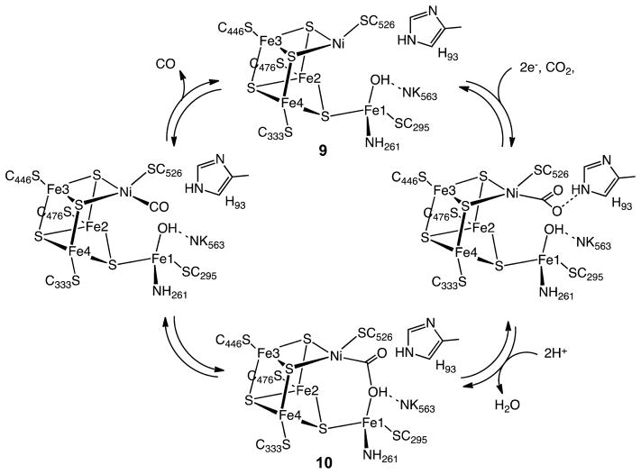
Of special importance to our understanding of the catalytic mechanism of CO2 reduction of the [NiFe] CODHs has been a series of spectroscopic and structural studies of the oxidized and reduced forms of the enzyme with different substrates and inhibitors. The active site of the oxidized enzyme, which is shown in Figure 3 and schematically by structure 9 in Scheme 1, consists of Ni and Fe centers bridged by an Fe3S4 cluster that rigidly positions these two metal centers in close proximity.31 In this state, a coordinatively unsaturated NiII species binds three S ligands in an apparent planar T-shaped environment, which is unusual in synthetic compounds, and may suggest the presence of a hydride ligand.32 The first coordination sphere of the Fe1 center consists of a histidine ligand (H261), a cysteine (C295), a μ3-sulfido ligand, and a fourth light atom, possibly water/hydroxide. This fourth ligand is also in close proximity (2.7 Å) to Ni.31a The close proximity of the Ni and Fe atoms and the apparent vacant coordination site on Ni suggests the likelihood of cooperative interactions between the two metal centers during catalysis, an expectation borne out by the structure of the CO2-bound form of the enzyme.
Figure 3.
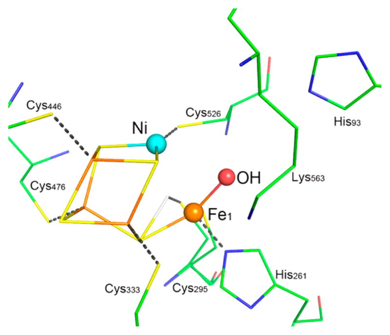
Ball-and-stick drawing of the active site of [NiFe] CO dehydrogenase.
Scheme 1. Proposed Mechanism for the Reduction of CO2 to CO by [NiFe] CODH.
X-ray diffraction studies of crystals treated with bicarbonate ion and a reducing agent, TiIII citrate, revealed an active site, 10, that is nearly identical to structure 9, with the exception of three light atoms bridging the Ni and Fe atoms.31a These three atoms have been modeled as a bridging CO2 molecule. In addition, NMR studies of a CO/CO2 exchange reaction provide evidence both for the involvement of a CO2 binding site and for an internal proton transfer network in catalysis by CODH.33 On the basis of the crystal structure, CO2 binds to Ni via the C atom to form a Ni–C bond (1.96 Å) and with one of the carboxylate oxygen atoms (O1) bound to Fe1 (Fe1–O1 distance of 2.05 Å), as well as forming a hydrogen bond to a lysine residue (K563).31a The second (exocyclic) oxygen atom, O2, appears to be hydrogen bonded with a protonated histidine residue (H93). Thus, CO2 binding and catalysis in the enzyme appears to involve bifunctional activation by the two metal centers and additional stabilization from appropriately positioned residues in the second coordination sphere. This activation pathway is reminiscent of the “frustrated Lewis acid–base pair” motif whereby simple Lewis acids and bases cooperate in binding CO2, for example, formation of R3B–O–C(O)–PR3.34 It is also similar in many respects to the binding and heterolytic activation of H2 by hydrogenase enzymes and synthetic catalysts with pendant amines, which also involve frustrated Lewis acid–base pairs.
Further information on possible modes of interaction of the active site with CO2 has been provided by biochemical experiments and X-ray diffraction studies of crystals of the enzyme inhibited by n-butyl isocyanate (BuNCO). This species (structure 11) was obtained by treating CODH with n-butyl isonitrile.35 The Ni is bound to the isocyanate ligand via a C atom, but the isocyanate ligand does not interact with Fe. Ni adopts a distorted tetrahedral geometry as opposed to the distorted square-planar geometry observed in the CO2 adduct. The Ni–C bond length (1.95 Å) is essentially the same as that observed for the CO2 adduct (10). An elongated Ni–Fe1 distance of 3.10 Å is observed, indicating that this linkage is somewhat flexible. Histidine 93 (H93) and the hydroxide/water molecule bound to Fe1 are hydrogen bonded to the oxygen atom of the isocyanate ligand, stabilizing the interaction between this CO2 analogue and Ni. This observation suggests that H93 toggles between the two oxygen atoms of CO2 during the catalytic cycle as Ni is oxidized or reduced and water or hydroxide coordinates or dissociates. The isocyanate complex is proposed to mimic an intermediate in the catalytic cycle prior to formation of the Ni–O–C–O–Fe bridge in CO2 reduction.
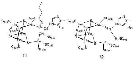
Spectroscopic and kinetic studies indicate that cyanide, which is isoelectronic with CO, is a slow-binding inhibitor that binds to CODH to form at least two separate complexes.36 Crystallographic results on the cyanide adduct of the [NiFe] CODH are consistent with biochemical studies. Two slightly different structures were found, one with a linear37 and a second with a bent NiCN centers.38 In the latter structure, there is a water/hydroxide ligand bound to Fe1 with a possible hydrogen bond between the N atom of the CN ligand and water or hydroxide, while in the former, shown in structure 12, the water/hydroxide is absent. The NiCN center is proposed to resemble the NiCO center prior to its undergoing nucleophilic attack by the Fe-bound hydroxide to form the nickelacarboxylate (NiCO2−) described above.
On the basis of these kinetic, spectroscopic, and structural studies, the mechanism shown in Scheme 1 can be proposed for CO2 reduction by [NiFe] CODH. An overall two-electron process likely occurs via an ECE mechanism: an electron transfer step (E) to form NiI, followed by a chemical step (C) involving binding of CO2 to the reduced nickel center, and finally a second electron transfer step (E). Other pathways may also be possible, but regardless of the precise sequence, the resulting CO2 adduct is stabilized by hydrogen-bonding interactions with a protonated histidine residue as shown for the isocyanate structure 11. Loss of water from Fe1 results in the formation of a CO2 complex 10, in which one oxygen of the CO2 molecule, O1, is bound to Fe1 and is hydrogen bonding with a protonated lysine residue K563. Cleavage of the C–O1 bond and loss of water results in the formation of a NiIICO species that is analogous to the cyanide structure, 12. This NiII CO species readily loses CO and adds water to regenerate the starting NiII complex and complete the catalytic cycle.
4.2.2. Studies of Metal Electrocatalysts Relevant to [NiFe] CO Dehydrogenases
Since the 1980s, CoI and NiI macrocyclic complexes of ligands 13–16 (Chart 1) have been examined in some detail as electrocatalysts for CO2 reduction,39 and a number of reviews describe this chemistry.15a,39,40 The participation of CoI and NiI centers is distinctive as they are strong one-electron reductants. The CO2 binding constants span a large range, from less than 1 to 108 M−1,40a,41 and both the binding constants and the second-order rate constants largely correlate with the MII/I reduction potentials in organic solvents. Solvent effects can be large,40a,41b and water exerts an especially large effect, which may be due to hydrogen bonding to the CO2 ligand.
Chart 1.

In addition to this intermolecular hydrogen bonding, intramolecular hydrogen bonding to ligand NH protons has been demonstrated for a Co–CO2 adduct, 17, where the CoI center donates two electrons to the bound CO2 to form a CoIII-carboxylate.41a,42 In nonpolar solvents such as tetrahydrofuran (THF), ion pairing is important.43 For example, the binding constant of [Co(7,7′-dimethylsalen)]−1 for CO2 in THF is over 100 times larger when NaCF3SO3 is the supporting electrolyte as compared to [Bu4N]CF3SO3.41b These observations indicate that the binding of CO2 is controlled by a combination of inner sphere (redox potential, nucleophilicity) and secondary interactions (hydrogen bonding, ion pairing). The stabilizing effects of hydrogen bonding and ionic interactions observed for these discrete complexes are similar to the hydrogen-bonding interactions inferred for the active sites of [NiFe] CO dehydrogenases.
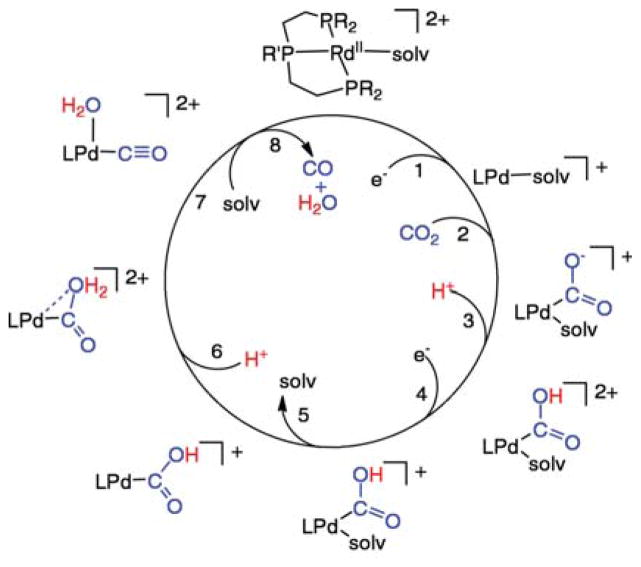
Highly active molecular electrocatalysts for reduction of CO2 to CO are the complexes [Pd(triphosphine)(solvent)]2+ shown in Scheme 2 (triphosphine = RP(CH2CH2PR′2)2, where R and R′ can be aryl or alkyl substituents).44 The catalytic mechanism shown has been studied in detail, and it illustrates important steps that are common to many catalysts known to reduce CO2 to CO, as well as some unique features that are also present in the [NiFe] CODH enzymes. To simplify discussion of this catalytic cycle, four critical steps are emphasized: electron transfer to reduce PdII, CO2 binding to the PdI center, C–O bond cleavage with a formal loss of O2−, and dissociation of CO.
Scheme 2. Proposed Mechanism for the Reduction of CO2 to CO Catalyzed by [Pd(triphosphine)(solvent)]2+ Complexes.
4.2.2.1. Electron Transfer
In the process of reducing CO2 to CO, two electrons must be transferred. In Scheme 2, one electron transfer occurs immediately before CO2 binding, and the second electron transfer occurs two steps later, after protonation of the bound CO2. Clearly the two electron transfer steps are not concerted, but are regulated or gated by intervening chemical steps. The intervention of chemical steps between electron transfer steps is a general observation for electrocatalyzed reductions of CO2. Because of this gating mechanism, concerted two-electron reductions of the metal center are not required for efficient catalysis.
4.2.2.2. CO2 Binding in Monofunctional Catalysts
In Scheme 2, the reduction of PdII to PdI (step 1) is immediately followed by CO2 binding (step 2) to form a metal carboxylate complex, M–CO2. For the Pd(triphosphine)(solvent)]2+ catalysts shown in Scheme 2, the reaction of PdI with CO2 is the rate-determining step at high acid concentrations (greater than 0.01 M) with second-order rate constants ranging from 5 to 300 M−1 s−1 corresponding to catalytic turnover frequencies of 1–60 s−1 under 1.0 atm of CO2 in acetonitrile or dimethylformamide.44a,e As with the NiI and CoI complexes discussed above, the rate constants for the reaction of the PdI intermediates with CO2 are dependent on the potential of the PdII/I couple, and a linear dependence is observed between ln(k) and E1/2(II/I).44c The first two steps in Scheme 2, electron-transfer and CO2 binding, are also common to macrocyclic Fe, Co, and Ni catalysts. One-electron reductions are followed by reaction with CO2.39b,45 However, for these Fe, Co, and Ni macrocycles, which operate at much more negative potentials than the Pd phosphine complexes, the rate-determining step is not the reaction of CO2 with the reduced metal species. For example, the rate of reaction of CoI(rac-L) (L = 16) with CO2 is 1.7 × 10⁸ M−1 s−1,41a but the overall catalytic rates are on the order of a few turnovers s−1. Similarly, the reduced Fe tetraphenylporphyrin complexes react very rapidly with CO2, but generation of the reduced forms of these catalysts requires very negative potentials. CO2 binding is not generally the rate-determining step for catalysts reduced at very negative potentials.45a–c,e–h However, for catalysts operating at more positive potentials (lower overpotentials) such as the Pd catalysts shown in Scheme 2, CO2 binding can become rate limiting.
4.2.2.3. C–O Bond Cleavage (Oxide Transfer)
Once CO2 has added to the reduced metal complex, C–O bond cleavage must occur to form CO, as observed in Scheme 1 for [NiFe] CODH. This fundamental reaction was shown to occur stoichiometrically upon reaction of reduced complexes of CO2 with even weak proton donors. In a classic example, treatment of Ni(η2-CO2)(P(C6H11)3)2 with H2S gives CO complexes.62,46 This process normally begins with O-protonation of the bound CO2 molecule to form a metallocarboxylic acid47 (step 3 of Scheme 2). Alternatively, metal carboxylates can also interact with a Lewis acid such as Na+ or Mg2+, or even a second molecule of CO2.45f–h For the cobalt and nickel macrocyclic catalysts, CO2 is the ultimate oxide acceptor resulting in carbonate salts and CO formation. The C–O bond cleavage may be the rate-determining step for some of these macrocylic Co and Ni catalysts.45d,48
For the [Pd(triphosphine)(solvent)]2+ complexes shown in Scheme 2, the metallocarboxylic acid formed in step 3 does not spontaneously undergo C–O bond cleavage. Before C–O bond cleavage can be achieved, an additional electron transfer (step 4), solvent dissociation (step 5), and a second protonation (step 6) are required. In this reaction sequence, the loss of a weakly coordinated solvent molecule (step 5) is critical. This produces a vacant site on the metal for water to occupy as the C–O bond is broken to form coordinated CO and water (step 7).44b This C–O bond cleavage reaction is the rate-determining step for these catalysts at low acid concentrations, as it is for Fe(porphyrin) catalysts at low acid concentrations (H+, Mg2+, or CO2). 45f–h In the Fe porphyrin case, catalysis occurs at approximately −2.0 V vs the ferricenium/ferrocene couple, much more negative than those of the [Pd(triphosphine)(solvent)]2+ complexes (−1.1 to −1.4 V). This more negative potential facilitates the loss of water (or carbonate) and cleavage of the C–O bond for the Fe catalysts. In the Fe porphyrin case, a vacant coordination site is not required to achieve high catalytic rates, but large overpotentials are observed as a result. The role of a vacant coordination site for C–O bond cleavage for the Pd catalysts suggests that similar vacant coordination sites on Ni and Fe for the [NiFe] CODH active site, 9, are important for facile C–O bond cleavage by the enzyme.
4.2.2.4. M–CO Bond Cleavage
Once the C–O bond has been cleaved, completion of the catalytic cycle requires CO dissociation. Cleavage of the M–CO bond of the metal carbonyl complex is rapid for both [Pd(triphosphine)-(solvent)]2+ and Fe porphyrin catalysts. For the palladium system, the PdII and PdI species formed during the catalytic cycle have little affinity for CO.44a,b For the iron porphyrin system, CO is rapidly expelled upon reduction of the ferrous center.45f–h Studies of Co(salophen) catalysts suggest that the loss of CO is a possible rate-determining step.45d It has been shown that a [CoI(salophen)(CO)]− complex is formed during the catalytic cycle, and that the release of CO from these complexes is slow. For [CoI(rac-Me6[14]4,11-diene)(CO)]+, the rate of CO loss has been reported to be 3 s−1 in water.48 For these cobalt complexes, either the cleavage of the Co–C bond or the cleavage of the C–O bond may be the rate-determining step, but the slow loss of CO provides an upper limit to the rate at which these catalysts can operate.
4.2.2.5. Bifunctional Binding and Activation of CO2
The rate-limiting step for catalysis by the [Pd(triphosphine)-(MeCN)]2+ complexes under normal operating conditions is the binding of CO2. To facilitate formation of the CO2 adduct, complex 18 was designed to interact with CO2 in a bifunctional manner.44d In this bimetallic complex, one Pd atom is proposed to bind the carbon atom of CO2, and a second Pd binds one of the oxygen centers as shown by structure 19 (eq 10). Complex 18 shows high catalytic rates (k > 104 M−1 s−1) for CO2 reduction to CO, and it shares some interesting structural features with the [NiFe] CODH 9 and the reduced form plus CO2 10. These include vacant coordination sites on both metals that may be important for C–O bond cleavage and two positioned sites for bifunctional binding of CO2. Although very fast, catalyst 18 exhibits only a few turnovers before it is deactivated. Deactivation is thought to arise by formation of a Pd–Pd bond, a reaction that is less likely for first row metals. In addition, the different redox potentials of the Fe and Ni sites in [NiFe] CODH would prevent M–M bond formation as the Fe will not be reduced at potentials that reduce Ni.
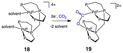 |
(10) |
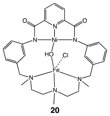
The structural similarities of the [PdPd] catalytic intermediates 18 and 19 with intermediates 9 and 10 of [NiFe] CODH suggest that the structural features could guide the development of synthetic catalysts based on inexpensive metals. An interesting step in this direction is a macrocyclic Fe–Ni complex 20, where the two metals are closely positioned in a way that could stabilize CO2 binding. Unfortunately, no catalytic activity for CO2 reduction was reported for this complex.49
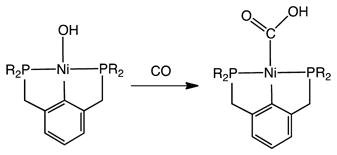
The formation of relevant Ni-CO2H derivatives has been described, but via an CO + Ni–OH pathway (eq 11),50 not via CO2 + Ni–H pathway, which typically affords formates.51
 |
(11) |
An iron porphyrin complex with a hydroxyl functional group in the second coordination sphere has been reported to catalyze the electrochemical reduction of CO2 to CO in acidic dimethylformamide solutions with moderate overpotentials. In this case, the reduced Fe center may serve as a nucleophile, while the proton of the pendant hydroxyl group serves as an proton donor to assist the cleavage of the C–O bond.52
4.2.3. [MoCu] CO Dehydrogenases
The second class of CODHs features a unique Mo–Cu active site. The main structural features of the oxidized and reduced forms of the active site based on X-ray diffraction studies are depicted by structures 21 and 22,30b and of the active site in the presence of n-butylisonitrile by structure 23 (Chart 2).30b The active site of oxidized [MoCu] CODH, 21, contains a dinuclear [CuSMo(=O)OH] metal center with a copper ion bridged via a sulfide ligand to a molybdenum oxo group. The Mo atom exhibits a distorted square pyramidal geometry with the oxo group in the apical position. In addition to the bridging S atom, two sulfur atoms of the molybdopterin cytosine dinucleotide cofactor coordinate to the Mo ion. A hydroxo group is thought to complete the coordination sphere. The second coordination sphere of Mo contains several residues that are within hydrogen-bonding distances of the oxo and hydroxo ligands. The CuI ion exhibits a linear two-coordinate geometry with a second sulfur atom from a cysteine residue completing its first coordination sphere. The reduced form of the active site retains the same overall geometry, but with a lengthening of the Cu–Mo distance and the Mo–O bond distances to the oxo and hydroxy ligands.
Chart 2.

Structures of the Oxidized (21) and Reduced (22) States of the [MoCu]–CODH and a n-Butylisocyanide Inhibited Form (23)
In the n-butylisonitrile-inhibited enzyme, the C atom of the isonitrile has inserted into the Cu–S bond concomitant with formation of a C–O bond to the terminal OH ligand. The insertion of the RNC group into the Cu–S bond results in an increase in the Cu---Mo distance from 3.74 to 5.07 Å. The N atom of isonitrile is bound to Cu, which remains in a linear coordination environment, ligated to the N atom of n-butylisonitrile and the S atom of Cys-388. Studies on the n-BuNC-inhibited enzyme point to the mechanism A (shown on the left of Scheme 3) for the CO oxidation pathway. In this scheme, the reaction of a MoVI oxo/hydroxy species with CO leads to the formation of the reduced MoIV state with a thiocarbonate insertion product analogous to that observed for the isonitrile adduct 23. This thiocarbonate intermediate then loses CO2 to regenerate the reduced form of the active site, a MoIV species (22). Oxidation of 22 by two electrons regenerates the oxidized form of the active site 21.
Scheme 3. Proposed Mechanisms for the Oxidation of CO to CO2 by [MoCu] CODHa.
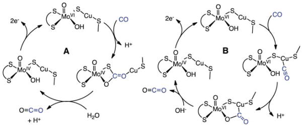
aA: Mechanism implicated by the structure of the n-BuNC-inhibited enzyme. B: Mechanism involving CO coordination to Cu and attack of Mo–O(H) on C atom of carbonyl.
Some caution must be exercised regarding this mechanism, because it is possible that the n-BuNC derivative is simply a thermodynamic trap that is not relevant to the CO/CO2 interconversion. It is well-known that CuI species form adducts with CO, and the stretching frequencies, νCO, for such adducts are generally high, often near 2100 cm−1.53 This suggests the possibility of mechanism B (shown on the right in Scheme 3) in which CO coordinates to copper followed by nucleophilic attack of a Mo–OH group on the Cu–CO center. This alternate mechanism has been proposed for MoCu–CODH,54 based on theoretical calculations, and would entail less structural change of the Mo–S–Cu subunit during catalysis. An interesting feature of either mechanism is that, although Mo undergoes a change in oxidation state, unlike Ni in the [NiFe] CODH, Mo does not bind CO2 via a Mo–C bond.
4.2.4. Synthetic Models of [MoCu] CO Dehydrogenases
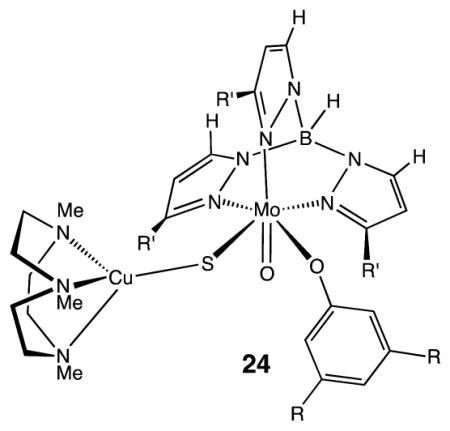
Structural models of [MoCu] CODHs are available, for example, the formally MoVCuI complex 24 (R = t-Bu, R′ = i-Pr).55 The EPR spectrum of this formally MoVCuI species indicates that the singly occupied molecular orbital contains significant Cu character, accounting for the large Cu hyperfine coupling constants observed. Functional models of [MoCu] CODH containing both Mo and Cu have proven challenging. Copper(I) readily forms 2-coordinate Cu(SR)2 sites, but synthetic compounds with molybdenyl-centers linked to such coordinatively unsaturated 2-coordinated copper centers remain elusive.55,56
4.3. Formate Dehydrogenases and Related Synthetic Catalysts
4.3.1. Metal-Independent Formate Dehydrogenases
The most prevalent class of formate dehydrogenases are NAD+-dependent. They play an important role in the energy conversion reactions of methylotrophic aerobic bacteria, fungi, and plants.57 These enzymes are thought to function by a direct hydride transfer from the C atom of formate to the C4 atom of the pyridine ring of NAD+, with hydride ion transfer being the rate-limiting step in the mechanism.58 Formate (and the competing substrate azide) and NAD+ are positioned in close proximity to facilitate hydride transfer. In the 1.1 Å structure, NAD+ is observed to adopt its bipolar conformation, which increases partial positive charge and electrophilicity of the C4 atom of the coenzyme and, thus, facilitates the hydride ion transfer.57a In vivo this reaction proceeds irreversibly.
This class of enzymes is characterized by the fact that both the proton and two electrons, in the form of a hydride, are transferred together from one site directly to another site. Azide (N3−), which is virtually isostructural with CO2, is a transition state analogue of both metal free and molybdenum formate dehydrogenases.58b In contrast, the Mo- and W-containing formate dehydrogenase enzymes oxidize formate by the transfer of two electrons to the Mo/W centers, concomitant with proton transfer to a cysteine or selenocysteine residue or a histidine residue of the protein.59 These Mo and W FDH enzymes will be discussed in more detail below.
4.3.2. Metal Complexes That Catalyze CO2 Reduction to Formate via Hydride Transfer
The direct reaction of metal hydrides and carbon dioxide has been studied to form either formate complexes or free formate.60 Quantitative studies of the factors controlling the hydride donor abilities of transition metal hydrides have been reported,15a and such studies will be important for further understanding of formate production catalysts of this type. Other studies have suggested formyl (MC(O)H) complexes as hydride donors in the reduction of CO2 to formate,61 and some formyl complexes are sufficiently good hydride donors to transfer a hydride to CO2.60d,62 Whether the hydride ligand is transferred from a metal center or a C atom of a formyl complex, these transition metal complexes share the common mechanistic feature of hydride transfer with the NAD-dependent FDH enzymes.
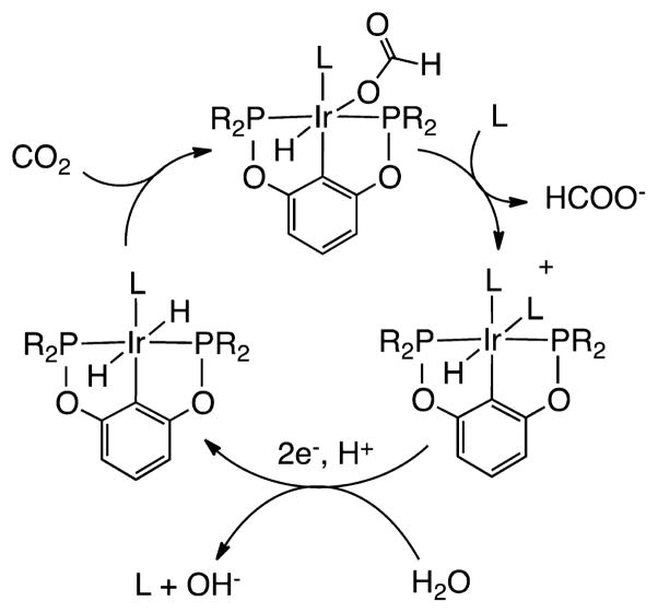
An Ir complex of an anionic PCP pincer ligand, Ir(PCP)-H2(MeCN), is a highly active electrocatalyst (kcat = 20(2) s−1 at 25 °C) that is selective for the reduction of CO2 to formate, producing only small amounts of H2 and CO (Scheme 4). It is also noted that solvent (water–acetonitrile) participates, by displacing the formate ligand, regenerating the electroactive species.63
Scheme 4. Proposed Mechanism for Electrocatalytic Reduction of CO2 to HCOO− by Ir(PCP)H2 (R = t-Bu, L = MeCN)63.
4.3.3. Catalysts with Redox-Active Ligands in CO2 Reduction
A number of molecular electrocatalysts for CO2 reduction contain redox-active 2,2′-bipyridine (bipy) ligands. These ligands provide sites for electron transfer separate from the metal binding site for the CO2. An example of a proposed catalytic cycle for formate production is shown by reactions 12–16 (Scheme 5) for cis-[Ru(bipy)2(CO)H]+.64 In reaction 12, one-electron reduction occurs at a bipyridine ligand enhancing the electron density on the hydride ligand and promoting insertion of CO2 into the M–H bond (reaction 13).
Scheme 5. Proposed Mechanism for the Reduction of CO2 to CO by cis-[Ru(bipy)2(CO)H]+.

A second one-electron reduction of the resulting formate complex (reaction 14) leads to loss of the formate ion (reaction 15). Protonation of the resulting neutral complex by water (reaction 16) completes the cycle. A key feature of this catalytic cycle is the redox “noninnocence” of bipy. The hydride complex of the radical anionic ligand complex, although coordinatively saturated, displays sufficiently enhanced nucleophilicity to attack CO2 to give the formate complex. The formate is labilized in the complex with two radical anionic ligands resulting in the cleavage of the Ru–O bond.
The related bis(bipy) complexes [Ru(bipy)2(CO)2]2+ or [Ru(bipy)2(CO)Cl]+ are also effective electrocatalysts for CO2 reduction. In a CO2-saturated H2O (pH 6.0)/DMF (9:1 v/v) solution at −1.5 V (vs SCE), the catalysts generate CO together with H2. Under more basic conditions (aqueous phase at pH 9.5), nearly equivalent amounts of formate and CO together with H2 are produced.46,65 These catalysts require only a single coordination site, as illustrated by the catalyst [Ru(bipy)(terpy)(solvent)]2+ (where terpy is 2,2′:6′,2″-terpyridine).66
It has also been shown that the formation of Ru(bipy)(CO)2 polymers on electrode surface can result in catalytically active electrodes for CO formation.67 Analogous third row transition metal complexes such as [Os(bipy)2(CO)(H)]+ catalyze the reduction of CO2 to CO in dry acetonitrile and a mixture of CO and formate in wet acetonitrile solution.68 Although the detailed mechanisms of these Ru and Os catalysts remain uncertain, it is clear from these studies that the nature of the environment, including the proton source and the solvent, plays an important role in controlling the product distribution.
The complexes ReI(bipy)(CO)3X (X = halides, phosphines, solvents and bipy = 2,2′-bipyridine and related ligands) represent another family of catalysts with redox-active ligands for electrochemical and photochemical CO2 reduction.69 For these catalysts, one- and two-electron pathways have been proposed for CO2 reduction where the first reduction is ligand centered and the second reduction is metal-based.40d,69b While the one-electron pathway is slow, the two-electron pathway via a doubly reduced species is fast; however, the two-electron pathway requires a large overpotential.
4.3.4. The Mo- and W-Formate Dehydrogenases
A second class of formate dehydrogenases contains molybdenum or tungsten centers in their active sites. These highly oxygen-sensitive enzymes can catalyze both the oxidation of formate (with rates as high as 3400 s−1 at pH 7.5) and the reduction of CO2 (with rates as high as 280 s−1).59 The structures of several of these enzymes have been reported.70 The oxidized form of the active sites contains W(VI) or Mo(VI) ions in a distorted trigonal prismatic geometry with four S atoms contributed by two pyranopterin ligands, a sulfur atom from a cysteine residue or a selenium atom from a selenocysteine residue, and either a sulfur or an oxygen atom in the sixth coordination site (structure 25 of Scheme 6).70 There are also two conserved arginine and histidine residues close to the metal center that likely participate in the catalytic reaction. The structure of the active site in the reduced form of the enzyme features a square pyramidal Mo or W center coordinated to four sulfur atoms from two pyranopterin ligands in the basal plane and a fifth ligand that is thought to be a sulfur atom in an apical position; see structure 26 of Scheme 6. The selenocysteine ligand that was coordinated to the Mo(VI) center in the oxidized form is no longer coordinated, and it is found to be 12 Å away from the Mo center.70
Scheme 6. Proposed Mechanism for Reduction of CO2 to HCOO− by Selenium- and Molybdenum-Dependent Formate Dehydrogenases.
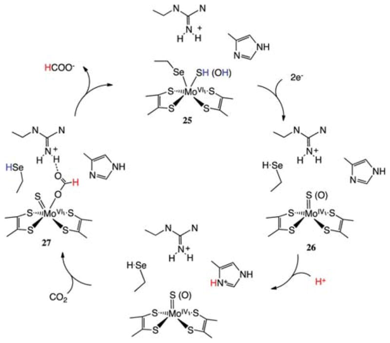
Binding of nitrite, a known inhibitor, to the oxidized form of the molybdenum enzyme results in a structure with one oxygen atom of the nitrite ligand bound to Mo, while the other is hydrogen bonded to an arginine residue, suggesting that these functional groups play similar roles in the binding of formate (structure 27 of Scheme 6). Modeling of formate in this active site places the proton of the formate ligand in close contact with a histidine residue. It is thought that the arginine residue assists in orienting the formate ligand for proton removal/delivery by the histidine residue.71 The role of the histidine residue in proton transfer to and from formate is supported by EPR data.72
An alternative mechanistic pathway involves the transfer of the proton to the selenocysteine residue followed by transfer to histidine. Kinetic isotope effects for the oxidation of HCOO− and DCOO− have been interpreted in terms of a primary isotope effect resulting from cleavage of the C–H bond.73 These structural, spectroscopic, and kinetic studies suggest the proposed mechanism shown in Scheme 6 with the rate-determining step being the formation/cleavage of the C–H bond. This C–H bond formation/cleavage step involves a coupled two-electron/one-proton transfer reaction. In contrast to the hydride transfer mechanism of the NAD-dependent FDH enzymes, the Mo- and W-containing enzymes transfer the two electrons and the proton to different sites. The two electrons from the C–H bond are transferred to (or from) the Mo or W centers, and the proton is transferred to (or from) a N of the imidazole ring (or possibly selenium). These electron-and proton-transfer processes are almost certainly coupled in the thermodynamic sense, and they may be concerted.
4.3.5. Metal Complexes That Catalyze the Reduction of CO2 to Formate via Coupled Proton and Electron Transfers
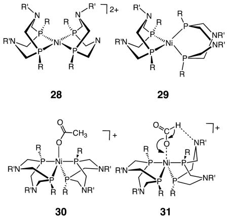
Insights into the formation and oxidation of formate have come from studies on complexes of the type [Ni(PR2NR′2)2]z. The oxidized state, [Ni(PR2NR′2)2]2+ (28), adopts a coordinatively unsaturated square planar (or weakly solvated trigonal bipyramidal) structure. Reduction by two electrons converts these square planar complexes to tetrahedral species (29). Complex 28 catalyzes the oxidation of formate to CO2.74 The acetate-bound oxidized state represents a kinetically stabilized model of the formate adduct. Crystallographic analysis of this acetate adduct indicates that formate binds through a single oxygen to form a trigonal bipyramidal species (30). These catalysts exhibit Michaelis–Menten kinetics, saturating at high formate concentrations. The turnover frequencies increase (from less than 1 to 16 s−1) as the pKa values of the conjugate acid of the pendant bases increase, and the kinetic isotope effects (HCO2−/DCO2−) are normal, between 3 and 7. Collectively, these observations suggest that the rate-limiting step for these complexes is similar to the Mo and W FDH enzymes. This slow step involves a proton transfer from formate to the N atom of the pendant amine and a coupled transfer of two electrons to the Ni center, as shown by the proposed transition state structure 31. Although 31 involves a Ni center as opposed to Mo or W centers for the FDH enzymes shown in Scheme 6, it appears that the mechanisms of C–H bond cleavage for the synthetic systems and the enzymes are similar, again illustrating the importance of bifunctional activation of the substrate.
4.3.6. Homogeneous Catalysts for CO2 Hydrogenation
Hydrogenation of CO2 is another pathway for reducing CO2 to formate using synthetic catalysts, but it does not appear to be a pathway utilized in biology. Although H2 gas at 1.0 atm pressure is a sufficiently strong reductant to convert CO2 to formic acid, high hydrogen pressures and/or bases are used to drive the formation of formate. A number of catalysts have been studied for CO2 hydrogenation, and some of these are listed in Table 1 together with the conditions and additives used.75 A large range of activities is observed. As shown in Table 1, the most active catalysts to date involve precious metals such as Ru or Ir. However, there are also catalysts based on first row metals such as Fe and Ni that may provide a fruitful avenue for future research. For hydrogenation catalysts, the turnover frequencies (TOFs) are generally given in terms of turnovers per hour instead of turnovers per second. The fastest catalysts are on the order of 100 000 h−1, which corresponds to TOFs of approximately 25 s−1. These rates require high temperatures and/or high pressures, which present challenges in terms of in situ spectroscopic characterization of the actual catalytic species. In addition to the bases and additives shown in column 3, the solvents play an important role in catalysis, and they vary widely from benzene, to polar organic solvents, to water and supercritical CO2.
Table 1.
Catalyst Precursors and Conditions for CO2 Hydrogenation to Formatea
| catalyst precursor | solvent | additives | H2/CO2 (atm) | T (°C) | TON | TOF (h−1) | ref |
|---|---|---|---|---|---|---|---|
| (PNPyP)IrH3 | H2O | KOH, THF | 25/25 | 200 | 300 000 | 150 000 | 75n |
| RuCl(OAc)(PMe3)4 | scCO2 | NEt3, C6F5OH | 70/120 | 50 | 31 667 | 95 000 | 75o |
| (PNPyP)IrH3 | H2O | KOH, THF | 29/29 | 120 | 3 500 000 | 73 000 | 75n |
| [Cp*Ir(phen)Cl]Cl | H2O | KOH | 29/29 | 120 | 222 000 | 33 000 | 75m |
| [Cp*Ir(OH2)(6HBPY)]2+ | H2O | KHCO3 | 5/5 | 120 | 12 500 | 25 200 | 75q |
| [Cp*Ir(OH2)]2(THBPM)4+ | H2O | KHCO3 | 20/20 | 50 | 153 000 | 15 700 | 75p |
| (PNHP)IrH2(O2CH) | H2O | KOH | 27/27 | 185 | 348 800 | 14 500 | 75l |
| [{(tppms)2RuCl2}2] + 2 tppms | H2O | NaHCO3 | 60/35 | 80 | 9600 | 75k | |
| (C6Me6)Ru(bis-NHC)Cl | H2O | KOH | 20/20 | 200 | 2500 | 2500 | 75d |
| RuH2(PMe3)4 | scCO2 | NEt3, H2O | 85/120 | 50 | 7200 | 1400 | 75g |
| Fe(BF4)2·6H2O + (PP3) | MeOH | NaHCO3 | 59/0 | 100 | 3850 | 770 | 75c |
| [RuCl2(C6H6)]2 + 4 dppm | H2O | NaHCO3, THF | 79/0 | 70 | 1374 | 687 | 75j |
| Ru(PEt3)4(H)2 | diols | N(hex)3 | 81/33 | 50 | 659 | 659 | 75i |
| Ru2(CO)5(dppm)2 | acetone | NEt3 | 35/35 | rt | 207 | 207 | 75h |
| RhCl(PPh3)3 | MeOH | PPh3, NEt3 | 20/40 | 25 | 2500 | 125 | 75f |
| [Cp*Ir(OH2)]2(THBPM)4+ | H2O | NaHCO3 | 0.5/0.5 | 25 | 7200 | 64 | 75p |
| [Rh(cod)Cl]2 + dppb | DMSO | NEt3 | 20/20 | 25 | 1150 | 52 | 75e |
| NiCl2(dcpe) | DMSO | DBU | 40/160 | 50 | 4400 | 20 | 75b |
| CpRu(CO)(μ-dppm)Mo(CO)2Cp | C6H6 | NEt3 | 30/30 | 120 | 43 | 1 | 75a |
Abbreviations: DBU = 1,8-diazabicyclo[5.4.0]undec-7-ene, dppm = CH2(PPh2)2, PP3 = tripodal tetraphosphine, dppb = Ph2P(CH2)4PPh2, dcpe = 1,2-C2H4[P(C6H11)2]2, cod = 1,5-cyclooctadiene, NHC = N-heterocyclic carbene ligand, tppms = P(C6H4-3-SO3Na)3, phen = 9,10-phenanthroline, PNHP = (i-Pr2PC2H4)2NH, PNPyP = C5H3N-2,6-[CH2P(i-Pr)2]2, THBPM = 4,4′,6,6′-tetrahydroxy-2,2′-bipyrimidine, 6HBPY = 6,6′-dihydroxy-2,2′-bipyridine, L = 4-(1-H-pyrazol-1-yl-κN2)benzoic acid-κC3).
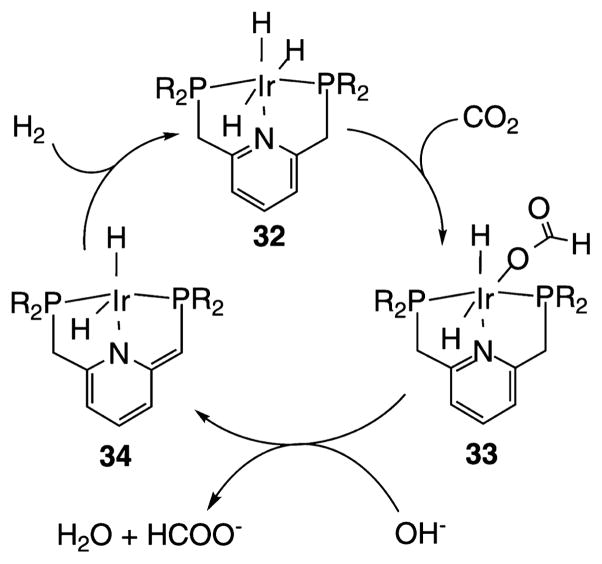
One of the most active catalysts for CO2 hydrogenation is the Ir(PNPyP)H3 pincer complex 32 shown in Scheme 7. This complex has a reported TOF of 150 000 h−1 (40 s−1, 200 °C, 25 atm H2, 25 atm CO2).75n On the basis of the isolation of presumed intermediates and their reactions with CO2, it is proposed that CO2 reacts with the trihydride species (32), transferring a hydride ligand from Ir to the C atom of CO2 followed by (or in concert with) ligation of the formate anion (33). Deprotonation and loss of formate is thought to result in the formation of a coordinatively unsaturated species (34) that reacts with H2 to regenerate the starting species. Similar reactivity is observed in related complexes where an NH group replaces the pyridine group. In such catalysts, important interactions are apparent between the NH center and the formate ligand, highlighting the influence of the second coordination sphere.75l However, the rates for this complex do not appear to be significantly faster than those of the analogous pyridyl complex or the previously reported H2Ru-(PMe3)4 of H(OAc)Ru(PMe3)4 complexes75o when corrections for temperature differences are taken into account. The close relationship between the Ir(PCP)H2 catalysts shown in Scheme 4 and the Ir(PNP)H3 catalysts shown in Scheme 7 reflects the potential synergy between the development of catalysts for CO2 hydrogenation and electocatalysts for CO2 reduction to formate.
Scheme 7. Proposed Mechanism for Hydrogenation of CO2 to HCOO− by Ir(PNP)H3 (R = i-Pr, t-Bu)75n.
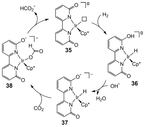
Another example of a very active catalyst is the iridium complex 35 with a proton responsive ligand shown in Scheme 8 that contains pendant bases (phenolate, ArO−) in the second coordination sphere. These catalysts exhibit high catalytic hydrogenation rates at ambient temperature and pressures.75p,q The rate-determining step is the heterolytic cleavage of H2 to form 36, which is assisted by the presence of the pendant base with the involvement of a water molecule.75s It has also been suggested on the basis of DFT calculations that a weak hydrogen bond may assist in the insertion of CO2 into the Ir–H bond, as shown in the conversion of intermediates 37 to 38. The loss of formate to regenerate 35 completes the catalytic cycle. Complexes strictly analogous to 35, but lacking the pendant base, are much less active catalysts. This observation as well as DFT calculations point to the important roles for the functional groups in the second coordination sphere. The bifunctional activation of H2 and CO2 proposed in this catalytic process is again similar to the multifunctional activation of CO2 observed in Mo- and W-formate dehydrogenases as well as NAD+-dependent formate dehydrogenases. A Moselenocysteine formate dehydrogenase in E. coli was shown to exhibit the ability to oxidize H2.76
Scheme 8. Proposed Catalytic Cycle for Formate Production by Ir Complex with Pendant Base in Second Coordination Sphere (Cp* = C5Me5−)a.
aThe box represents a vacant coordination site.75p,q
4.4. Heterogeneous Electrochemical Conversion of CO2 to CO and Formate
4.4.1. Background and Challenges
Significant attention has focused on heterogeneous electrochemical processes for the reduction of CO2 to products such as CO, formic acid, methanol, or even more reduced products. In these processes, the catalyst is immobilized on an electrode in an electrolysis cell. The catalysts used in these studies are often metals, or metal alloys, for example, in the form of nanoparticles. In a pioneering survey, Hori and co-workers surveyed and then classified metals according to their production of CO, formate, and hydrogen.77 For example, Sn catalysts yield almost exclusively formic acid, whereas the use of Ag favors the formation of CO. In contrast, Cu catalyzes the formation of C–C bonds, albeit with limited product selectivity (see Section 5.4).78 Thus, depending on the catalyst and operating conditions, either CO or formate may be produced in electrolysis cells in parallel with competitive formation of hydrogen gas. If water is oxidized to oxygen at the anode, the minimum or equilibrium cell potential for formation of CO is 1.33 V. Because of the large overpotential associated with CO2 reduction, cell potentials typically exceed 2.0 V when either CO or formate is produced at the cathode and O2 at the anode.
Steady advances have been made with respect to improving electrocatalyzed reduction of CO2.79 In this context, energetic efficiency is defined as the product of the Faradaic efficiency and the equilibrium potential divided by the applied potential, (iFaradaic/itotal)(E°/Ecell) (Figure 4). High Faradaic efficiencies (some >70%) and reasonable current densities (up to 600 mA/cm2) have been reported, but high current densities have not been demonstrated in the same experiment. Carbon monoxide and formic acid can be produced at reasonably high energetic efficiencies, but only at low current densities. Presently to obtain syngas (a mixture of CO and H2) for the Fischer–Tropsch process, hydrogen is best obtained by other routes. Research on CO2 electrolyzers remains focused on optimizing CO production.79
Figure 4.
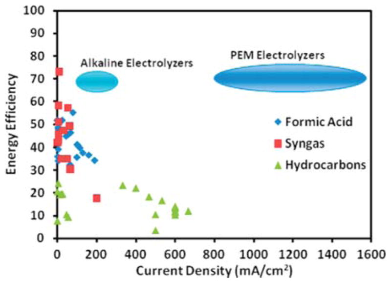
Comparison of the energy efficiencies and current densities for CO2 reduction to formic acid, syngas (CO + H2), and hydrocarbons (methane and ethylene) reported in the literature with those of water electrolyzers. Efficiencies of electrolyzers are total system efficiencies, while the CO2 conversion efficiencies only include cathode losses and neglect anode and system losses.79
The ideal catalyst will be immobilized on an electrode in a continuous flow electrolysis cell. Indeed, an electrolysis cell for the reduction of CO2 and H2O to CO and H2 was reported with a design similar to that of proton-exchange-membrane fuel cells (PEMFC), that is, based on the use of gas-diffusion electrodes.80 Introducing a pH-buffer layer (aqueous KHCO3) between the silver-based cathode catalyst layer and the Nafion membrane was necessary to achieve current densities of 80 mA/cm2. The CO/H2 ratio can be tuned by controlling the cell potential, but the maximum Faradaic efficiency for CO production was limited to about 80% at a current density of less than 20 mA/cm2. The performance of this system was probably transport-limited due to the high catalyst loadings on both the anode (Pt/Ir alloy) and the cathode (Ag).
While the performance of CO2 electrolyzers has improved, the major obstacle is still the high overpotential associated CO2 reduction. Elevated temperatures can help to significantly reduce the overpotential.81 Another study reported the use of an ionic liquid (1-ethyl-3-methylimidazolium tetrafluoroborate, EMIM-BF4) in aqueous media as a cocatalyst to reduce the typical overpotential of more than 0.8 V (cell potential >2.1 V) to less than 0.2 V (cell potential 1.5 V, just slightly above the equilibrium potential of 1.33 V) at the onset of CO formation.19 The Faradaic efficiency was remarkably high (>95%) independent of the cell potential. This significant reduction in overpotential was attributed to the stabilization of the CO2 anion intermediate by EMIM cation, thereby stabilizing this high energy intermediate at the interface of the Ag cathode catalyst (Figure 5).
Figure 5.
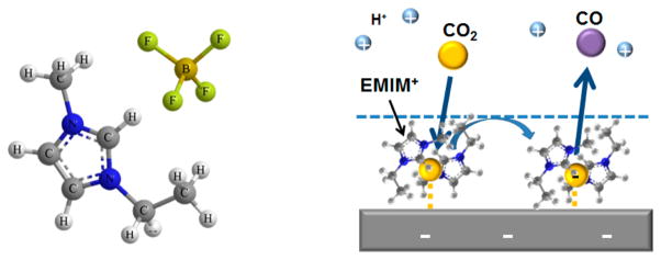
Left: Structure of EMIM+BF4− ion pair. Right: Schematic of the proposed cocatalytic mechanism in the reduction of CO2 to CO via a complex between the EMIM+ and the CO2·− radical on the surface of the cathode.19
This approach improved the energetic efficiency to close to 90%.19 Initially, current densities observed were low, less than 10 mA/cm2, but have been raised to >80 mA/cm2.81 To explain the preferential reduction of CO2 over protons, these authors invoke the intermediacy of a weak EMIM–CO2 complex.82 Thus, bifunctional activation of CO2 involving the Ag electrode and EMIM+ cation may play a role in the heterogeneous reduction of CO2 at low overpotentials, similar to the bifunctional activation observed in CODH enzymes.
4.4.2. Practical Considerations
To be commercially attractive, CO2 electroreduction requires energetic efficiencies of ≥60–70% and current densities ≥150 mA/cm2. Advances can be anticipated with improvements in deposition of catalysts during electrode preparation. For example, air-brushing leads to more uniform, thinner, and lower catalyst loadings. In contrast, most studies rely on on hand painting. Thinner catalyst layers minimize mass transport limitations as reactants and products now have to diffuse significantly less through a poorly defined structure.
The electroreduction of CO2 to formic acid has also been demonstrated using a microfluidic flow cell. Operating at acidic pH resulted in a significant increase in performance: Faradaic and energetic efficiencies of 89% and 45%, respectively, and current density of about 100 mA/cm2.83
5. REDUCTION OF CO2 BEYOND CO AND FORMATE
The focus of this section is the reduction of CO2 to the oxidation state of methanol and beyond in biological and chemical systems. In biological systems, metabolic pathways accomplish these multielectron reactions via a sequence of two-electron reduced products at the formate, formaldehyde, methanol, and methane (or acetate) oxidation states. For synthetic systems, the primary aim is to convert CO2 to reduced carbon compounds in a single reactor. Biological systems are tightly constrained energetically, whereas for synthetic systems there has traditionally been less emphasis on energy efficiency. Despite these differences, there are common lessons to learn, such as how to overcome thermodynamically unfavorable steps in the reduction of CO2 to the oxidation level of methanol or methane.
In biological systems, formate is activated and reduced to the level of formaldehyde, methanol, or even methane. In contrast, an enzyme that catalyzes the reduction of CO has not yet been found. Instead, in nature, CO is used in the generation of C–C bonds as discussed in the next section. However, the nitrogenase enzyme can be modified to reduce CO directly.84 In contrast to biological systems, for chemical synthesis it is the reduction of CO that constitutes the major pathway. The reduction of CO with hydrogen in the presence of suitable catalysts can lead to production of either hydrocarbons or methanol on large scales, but the reduction of formate to produce chemical products is not used commercially.
In the following subsection, the mechanism of the commercially viable heterogeneous hydrogenation of CO2/CO to methanol over supported Cu catalysts is described. This subsection is followed by a discussion on the pathways for reduction of CO2, in which the C1 chemistry proceeds through formate. This discussion is followed by a survey of research on the hydrogenation of methylformate to produce methanol using synthetic catalysts and the electrochemical reduction of CO2 to produce methanol and higher alcohols. Next, we summarize the discovery that nitrogenases can catalyze the reduction of CO to alkanes, alkenes, and even methane, which represents an enzymatic route for direct CO reduction. These two subsections serve as a useful starting point for discussions of current research. This is followed by discussions on current processes and challenges for converting carbon monoxide to more reduced products. The last section describes principles that can be used to improve the efficiency of homogeneous catalysts for the hydrogenation of aldehydes and ketones, leading to useful fuels.
5.1. Heterogeneous Hydrogenation of CO2
Hydrogenation of CO, CO2, or mixtures thereof has been of commercial interest for many decades and remains of high interest.85 Well known is the complete hydrogenation to methane and higher hydrocarbons, the Sabatier reaction and Fischer–Tropsch process, respectively. Particularly instructive within the context of this Review is selective hydrogenation of CO–CO2 mixtures to methanol. This conversion is practiced industrially86 with annual worldwide production being estimated at ~50 M metric tons (2006).87 The most common commercial catalyst is copper supported on a high surface area alumina, often promoted with zinc oxide. While the role for the promoter oxide is still the subject of considerable debate,88 the reaction can occur entirely on the surface of Cu metal86,89 present as submicrometer-sized particles distributed over the surface of the support. Numerous studies have been aimed at identifying the elementary steps and rate-limiting process-(es).86,88a,89a,90
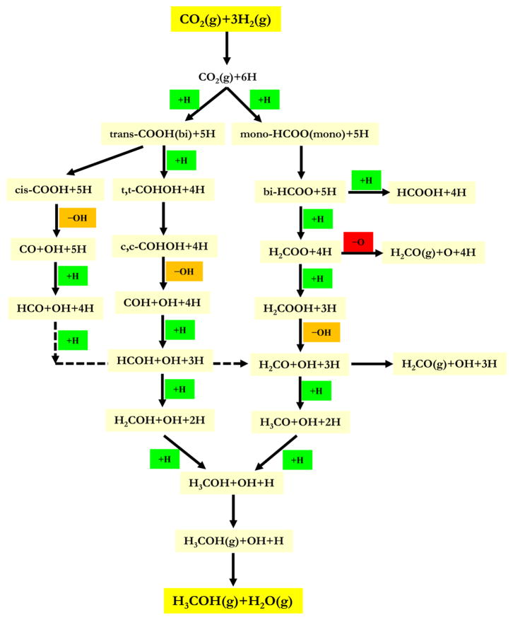
In the following, we first discuss the long-standing proposed reaction mechanisms for methanol synthesis.90 The “formate mechanism” involves an adsorbed formate intermediate, which ultimately leads to formation of methanol and water through several subsequent C- and O-hydrogenation, and C–O cleavage steps. Also widely discussed is the “CO-hydrogenation mechanism” involving first the formation of chemisorbed CO via the reverse water–gas shift reaction (RWGS; CO2 + H2 → CO + H2O), followed by several hydrogenation steps. The formate mechanism has long been preferred because (1) adsorbed formate on copper catalysts is readily observed spectroscopically with FT-IR under realistic conditions91 and (2) isotopic tracer studies have shown that, when both CO and CO2 are present under typical industrial conditions, CO2 is the primary source for methanol production.92 Emerging experimental evidence supports a “hydrocarboxyl mechanism” involving a chemisorbed hydrocarboxyl (COOH) that is inconsistent with either of the two previously proposed mechanisms.
5.1.1. Formate Mechanism
As depicted in the right-hand branch of Scheme 9,90a the formate mechanism is initiated by adsorption of weakly bound CO2 and dissociative adsorption of H2 to form chemisorbed H-atoms on the Cu surface (Note that the thermodynamics of the various reactions shown in Scheme 9 are contained in reference 90a). Addition of one H-atom to CO2 yields adsorbed formate. This species is readily observed by in situ FTIR spectroscopy.91 In fact, formate is apparently so stable that it can be formed during the water–gas shift reaction (WGS; CO + H2O → CO2 + H2), although for this process it is thought to be a spectator rather than an intermediate.93
Scheme 9. Three Proposed Pathways for the Copper-Catalyzed Hydrogenation of CO2 to Methanol94a.
aReproduced with permission from ref 94. Copyright 2013 Elsevier. The prefixes cis or c, trans or t, refer to the conformation of the partially hydrogenated substrate, and mono- and bi- refer to the number of copper centers attached to the substrate, one and two, respectively.90a
Chemisorbed formate on Cu surfaces can also be produced by adsorption of formic acid, and the reverse of this reaction is also possible leading to production of formic acid from CO2 and H2. However, formic acid is not observed as a product under typical methanol synthesis conditions.86 Instead, to continue to methanol via the formate mechanism, another H-atom adds to the carbon atom of the formate intermediate to form adsorbed dioxomethylene, –O2CH2. With a high estimated activation barrier,90 this step has been regarded as rate-limiting,88b which is also consistent with the presence of significant amounts of formate under steady-state reaction conditions. Dioxomethylene can, in principle, lose an oxygen atom to form formaldehyde as a product. This process is apparently not relevant to methanol synthesis because formaldehyde is not observed. Furthermore, this step has been calculated to have a quite high activation barrier.90a The nonobservation of formaldehyde during methanol synthesis is, in fact, one argument against the formate mechanism because adsorbed formaldehyde is also a proposed intermediate. In any case, methanol is proposed ultimately to form via another hydrogenation step that leads to adsorbed methoxy species, followed by hydrogenolysis of a Cu–OCH3 species.
5.1.2. CO Hydrogenation Mechanism
As depicted in the left branch of Scheme 9, the CO hydrogenation mechanism begins with the formation of an adsorbed hydrocarboxyl (–COOH) intermediate that arises via hydrogenation of one of the oxygen atoms in weakly adsorbed CO2. Thus, the difference between the initial step in the formate and CO hydrogenation mechanisms is H-atom addition to either the carbon atom (formate) or the oxygen atom (CO hydrogenation) of CO2. In the latter case, the hydrocarboxyl species is an intermediate for the reverse water–gas shift (RWGS) reaction to form CO and H2O, a process completed by loss of hydroxyl from –COOH to form CO and –OH, and subsequent hydrogenation of adsorbed hydroxyl to form H2O. Instead of completing the RWGS reaction, adsorbed CO and hydroxyl are also proposed intermediates for the formation of methanol and water as part of the CO hydrogenation mechanism for the methanol synthesis reaction.
As again depicted in the left branch of Scheme 9,90 the adsorbed CO is first hydrogenated to formyl (–HCO). This intermediate can then add another two H-atoms to form adsorbed methoxy, and finally methanol by hydrogenolysis of a copper methoxide. Alternatively, as proposed by Mei and coworkers,90a an H-atom first adds to the oxygen atom of the –HCO intermediate to form an adsorbed –HCOH species. This intermediate subsequently can add two more H-atoms to the carbon to form methanol.
In considering the likelihood of the CO hydrogenation mechanism, note that more recent calculations suggest that the essential first step is energetically unfavorable; that is, addition of H-atom to adsorbed CO to produce adsorbed formyl –HCO– is endothermic.90c Furthermore, as noted above, methanol is produced predominantly from CO2 even when both CO and CO2 are present,92 a result that is not readily reconciled by the CO hydrogenation mechanism.
5.1.3. Hydrocarboxyl Mechanism
Mei and co-workers proposed that methanol synthesis proceeds via a hydrocarboxyl mechanism based,90a in part, on the establishment of hydrocarboxyl, –COOH, as an intermediate in the water–gas shift reaction.90b,c,93 An important consideration is that adsorbed formate does not undergo hydrogenation under typical methanol synthesis conditions.89b In particular, removing CO2 from the reaction mixture (CO2 + H2) results in the immediate loss of methanol as a reaction product even though large concentrations of adsorbed formate remain on the copper surface. This observation is consistent with the high barrier calculated for this essential elementary reaction (–H + –HCOO → – H2COO) in the formate mechanism.90 However, in a similar experiment involving steady-state methanol synthesis in a CO2 + H2 gas mixture followed by removal of CO2, it was observed that addition of water (i.e., now an H2 + H2O mixture and a copper surface predominantly covered with adsorbed formate) yields substantial quantities of methanol.94 Initially, it was thought that water promotes hydrogenation of adsorbed formate. However, the calculated barrier for the elementary reaction, –H + –HCOO → –H2COO, increases in the presence of adsorbed water or hydroxyl species. In contrast, the formation of the hydrocarboxyl (–COOH) intermediate from CO2 and H-atoms is significantly promoted by the presence of water. Of course, this intermediate can decompose to adsorbed CO and hydroxyl as part of the RWGS mechanism, but then methanol needs to form from CO as in the CO hydrogenation mechanism. Instead, hydrocarboxyl itself has been proposed to undergo a number of hydrogenation and C–O scission steps to produce methanol as shown in the middle branch of Scheme 9.90a This mechanism proceeds via an initial H-atom addition to the second oxygen atom of adsorbed hydrocarboxyl followed by an isomerization of the resultant dihydroxylcarbene (–C(OH)2) species. Scission of one of the hydroxyl groups in dihydroxylcarbene yields adsorbed –COH. Addition of an H-atom to the carbon atom of this intermediate yields hydroxymethylene, –HCOH, that is also a proposed intermediate in the CO hydrogenation mechanism. As in this latter mechanism, two more subsequent additions of chemisorbed H-atoms to the hydroxymethylene intermediate yield methanol.
The hydrocarboxyl mechanism proceeds with lower reaction barriers than either the formate or the CO hydrogenation mechanisms. In addition, some of these barriers are in fact lowered by water, a product of methanol synthesis, in contrast to the rate-limiting hydrogenation of adsorbed –HCOO in the formate mechanism whose barrier is actually higher in the presence of coadsorbed water or hydroxyl.90a Furthermore, the hydrocarboxyl mechanism can account for the preference of CO2 as a reactant for methanol synthesis when both CO and CO2 are present.
5.2. Biological Reduction of Formate
Nature has evolved two phylogenetically unrelated pathways for the reduction of CO2 with H2 to the oxidation state of methanol: the acetogenic pathway with tetrahydrofolate (H4F, 40) as the C1-unit carrier and the methanogenic pathway with tetrahydromethanopterin (H4MPT, 39) as the C1-unit carrier.
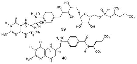
The C1 carriers H4F and H4MPT are analogous pterin-derivatives differing mainly in the pKa values of N(10), which arise from the different para-substituents of the arene ring attached to N(10). This results in different redox potentials of the N5,N10-methenyl-/N5,N10-methylene- and of the N5,N10-methylene-/N5-methyl couples.95 The acetogenic pathway (blue numbers in Scheme 10) involves free formate, N10-formyl-H4F (41a), N5,N10-methenyl-H4F (42), and N5,N10 -methylene-H4F (43) as intermediates yielding N5-methyl-H4F (44), its methyl group finally ending up in the methyl group of acetate. The endergonic formation of N10-formyl-H4F (41a) from formate is ATP driven. The reduction of the N5,N10-methenyl group to the N5,N10-methylene group and further to a N5-methyl group proceeds via hydride transfer from NAD(P)H catalyzed by transition metal free dehydrogenases. Electron transport from H2 involves [FeFe] and [NiFe] hydrogenases as enzymes, ferredoxin (E°′ = −500 mV) as one-electron carriers, and NAD(P) (−320 mV) as hydride carriers.
Scheme 10. Thermodynamic Relationships (298 K) between Reduced C1 Tetrahydropterin Derivativesa.
aEnergetics for the methanogenic pathway are shown in green and for the acetogenic pathway in blue. Water and protons are not shown.
The methanogenic pathway (green numbers in Scheme 10) involves a formamide derivative (N-formylmethanofuran) (the CO2/N-formyl-couple has the same redox potential, −520 mV, as the CO2/CO couple), N5-formyl-tetrahydromethanopterin (formyl-H4MPT, 41b), N5,N10-methenyl-H4MPT (42), and N5,N10-methylene-H4MPT (43) as intermediates yielding N5-methyl-H4MPT (44), its methyl group finally being reduced to methane. Electron transport from H2 involves the enzymes [NiFe] and [Fe] hydrogenases and ferredoxin (−500 mV) as one-electron carriers and the 5′-deazaflavin coenzyme F420 (−360 mV) as the hydride carrier.
Endergonic and exergonic reduction reactions with H2 in the two pathways are coupled such that the thermodynamic efficiency of CO2 reduction with H2 to the oxidation level of methanol is very high: essentially all of the reactions operate near thermodynamic equilibrium and are therefore reversible. Redox coupling proceeds via the recently discovered mechanism of flavin-based electron bifurcation.96 In this process, two electrons at the potential of H2 (−414 mV) undergo disproportionation in an enzymatically coupled process to reduce ferredoxin (−500 mV) and NAD+ (−320 mV) in the acetogenic pathway97 or ferredoxin and CoM–S–S–CoB (−150 mV) in the methanogenic pathway.98
Whereas the enzymes involved in CO2 reduction to the oxidation level of formate are molybdenum–iron–sulfur proteins or tungsten–iron–sulfur proteins (or their selenocysteine-containing isoenzymes), those catalyzing the conversion from the oxidation level of formate to the oxidation level of methanol do not contain transition metals, neither in the acetogenic nor in the methanogenic pathway. One design principle for catalysts for reducing formate to the level of methanol or methane is the activation or protection of formate. In nature, the hydroxy group of formic acid is replaced with an amide so that carbon center is susceptible to attack by hydride reducing agents. Thus, in acetogens, before formate is enzymatically reduced, it is converted to N5,N10-methenyl-H4F in two consecutive reactions catalyzed by a synthetase or formyltransferase to form N10-formyl-H4F (41a) and a cyclohydrolase to form N5,N10-methenyl-H4F (42), as shown in Scheme 10. In methanogens, the respective intermediates are N5-formyl-H4MPT (41b) and N5N10-methenyl-H4MPT (42). These findings indicate that formate has to be activated or protected before it can be reduced. A similar approach has proven useful for synthetic systems, as discussed in the next section. A second critically important principle is the coupling of endergonic and exergonic reactions (electron bifurcation) to drive important uphill steps required for substrate reduction.
5.3. Hydrogenation of Methylformate Using Synthetic Catalysts
The strategy of activating formate before reduction can be seen in the development of heterogeneous and homogeneous catalysts for the reduction of methylformate. Methylformate can be generated from either CO or formic acid by reaction with methanol.28 The methylformate generated in this manner can be hydrogenated using heterogeneous Cu catalysts, and this route is of interest due to the lower operating temperatures for this process as compared to the more commonly used route for the hydrogenation of CO/CO2 discussed elsewhere in this Review.99 Molecular Ru pincer complexes, such as those shown in Scheme 11, catalyze the hydrogenation of methylformate to methanol.100 These pincer complexes share structural similarities with the Ir pincer complexes (shown in Schemes 4 and 7) described above for the reduction of CO2 to formate. These complexes operate at temperatures between 80 and 145 °C and require H2 pressures of 10–50 atm.
Scheme 11. Proposed Mechanism for Hydrogenation of HCO2Me Using Ru Pincer Complexes100.
A key step in the catalytic mechanism is proposed to involve the transfer of a hydride ligand of 45 to the carbonyl C of methylformate in concert with a transfer of a proton from the methylene carbon of the tridentate ligand to the carbonyl O, as shown in transition state 46, to generate 47 and CH3OCH2OH. The latter eliminates methanol to give formaldehyde. Addition of H2 to 47 regenerates the trans dihydride complexes 45, which can then reduce formaldehyde to methanol. Similar pathways for the reduction of C=O bonds by Noyori catalysts are discussed in more detail below. Extension of these studies to inexpensive and abundant first row transition metals would be of much interest.
5.4. Electrochemical Reduction of CO2 Beyond CO and Formate
The electrochemical reduction of CO2 to produce multi-electron/multiproton products, such as methanol, is a long sought goal where only limited success can be claimed.18,101 Although a wide variety of metal77a and semiconductor18,101b electrodes have been surveyed, only copper electrodes and III–V semiconductors stand out as the materials that produce highly reduced products, that is, those beyond formate and CO.18,77,101a The original catalysts required large over-potentials, exhibited poor system stability, and often operated with very low Faradaic efficiencies (i.e., low product selectivity and yields). Overpotentials can be reduced by as much as 0.5 V by changing surface roughness.102 Labeling experiments with 13CO2, which have been usefully applied to related reactions,103 have not been described for these systems. Re-examination of the Cu-catalyzed reduction of CO2 to hydrocarbons has revealed even more diverse products, including C-3 hydrocarbons.104 Ongoing work suggests that the combinations of metal- and metal–oxide-based catalysts may provide strategies for tuning the selectivity for reduction of protons versus CO2.105
Pyridine and related heterocycles catalyze the selective transformation of CO2 to methanol77c,101b,106,107 and under certain conditions to higher order alcohols.101b,108 This finding is unexpected because the process involves one-electron/one-proton reduction pathways, not the multielectron processes that have been anticipated as necessary. Nonetheless, pyridinium, the prototypical catalyst in this class, is found to convert CO2 to methanol with ~300 mV of overpotential at a platinum electrode with ~25–30% Faradaic efficiency.106,107 When this homogeneous catalyst is employed in an aqueous CO2 saturated electrolyte at pH ≈ 5.2, in the presence of 10 mM pyridine and an illuminated p-type gallium phosphide (p-GaP) cathode is employed, a Faradaic yield of 96% is found for the formation of methanol.
It has been proposed that, independent of the electrode employed, the initial process is the reduction of a protonated pyridinium to form a one-electron reduced pyridyl radical,107c and that this species reacts with CO2 via a proton-de that is reduced in a similar manner to efficiently form methanol. These latter reductions are strongly dependent on the type of electrode surface employed. Computational studies indicate that reduction of the pyridinium salt is not mechanistically viable, but that reduction of CO2 is intimately associated with the platinum electrode (scheme 12).109,110
Scheme 12.

Regardless of the precise mechanism, specific aromatic aminium electrocatalysts in combination with specific electrode materials produce different distributions of electrode products including the formation of carbon–carbon bonded products.108,111 For example, p-type gallium arsenide (p-GaAs) photocathodes modified with platinum nanoparticles are found to be highly active for the reduction of CO2 to multicarbon products. Isopropanol, which involves the 18 electron reduction of CO2, is formed with ~60% Faradaic yield.111a The strong dependence of the product distribution on the electrode surface employed and subtle differences in the electrode surface strongly implicates multisite interactions as critical to an understanding of these processes.
5.5. Enzymatic Route for Direct CO Reduction
An enzyme whose primary function is the reduction of CO has not yet been identified. However, nitrogenase catalyzes the multielectron and multiproton reduction of dinitrogen (N2) to two ammonia (NH3) molecules, constituting the major mechanism for input of fixed nitrogen into the global nitrogen cycle.112 This difficult reduction, with an optimal stoichiometry of N2 + 8H+ + 16ATP + 8e− = 2NH3 + H2 + 16ADP + 16 Pi, utilizes three different Fe–S clusters to deliver electrons or to bind and reduce the N2. In the Mo-dependent enzyme, binding of N2 occurs at a cluster called the FeMo-cofactor with the composition [7Fe-8S-1Mo-1C-homocitrate] (Figure 6).113 Two alternative nitrogenases appear to utilize a similar cofactor, except that the Mo is replaced by V (V-nitrogenase) or Fe (Fenitrogenase).114 In addition to the reduction of N2 and protons, nitrogenase has been shown to reduce a number of non-physiological small-, double-, or triple-bond containing molecules such as acetylene (C2H2) to ethylene (C2H4).112a,115
Figure 6.
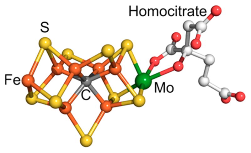
Structure of FeMo-cofactor in nitrogenase.
Although CO is a potent inhibitor of the Mo-based nitrogenase,116 the related vanadium-based nitrogenase slowly reduces CO to form a range of short-chain hydrocarbons including ethylene, ethane, propane, and propylene as shown in reaction 12.117 The formation of hydrocarbons by nitrogenase is reminiscent of the industrial Fischer–Tropsch process for the hydrogenation of CO over solid catalysts to form alkenes and alkanes. CO is known to bind to Fe atom(s) on one face of FeMo-cofactor,118 and such species are plausibly relevant to the CO hydrogenation by the V enzyme. Mutation of the amino acids near FeMo-cofactor affords nitrogenases that convert CO to a suite of hydrocarbons (reaction 17) at rates comparable to those seen in the V-nitrogenase.84 Many challenges remain in defining the factors that are important for the multielectron reduction of N2 and CO catalyzed by nitrogenase. It will be important to elucidate the possible roles of iron-hydrides119 as well as the influence of the protein cavity. One step in this direction is the observation that the isolated V–Fe and Mo–Fe cofactors also hydrogenate CO and cyanide.120
| (17) |
5.6. Chemical Pathways for the Reduction of CO
If carbon dioxide could be efficiently reduced to carbon monoxide, and if dihydrogen were readily available from a renewable or other nonfossil fuel derived source, many attractive products could be envisioned using current technologies and their extensions. Currently, syngas (H2 + CO) is readily obtained from natural gas, coal, and biomass, although the steam reforming processes used are very energy intensive and CO2 producing. Conversions to methanol using Cu/ZnO catalysts or to hydrocarbons by the Fischer–Tropsch process are relatively mature technologies. Syngas conversion to methanol is very efficient.87 On the other hand, Fischer–Tropsch processes with heterogeneous iron, cobalt, or ruthenium catalysts produce Schultz–Flory distributions of hydrocarbons, along with oxygenates, and these products require additional processing.121 Optimizing for any particular desired range of products, such as diesel, is strictly limited. Substituting homogeneous catalysts for heterogeneous catalysts appears to be an attractive possibility. In general, homogeneously catalyzed reactions are more selective than their heterogeneous counterparts; also, homogeneous catalysts can often be readily adjusted (by changing metals or ligands, for example) to tailor the product distribution, taking advantage of the detailed mechanistic understanding that can often be obtained, whereas for heterogeneous catalysts rational modification is more difficult. Research into homogeneously catalyzed syngas conversion first spiked in response to the oil crisis of the 1970s.122 Economic factors as well the significant technical hurdles that were quickly recognized led to declining interest in applying organometallic chemistry and homogeneous catalysis to these challenges. There is currently a major revival of interest driven by the recognition of new opportunities, particularly those suggested by the reduction of carbon oxides by biochemical catalysts.
The “obvious” first step of a homogeneously catalyzed CO hydrogenation would be migratory insertion of CO into a metal–hydride bond; however, it is now well established that this elementary step is substantially endoenergetic.123 The extreme conditions required for previously reported examples of homogeneous CO hydrogenation are most likely a consequence of this barrier, at least in part. External attack of a nucleophilic hydride (e.g., borohydrides such as [R3BH]−) on coordinated CO constitutes a much more facile method for formation of the first C–H bond.124 Incorporation of this step into a viable catalytic process has been problematic because it is difficult to regenerate the borohydride reagent. C–C bond formation also presents some difficulties, although methods exist for overcoming those in the context of CO chemistry, particularly with the aid of Lewis acid cocatalysts.125 There are promising examples of CO hydrogenation with transition metal reagents bearing pendant Lewis acids to reduced products having C–C bonds, but these are only stoichiometric at present.126 For these complexes, the formation of Lewis acid bonds to O can accelerate C–H and C–C bond-forming steps; however, balancing this M–O bond formation step with M–O bond cleavage reactions that are required to close catalytic cycles is a major current challenge.127
5.7. Reductions of Aldehydes and Ketones by Molecular Catalysts
An important intermediate in the reduction of CO or formate to methanol or methane is formaldehyde, and this leads naturally to an interest in catalysts that are capable of reducing aldehydes or ketones. The large-scale reduction of carbonyl-containing compounds has been practiced for over a hundred years. Early advances provided Raney nickel catalysts for aldehyde reductions and, in the Meerwein–Pondorf–Verly reductions, aluminum complexes and catalysts for aldehyde and ketones. However, these systems have low catalytic activities (turnover frequencies of 1–100 mol of product per mole of metal per hour), and the heterogeneous nickel systems have low selectivities. The advent of borohydride reagents provided a convenient and selective method, but it is stoichiometric, not catalytic. The need for high selectivity, particularly enantioselectivity in ketone reduction to provide pharmaceutical intermediates, has driven the development of homogeneous catalysts. The initial catalysts were very active platinum–metal-based systems, and more recent catalysts have used base metals such as iron and copper. Ketones are more challenging substrates than aldehydes due to their lower free energies of hydrogenation.
A Nobel-prize winning breakthrough in the hydrogenation of polar bonds was Noyori’s development of amine-hydride catalysts128 produced by activation of RuCl2(diamine)-(diphosphine) with base and H2.128 These catalysts are highly active with turnover frequencies (TOFs) greater than 400 000 mol of alcohol per mole of ruthenium per hour with the production of more than 2 000 000 mol of alcohol per mole of ruthenium under relatively mild conditions (45 atm, 30 deg). Catalysis occurs via an “outer-sphere” mechanism involving a six-membered intermediate, 48. The Hδ−Ru–NHδ+ site binds to a complementarily polarized δ−OCδ+ center of the ketone substrate (eq 18). Similar principles apply to aldehydes, imines,129 and even esters and amides.130 The free energy barrier for this process is low (approximately 8 kcal/mol), and the process is selective for carbonyl over nonpolar substrates such as olefins. These systems feature charge-neutral metal hydrides, which are particularly nucleophilic. A variety of related catalysts have been prepared using suitable N, P, C, and H donor ligands, with the low electronegativity donors situated trans to the hydride. The most active systems have a bifunctional character where the metal and ligand cooperate to deliver the proton and hydride equivalents. The carbonyl group of the substrate is activated to nucleophilic attack of the hydride ligand by interaction of the carbonyl oxygen atom with a proton bond to a nitrogen or carbon atom, and the proton transfer is enhanced by the transfer of a hydride ligand. A related and very active iridium catalyst with a tridentate ligand, IrH2(phosphine-amide-imine), likely operates by an inner sphere mechanism.131
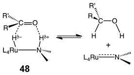 |
(18) |
Active iron-based catalysts for the reduction of ketones and aldehydes have been developed.132 These systems feature pincer imine-diphosphine ligands that, analogous to 49, are thought to operate using a bifunctional HFe–CH unit in the reduction of the polar bonds.132 Dihydrogen is activated by the basic carbon site on the ligand that is created after the alcohol product is released. A related family of catalysts are of the type trans-[Fe(L or X−)(CO)(phosphine-imine-imine-phosphine)]2+, which are activated with base.133 Turnover frequencies have been achieved of up to 55 000 h−1 at 28 °C for the transfer hydrogenation of acetophenone.134 A different catalytic motif utilizing iron is the iron complex, 49, shown below that is a derivative of cyclopentadienol.135
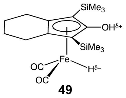
This complex features a hydride ligand and protic hydroxyl group poised to interact with polar substrates by the outer sphere, leading to transfer of H− and H+. More active are the related Ru derivatives including Shvo’s catalyst, Ru(H)-(C5Ph4OH)(CO)2.136 Finally, a copper hydride phosphine system represents another class of moderately active but cheaper metal catalysts.137
5.8. Comparison of Biological and Chemical Pathways for the Reduction of CO2 Beyond the Level of CO and Formate
Major differences exist between the biological and chemical routes to the reduction of CO2 beyond the level of CO and formate. Biological systems reduce formate under very mild conditions via the formation of C–H bonds to the level of methanol or even methane. Natural biological pathways involve a series of enzymatic steps to utilize CO to form C–C bonds, as well as C–H bonds (as discussed in section 6). Remarkably, a single enzyme, nitrogenase, can be modified to produce methane and other reduced carbon compounds (section 5.5). In addition, biological pathways are scalable from micro-organisms to entire ecosystems. In contrast, the predominant industrial pathway for the chemical reduction of CO2 beyond the level of CO or formate proceeds exclusively through CO. These chemical pathways currently require high temperatures and pressures. As a result, it may be difficult to scale these processes to applications suitable for widely distributed renewable energy sources.
Despite these apparent differences in the biological and chemical approaches to the formation of more reduced carbon products, there are common lessons. In biology, formate is activated prior to reduction. The same can be said for the homogeneous catalysts for the hydrogenation of methylformate.100 Formate reduction in the biological systems also involves the coupling of exergonic reactions with endergonic reactions to assist in driving thermodynamically difficult steps (electron bifurcation). Similar approaches will undoubtedly be useful in further development of chemical pathways for formate and CO reduction. Another central theme is the importance of the second coordination sphere in enhancing catalytic rates and controlling selectivity. For example, site-directed mutagenesis to change the nature of the amino acids adjacent to the active site of the nitrogenase enzyme plays a major role in the nature of the products observed. Similarly for ketone hydrogenation reactions carried out by transition metal complexes, the bifunctional delivery of a proton and a hydride to the polar C=O is important for fast and selective catalysis. Both the positioning of the different functional groups with respect to each other and the matching of their hydride and proton donor/acceptor abilities are critical to achieve the desired reaction. It is clear that much can be learned from comparing biological and chemical systems and that new routes may be developed on the basis of common themes such as multisite activation of substrates and energetic coupling of reactions.
6. C–C BOND-FORMING REACTIONS INVOLVING CO AND CO2
The formation of carbon–carbon bonds by reactions with CO is instrumental in many industrial processes138 and in the biological carbon cycle.139 Such C–C bond-forming reactions will be of even more importance if fuels are made from CO2, rather than from such reduced C1 molecules as methanol. Yet, some striking similarities exist between natural and synthetic systems. For example, the intermediate steps in the Monsanto process for industrial acetic acid formation from methanol and CO are comparable to those in the catalytic mechanism of the Ni-enzyme, acetyl-CoA synthase (ACS) (Scheme 13). The enzyme activates CO toward reaction with a methyl group (donated by the corrinoid iron–sulfur protein, CFeSP) and coenzyme A to generate acetyl-CoA, which serves as a source of energy and cell carbon for various anaerobic microbes.140 The stoichiometries of the carbonylation using CO (involving only ACS) or CO2 (requiring both CODH and ACS) are shown in eqs 19 and 20.
Scheme 13. Comparison of Biological and Chemical Pathways for C–C Bond Formationa.
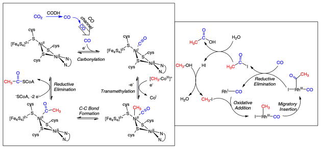
aLeft: Enzymatic mechanism of acetyl-CoA synthesis by the Ni-metalloenzyme ACS. In the CODH/ACS complex, CO2 is reduced by CODH to generate CO, which is channeled to the ACS active site, where it combines with a methyl group and CoA to generate acetyl-CoA. Right: Mechanism of acetic acid synthesis by the Monsanto process, showing only the key steps and fragments at the metal center. It consists of “organo” and a “metallo” cycles, the later having steps similar to those for ACS.
| (19) |
| (20) |
In the Monsanto process, the methyl donor is methyl iodide, which is generated in situ from methanol, the net reaction being shown in eq 21.
| (21) |
Both the biological and the homogeneous catalysts involved in C–C bond formation use organometallic mechanisms that feature low-valent metal centers (e.g., RhI vs NiI) to facilitate formation of metal–carbon bonds (e.g., CH3–M, M–CO) by oxidative addition reactions. Furthermore, the key carbon–carbon bond-forming reactions involve a migratory insertion (intramolecular nucleophilic attack) of the metal-bound CO and methyl groups to generate an acyl-metal intermediate. In the Monsanto process, this acyl-metal intermediate undergoes reductive elimination by coupling the acyl ligand with an adjacent iodide ligand to release the product acetyl iodide.141 By contrast, in the enzyme, the Ni-acyl couples to the thiolate of Coenzyme A, reductively eliminating the thioester acetyl-CoA. Aspects of this intermetallic C–C coupling process have been replicated in models, including the alkylation of low-valent Ni complexes by methyl cobalt compounds.142
Besides the Monsanto process, many other examples of homogeneous catalytic processes involve these fundamental reaction steps, including hydroformylation in which a hydride migrates to an alkene ligand to generate a metal–alkyl that in turn migrates to the CO ligand, forming the metal-acyl that reacts with hydrogen to form the aldehyde. Similarly, the Pd-based industrial Reppe processes developed by BASF, Toyo Rayon, and Shell lead to the carbonylation of alkenes, alkynes, and conjugated dienes.143 Perhaps lessons can be learned from the natural systems that would stimulate the development of a new generation of bioinspired catalysts with superior properties, as discussed below.
6.1. Comparisons of and Contrasts between the Biological and Synthetic Catalytic Systems
Despite considerable mechanistic similarities, obvious contrasts exist among the metal centers and the coordination environments of the catalysts used in the homogeneous and enzymatic systems. Metalloenzymes mainly feature transition metals from the first row, whereas synthetic homogeneous catalysts usually contain the heavier transition metals. In ACS, Ni is the active site, whereas second- and third-row transition metals (Rh, Ir, Pd, etc.) are most common in commercial carbonylations, for example, the Monsanto and hydroformylation reactions.141 Hydrocarboxylations are exceptions where nickel remains a popular metal for certain applications.144
The active site in ACS, shown schematically on the left side of Scheme 13 and more graphically on the left side of Figure 7, is called the A-cluster. The active site is a Ni center (called the proximal nickel because of its proximity to the Fe–S cluster) that is attached, via thiolate bridges, to a second Ni site (called the distal nickel) and to a Fe4S4 cluster. As in the homogeneous reaction, a single metal center, the proximal Ni, binds the CO, CH3, and acetyl groups. The distal Ni center may fine-tune the electronic properties of the active site, as has been replicated in models.145 The Fe4S4 cluster participates directly in internal redox reactions with the catalytic Ni site. In contrast, in synthetic carbonylation catalysts, the ligands are not connected to redox centers. Carbonylation affords the best-characterized state of ACS.146 This state features a NiI–CO center, which has been studied by a variety of spectroscopic (EPR, ENDOR, Mossbauer, X-ray absorption, IR)75k,147 and computational148 methods. It has been shown to be a kinetically competent intermediate in the mechanism.149 Model complexes have replicated key C–C bond-forming reactions of ACS.142
Figure 7.
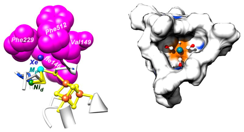
First and second coordination spheres of ACS and hydroformylation catalyst. Left: The A cluster and the cage of hydrophobic residues near the proximal Ni ion surrounding the gas molecule (a Xe atom in the crystal structure). Based on PDB 2A8Y.150 Right: A rhodium tricarbonyl tripyridylphosphine hydrido complex (HRh(CO)3(PAr3)) embedded in a supramolecular cage formed by a self-assembly of zinc(II) porphyrins around the tripyridylphosphine template.
One reason that the heavier (less abundant and more expensive) metals are used in the homogeneous chemical processes is that they promote two-electron type reactivity for facile oxidative addition (bond-breaking) and reductive elimination (bond-making) reactions. In addition, the second row d9 and d10 metals give stable 16-electron square planar complexes, which represent important intermediates for many catalytic cycles. Nature deals differently with controlling the reactivity of their first row transition metal catalysts. In general, complex metal clusters containing thiolate ligands fine-tune the oxidation state of the catalytic centers and act as electron-transfer conduits to deliver electrons as required. For example, the thiolate bridge between the proximal Ni and the Fe4S4 cluster at the ACS active site serves as an effective conduit for electron flow, allowing the unpaired electron in the NiI–CO state to delocalize among the proximal Ni, CO, and the Fe4S4 components of the A-cluster.147b,151 The amido dithiolato coordination environment of the distal Ni stabilizes the NiII state, whereas the sulfur-rich environment of the proximal Ni allows it to undergo reduction to the NiI state. The internal electron shuttle, proposed in the ACS mechanism,152 has precedence in the active site of the [FeFe] hydrogenases (Figure 1), which also features an Fe4S4 cluster attached to a substrate-binding center. Intriguing examples from synthetic chemistry are CoIII complexes ligated with two redox-active (“noninnocent”) amidophenolate ligands.153 The complex can undergo oxidative addition reactions, without changing the oxidation state of the cobalt. Electrons flow to the redox-active ligands and are stored temporarily. Subsequent reaction with zinc-alkyl reagents leads to C–C bond formation via a reductive elimination reaction in which electrons flow back from the ligands.
One of the other general differences between biological and synthetic catalysts is the nature of the ligands in the first coordination sphere. In metalloproteins associated with organometallic transformations,154 the metals are generally bound in sulfur-rich environments provided by sulfido and thiolate ligands. For synthetic catalysts, phosphorus-based ligands are more common, for example, in rhodium- and cobalt-based hydroformylation catalysts.141
The second coordination sphere, as defined by functional groups that can interact with substrates but not with the metal center, plays an important role in enzymatic catalysis. Substrates are precisely oriented to react in a specific manner with the active site. As shown on the left side of Figure 7, ACS contains a gas binding cage composed mainly of hydrophobic amino acids (isoleucine, valine, and two phenylalanine residues) located within 4 Å of the proximal Ni to which CO binds.150 The steric confinement provided by this cage enhances the selectivity for CO near that catalytic metal center. For synthetic systems, we are just beginning to incorporate second coordination sphere control of catalyst reactivity, and a few examples exist in which a functional group of a substrate interacts with functional groups of the catalyst adjacent to the substrate-binding site.155 Such interactions orient the substrate with respect to the metal, which can lead to exceptionally high selectivity. For reactions with substrates that do not have functional groups other than those involved in the chemical transformation, one can design enzyme-type pockets or cages around the active site. The right side of Figure 7 displays RhH(CO)3(P(pyridyl)3) in the core of a cage formed by self-assembly of zinc porphyrins that bind via Zn–N bonds to the templating P(pyridyl)3 ligand. Uniquely, this rhodium complex selectively hydroformylates internal alkenes, because of the steric confinement provided by the cage.156
6.1.1. Beyond the Second Coordination Sphere, the Outer Coordination Sphere
A defining feature of the enzymatic synthesis of acetyl-CoA is the method by which CO is delivered to the A-Cluster active site of ACS. CODH, which was discussed in section 4.2, and ACS form a 300 kDa macromolecular complex that works as a machine in which CO2 is reduced to CO by CODH. CO then travels over 70 Å through a hydrophobic tunnel into the cage (above) at the active site of ACS.150 This tunnel allows for tandem catalysis, effecting tight coordination, and coupling of CO2 reduction to acetyl-CoA synthesis. It also prevents loss of CO, the generation of which requires a significant expenditure of energy (E°′ = −520 mV vs NHE). In synthetic systems, catalysts can be placed in cages, leading to systems that display interesting properties in terms of activity and selectivity. The next level of complexity would be the application of well-defined cages in which entrance of various reagents is controlled.157
6.2. Challenges and Goals for the Future
For the determination of catalytic mechanisms, the ideal is to trap each intermediate and obtain detailed structural information. For the mechanistic study of transition metal-catalyzed processes, several in situ spectroscopic techniques have been developed, although even with such sophisticated methods, observation of the key intermediates is unlikely to be straightforward, and only the resting or inactive states are observable. A mass spectrometric method has been developed for identification of less-stable but more active intermediates.158
Illustrative of the promise and problems are mechanistic studies on ACS. Computational results148 combined with biochemical and spectroscopic experiments147a–c,159 and studies of model complexes145b,c suggest that the proximal Ni is the binding site for the carbonyl group and that the Ni–CO is paramagnetic.146 Both the NiI species to which CO binds and the methyl-NiIII state, which rapidly undergoes reduction to methyl-NiII, are very unstable. In fact, the NiI was generated by photolysis of the NiI–CO and is only observable below 20 K.146 The NiI–CO intermediate is formed in an electron-transfer reaction that is kinetically coupled to CO binding, a strategy that is similar in principle to the well-studied proton-coupled electron transfer (PCET) that drives many related chemical reactions.160
The role of the various components in the ACS active site is not yet known, for example, the role of the distal Ni in ACS. As the distal Ni appears to remain in the NiII state during catalysis, it may fine-tune the properties of the proximal Ni and could perhaps serve a Lewis acid role, as has been proposed for the FeII in the CODH mechanism (above).31a In homogeneous catalysis, catalytic enhancement has been achieved by including one metal as a redox center and the other as a Lewis acid. The redox center is most reactive and can also serve as a nucleophile. The “Lewis acid” center also can help to enforce selectivity and provide electronic and steric control. This Lewis acid role is well studied in various CO2-activating enzymes that contain mononuclear non-redox metals as Lewis acids to bind substrates and stabilize anions, for example, M–OH in carbonic anhydrase and M–CO2 (oxy-bound) in carboxylation reactions involving biotin carboxylases, ribulose bisphosphate carboxylase oxygenase (RuBisCO), and phosphoenol pyruvate carboxylase.158
Another challenge in the enzymatic system is to understand the internal electron transfer pathway that is coupled to the carbonylation and methylation steps in the pathway (see Bender et al.152 for details). The coupling of the various stages of metal–carbon and carbon–carbon bond formation to rapid and efficient electron transfer appears to be a key feature of ACS catalytic reactivity. The inclusion of redox centers to harbor additional electrons and to stabilize reactive low-valent metal centers is a strategy that should be considered in the development of more active homogeneous catalysts.
Finally, it is important to understand how dynamics are coupled to the catalytic event, which is highly topical in enzyme catalysis.161 Large conformational movements in CODH/ACS38 and in the CFeSP facilitate the methyl transfer reaction preceding carbonylation162 and couple this reaction to acetyl-CoA synthesis. Dynamics are also recognized to play a key role in homogeneous catalysts, for example, in the syndiotactic migration of a methyl group to an olefin.163
6.3. Enzymatic Carboxylation: Biotin-Dependent Carboxylases
The biotin-dependent carboxylases have remained an unexplored resource for using CO2 as a feedstock for fuels. Moreover, the mechanism by which the biotin-dependent carboxylases utilize carbon dioxide as a substrate to form carbon–carbon bonds may provide insight into the development of chemical catalysts that carry out the same chemistry. Biotin-dependent carboxylases are multifunctional enzymes that catalyze their reactions via a two-step reaction mechanism shown by reactions 22 and 23, where biotin has the molecular structure shown by 50.
| (22) |
| (23) |
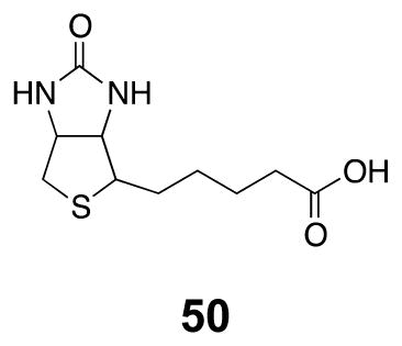
Reaction 22 involves the carboxylation of biotin and is identical for all of the biotin-dependent carboxylases. Reaction 23 involves the transfer of the carboxyl group from biotin to an acceptor molecule. The acceptor molecule denotes the name of the enzyme. For instance, if the acceptor is acetyl-CoA, then the enzyme is acetyl-CoA carboxylase.
6.3.1. Fixation of CO2
Bicarbonate serves as the source of CO2 for all biotin-dependent carboxylases and is activated by reacting with ATP to form a carboxyphosphate intermediate (eq 24).164
 |
(24) |
The mechanism by which the carboxyl group is transferred from carboxyphosphate to biotin is unknown. Two possible mechanisms are (1) the carboxyphosphate decomposes in the active site to form CO2 and phosphate and biotin reacts with CO2, and (2) biotin reacts directly with the carboxyl group on carboxyphosphate. The first mechanism is attractive because the carbon in CO2 is more electrophilic than a carbon in a carboxyl group. The first reaction in biotin-dependent carboxylases requires 2 equiv of metal ions. The metal ion used in nature is magnesium; however, cobalt and manganese will work equally well.165 One of the metal ions is bound to ATP such that the metal-nucleotide chelate is the substrate for biotin carboxylase, while the role of the other metal is unknown.
6.3.2. C–C Bond Formation
Once CO2 has been fixed onto biotin it is then transferred to an acceptor molecule by a carboxyltransferase, Scheme 14. The common theme for this reaction is that carbon–carbon formation proceeds via an enolate anion in the acceptor molecules as well as the biotin.
Scheme 14.
For those biotin-dependent carboxylases with an acyl-CoA acceptor molecule, the enolate anion is stabilized with an oxyanion hole, which is consistent with carboxyltransferase being a member of the crotonase superfamily of enzymes.166 The crotonase superfamily of enzymes are all characterized by having oxyanion holes that stabilize the formation of enolate anions in their substrates.167 The oxyanion holes used by biotin-dependent carboxylases to stabilize the enolate anion contrast with the mechanism used by the other major carboxylases. Ribulose bisphosphate carboxylase168 and phosphoenolpyruvate carboxylase169 both use Mg2+ to stabilize the enolate intermediate.
The mechanism by which the carboxyl group is transferred from biotin to the acceptor molecule is also unknown. It has been proposed that carboxybiotin undergoes a decarboxylation so that CO2 is the species that reacts with the enolate. The other major question concerning the carboxyltransferase step is what is the base that abstracts the proton from the acceptor to generate the enolate? It has been proposed to be biotin after it undergoes decarboxylation, an example of substrate-assisted catalysis. However, other enzymes in the crotonase superfamily of enzymes have been shown to use a glutamic acid residue as a base,167b and sequence alignments of acetyl-CoA carboxylase with other crotonase family enzymes do in fact reveal a homologous glutamic acid residue.
6.3.3. Biotin-Dependent Carboxylases and Fuel Production
While biotin-dependent carboxylases are excellent catalysts for using CO2 to form carbon–carbon bonds, it is the products of the reactions that might be useful for generating fuels. For instance, the product of the reaction catalyzed by acetyl-CoA carboxylase is malonyl-CoA. Removal of the CoA by hydrolysis or a thioesterase would generate malonic acid, which could be reduced to propanediol or completely reduced to propane. The biotin-dependent carboxylases propionyl-CoA carboxylase and pyruvate carboxylase could conceivably generate isobutane and butane, respectively.
Several possible advantages exist for using biotin-dependent carboxylases as catalysts for fuel production. First, all of the genes encoding the enzymes have been cloned and actively overexpressed; thus, ample amounts of enzyme are available. Second, the TOF of acetyl-CoA carboxylase is about 5 s−1 at pH 8. Because the Km value for bicarbonate is around 0.4 mM,170 and the concentration of bicarbonate at the catalytically optimal pH values of 7–8 ranges from 50 to 500 μM, respectively, the enzyme operates at subsaturating levels with respect to the substrate bicarbonate. As a result, the rate of catalysis by acetyl-CoA carboxylase in vitro and in vivo is not at maximal velocity. If acetyl-CoA carboxylase could be combined with carbonic anhydrase and the carboxysomes (discussed below) to increase the local concentration of bicarbonate, then the turnover number could potentially double. Third, as with most biological catalysts, high turnover is achieved at room temperature and atmospheric pressure (i.e., high temperatures and pressures are not required to catalyze CO2 fixation).
The major disadvantage to using biotin-dependent carboxylases as catalysts for fuel production is that they require a continuous input of ATP and the acceptor molecule. However, the reaction catalyzed by acetyl-CoA carboxylase could be coupled to ACS (above) to provide a continuous source of acetyl-CoA. Moreover, acetyl-CoA carboxylase functions equally well in aerobic and anaerobic environments so coupling to the oxygen-sensitive ACS poses no obvious problem.
In conclusion of this subsection, if the remaining questions concerning the CO2 fixation and carbon–carbon bond formation can be answered, biotin-dependent carboxylases have promise in the conversion of CO2 into feedstocks for fuel production, and may also provide useful insights into possible synthetic models.
6.4. RuBisCO-Catalyzed C–C Bond Formation
A large part of CO2 assimilation in the biosphere proceeds through the process of photosynthesis, which annually converts an estimated 263 × 109 tons of CO2 into biomass.2 A key step in this process is the catalytic addition of CO2 to ribulose 1,5-bisphosphate by the enzyme, RuBisCO (eq 25). RuBisCO is an extremely slow catalyst, with turnover frequencies of approximately 1 s−1. Thus, to accomplish sufficient levels of CO2 fixation, organisms produce large quantities of RuBisCO (up to 50% of leaf protein), making it one of the most abundant proteins on earth. Because of the key role played by RuBisCO in CO2 fixation, it has been a target for numerous genetic manipulations aimed at improving its specificity for CO2, decreasing its vulnerability to O2, and/or its carboxylation catalytic activity.171 Interestingly, RuBisCO enzymes that exhibit low specificity values have higher turnover rates, whereas those enzymes with high specificity values have lower turnover rates (eq 25).172
 |
(25) |
Crystal structures of complexes of the enzyme with substrate, product, or inhibitors have provided key insight into the catalytic reaction, shown in Scheme 15. Figure 8 shows the structure of the Chlamydomonas reinhardtii RuBisCO complexed with the reaction intermediate analogue, 2-carboxyar-abinitol-1,5-bisphosphate (2CABP).173 Catalysis requires an activation step involving the binding of CO2 and Mg2+ to complete the active site. The spontaneous activation step is nevertheless facilitated by another enzyme, RuBisCO activase, which removes a variety of otherwise inhibitory sugar phosphates from the active site.174 In the activation step, the free amino group of an active-site lysine residue reacts with CO2 to form a carbamate (KC201 in Figure 8), which is synergistically stabilized by monodentate coordination to a magnesium ion (green sphere in Figure 8).175 A lysyl carbamate also serves as the bridging ligand between two NiII ions in urease176 and two ZnII ions in phosphotriesterase.177 Catalytic activity also involves a conformational change, which closes the enzyme around its substrates, thus ordering and preventing solvent access to the active site.178 As described in the other sections, activation of other CO2 activating enzymes, for example, CODH, ACS, is required; however, for these enzymes, it is a redox activation of the active site metal center. In RuBisCO, the carboxy-lysine stabilizes the bound Mg2+ and forms a H-bond with the substrate.
Scheme 15. Proposed Mechanism for the Fixation of CO2 by RuBisCO.
Figure 8.
Structure of the active site of RuBisCO complexed with 2-carboxyarabinitol-1,5-bisphosphate. Based on PDB 1UZD.173
The catalytic reaction mechanism168 is initiated by binding and coordination of the substrate, ribulose 1,5-bisphosphate (RuBP). When RuBP binds, two waters are released from Mg2+ as the C-2 and C-3 hydroxide groups of the substrate coordinate to the metal ion. Bound RuBP then undergoes dehydration to generate the metal-stabilized enediol form of RuBP, which then reacts with CO2 and H2O to form a 6-carbon intermediate (2′-carboxy-3-keto-D-arabinitol 1,5-bisphosphate, 2C3KABP). The reaction of CO2 with an enolate intermediate is an interesting example of C–C formation that is also used by pyruvate carboxylase179 and phosphoenolpyruvate carboxylase.180 CO2 addition to RuBP by RuBisCO occurs without net reduction and relies on the nucleophilicity of the enolate.
The structure of RuBisCO complexed to an analogue (2′-carboxy-D-arabinitol 1,5-bisphosphate, CABP, Figure 8) reveals the many hydrogen bond and ionic interactions between the transition state intermediate and RuBisCO’s active-site residues and bound Mg ion.173 The oxygen atoms attached to C-2 and C-3 of 2CABP coordinate to MgII in the cis conformation, forming (with an oxygen from the newly attached carboxy group) two fused five-membered rings. The bound 2C3KABP intermediate then undergoes C–C bond cleavage to release two equivalents of 3-phosphoglycerate (Scheme 15), which is assimilated into cellular biomass by further reactions of the reductive pentose phosphate pathway, or Calvin–Benson–Bassham cycle.
Enolates are susceptible to oxidation, and thus in RuBisCO catalysis oxidation of the enediolate intermediate by atmospheric O2 is competitive with its carboxylation, leading to the formation of phosphoglycolate, instead of 3-phosphoglycerate. The phosphoglycolate must be recycled in a process called photorespiration, which can limit carbon fixation by up to 50%.171 More complicated CO2 fixation processes have evolved in so-called C4 and CAM plants to concentrate CO2 around RuBisCO and thus suppress photorespiration. These plants first capture atmospheric CO2 with phosphoenolpruvate carboxylase that combines more abundant bicarbonate (which is in about an 80:1 equilibrium with CO2 dissolved in cellular water) with phosphoenolpruvate to give the C4 acid oxaloacetate, which is further reduced to malate. These acids are subsequently decarboxylated in either spatially separate organelles (C4) or temporally (CAM) to effectively concentrate CO2 around RuBisCO in the chloroplasts for refixation. Plants using C4 or CAM can better exploit environments where C3 plants suffer from high rates of photorespiration. The trade-off is that CO2 fixation in these plants requires more energy.181
6.5. Two-Electron Reductions of CO2 Involving Formation of a C–C Bond Catalyzed by Molecular Electrocatalysts
In addition to the possibility for forming C–H bonds, two-electron reductions of CO2 by molecular electrocatalysts may also result in the formation of C–C bonds. Reaction of Grignard reagents with CO2 has been used for many years to prepare carboxylic acids. The uncatalyzed electrochemical carboxylation of organic halides (RX) results in the formation of esters, RCOOR. These esters are formed by the reduction of the alkyl halide to form a carbanion, followed by reaction with CO2 to form a carboxylate anion (RCO2−). Reaction of the carboxylate anion with unreacted organic halide in solution produces the ester. As a result, carboxylation of only 50% of the original halide is possible.182
For catalyzed reactions, the best understood system for C–CO2 bond formation is the electrocarboxylation of bromoarenes in the presence of a transition metal catalyst, reaction 26.183 This reaction, catalyzed by Ni(dppe)Cl2 (where dppe is 1,2-bis(diphenylphosphino)ethane) or Pd(PPh3)2Cl2,183a,b,d is selective and occurs at room temperature and 1 atm of CO2.
| (26) |
Mechanistic studies indicate that, depending on the metal, two different catalytic cycles are involved. In the case of the Ni complex, the first step is the reduction of Ni(dppe)Cl2 to a transient Ni(dppe) species.183b This process occurs in two one-electron steps (reaction 27). Bromobenzene then oxidatively adds to the resulting Ni(dppe) complex to form Ni(dppe)-(Br)(Ph), reaction 28. The NiII aryl species that is formed is then reduced in a one-electron process to form Ni(dppe)(Ph), which reacts rapidly with CO2 to form a Ni–CO2 intermediate as shown in reaction 29. The rate-determining step for the overall catalytic reaction is the insertion of CO2 into the Ni–aryl bond, reaction 30, step 1. This reaction is followed by a final one-electron reduction to regenerate “Ni(dppe)”, the catalyst in the cycle (reaction 30, step 2).
| (27) |
| (28) |
| (29) |
| (30) |
In a related carboxylation, the Pd(PPh3)2(Ph)Br, an analogue of Ni(dppe)(Ph)Br (see reaction 28), undergoes a single two-electron reduction followed by expulsion of the aryl group, which then reacts with CO2 to form PhCO2−.183a In this case, the role of the Pd complex is simply to lower the overpotential associated with the reduction of bromobenzene to form the phenyl anion.
The formation of C–C bonds between CO2 and alkenes and alkynes can also be catalyzed. For example, benzonitrile catalyzes the reductive coupling of CO2 and styrene to form mono- and dicarboxylic acid products.184 This transformation requires very negative potentials (−2.15 V vs SCE) and is fairly unselective. CO2 can also be incorporated into alkynes in a reaction catalyzed by nickel 2,2′-bipyridine complexes.185 This catalytic process requires a single compartment cell and the use of magnesium as the counter electrode. For this system, Mg2+ ions produced by oxidation of the Mg electrode are required to form the ultimate product. An extension of this chemistry is the reductive coupling of two molecules of CO2 to butadiene to form the conjugate base of 4-hexene-1,6-dioic acid (51), an unsaturated precursor to adipic acid,186 precursor to Nylon (reaction 31, S = solvent). The catalyst is the nickel complex of the tridentate ligand 2,4,4-trimethyl-1,5,9-triazacyclododecene. Although not commercially developed, these C–C bond-forming reactions indicate that in the future, electrochemical coupling of various organic substrates to CO2 could provide attractive routes to various carboxylic acids and their derivatives.187
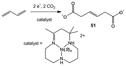 |
(31) |
Related metal-catalyzed processes, electrochemical and otherwise, have been identified for the coupling of CO2 and alkenes. In this way, routes have been identified for the preparation of acrylates and pyrones.188
7. NON-REDOX REACTIONS OF CO2 IN CARBON METABOLISM BY BIOLOGICAL SYSTEMS AND PARALLEL CHEMICAL SYSTEMS
The preceding sections have discussed various processes for the reduction of CO2 and the formation of C–C bonds. In this section, we are interested in how biological systems capture CO2 from the atmosphere and how CO2 may be concentrated within organisms. In parallel with these discussions, we will examine briefly how CO2 is currently captured by the chemical industry and possible new approaches that could lead to improved efficiencies. Two specific biological examples will be discussed: carbonic anhydrases and the cyanobacterial carbon-concentrating mechanism, which includes a bacterial organelle composed entirely of protein, the carboxysome.
7.1. Carbonic Anhydrases
Carbonic anhydrases (CAs) catalyze the reversible hydration of CO2 to form bicarbonate and a proton in aqueous solutions as shown in reaction 32. These enzymes are essential to many aspects of CO2 metabolism. Because the rate for the uncatalyzed interconversion between CO2 and HCO3− is generally slow as compared to the rates at which CO2 is fixed and produced by metabolic processes, carbonic anhydrases play an important role in CO2 metabolism in both plants and animals. For C3 plants, carbonic anhydrase may not contribute significantly to CO2 fixation. However, for C4 plants and cyanobacteria, it has been estimated that the rates of CO2 fixation are enhanced by approximately a factor of 104 by the presence of carbonic anhydrases.189 Carbonic anhydrases are very fast enzymes with typical turnover frequencies between 104 and 106 s−1.
| (32) |
On the basis of sequence and structural homology, CAs have been grouped into five structural classes that appear to have evolved independently with different amino acid sequences.190 These different carbonic anhydrases are associated with different types of organisms. The most frequently studied are the α-CAs found in mammals, while β-CAs are found in chloroplasts, and both β- and γ-CAs are found in cyanobacteria.191 With the increasing availability of genomic and metagenomic data, new variants of these and possibly entirely new classes remain to be discovered. In addition, growing evidence points to an unexpected plasticity in the nature of the catalytic metal; for example, the zeta CAs, found in marine diatoms, use either zinc or cadmium.192 Likewise, a subset of the gamma CAs (which are found in every domain of life) have been shown to bind iron.193 The binding is sensitive to oxygen; exposure to air results in the loss of the metal and, consequently, activity.
As shown in Scheme 16, the active sites of most CAs contain a Zn2+ ion coordinated to three histidine residues and to water or hydroxide. The coordination of water increases its acidity to a pKa value of approximately 7. This low pKa allows the coordinated water to be deprotonated with weak bases to produce a hydroxide ligand. This hydroxide can then undergo a nucleophilic attack at the carbon atom of CO2 to produce a bicarbonate stabilized by hydrogen bonding to a Thr residue and possibly other residues in the second coordination sphere.194 A hydrophobic pocket formed by Val residues assists in the positioning of the CO2 molecule for nucleophilic attack by the hydroxide ligand. Displacement of bicarbonate (or carbonic acid that is immediately deprotonated) by water regenerates the catalyst. Key features of this mechanism are the activation of water by binding to Zn2+, the precise positioning of CO2 in a hydrophobic pocket, and hydrogen bonding sites positioned in the second coordination sphere of Zn that activate water and stabilize the transition state for bicarbonate formation. Similar to the enzymes described above for CO2 reduction, the multifunctional activation of water and CO2 made possible by residues in the second coordination sphere is critical to the high activity of these enzymes.
Scheme 16. Proposed Catalytic Cycle for Carbonic Anhydrase.
In addition to basic characterization (including other functional attributes, like proton channels) of the diversity of naturally occurring CAs and their metals, key challenges for developing industrial-scale robust systems with biological CAs include engineering longevity, thermostability, and tolerance of harsh conditions such as components of flue gas. In addition, for more practical applications, it will be important to develop optimal geometries, matrices, and methods for immobilizing the enzyme and tuning the enzyme for optimal rates and directional catalysis.
Studies of the CO2 binding site in the alpha class carbonic anhydrase HCAII provide a model for other CO2 binding enzymes.195 Structural analyses of HCAII establish that CO2 binds in a hydrophobic pocket, resulting in no structural changes, explained in part by passive binding with interaction distances of about 4 Å to the hydrophobic residues. However, the crystal structures also suggest a role for the amide nitrogen of Thr199 interacting with one of the oxygen centers of CO2 at a distance of 3.5 Å. This weak interaction, coupled with the linear geometry of CO2, orients the oxygens of CO2 roughly equidistant from the zinc-bound water ligand (3.0 and 3.1 Å). These interactions result in a side-on orientation of CO2 with respect to the zinc–water, placing the CO2 carbon at a distance of 2.8 Å from the water ligand so as to optimize it for nucleophilic attack by the lone-pair of electrons on the zinc-bound hydroxide.
7.2. Synthetic Models of Carbonic Anhydrase
The relatively simple coordination environment of zinc in the carbonic anhydrase active site (three imidazole N atoms and water or hydroxide) suggests that the synthesis of functional and structural models of these enzymes might be straightforward. The challenges associated with the otherwise labile and sterically unprotected tetrahedral zinc center have been surmounted by using complexes of bulky tris(pyrazolyl)-hydridoborates, a family of monoanionic tridentate ligands. Bulky substituents are required to suppress the formation of hydroxide bridges. For example, the hydroxide complex 53 has been synthesized and characterized by X-ray diffraction methods and by various spectroscopic methods using the trispyrazolylborate ligand with 5-methyl and 3-t-butlyl substituents on the pyrazolate rings.196 The hydroxide complex 53 and related complexes have been shown to be functional models of carbonic anhydrase (eq 33).197 For 52, 17O NMR spectroscopy has demonstrated the catalytic exchange of oxygen atoms between CO2 and H217O, a reaction that is also catalyzed by carbonic anhydrase.196 In another strategy, a de novo-designed peptide containing a ZnII binding site for catalytic activity and a HgII site, which provides structural stability, was shown to catalyze CO2 hydration with an efficiency that is only ~500-fold less than that of carbonic anhydrase.198
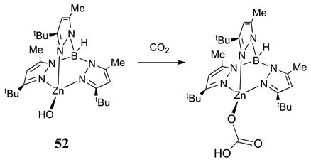 |
(33) |
7.3. Cyanobacterial Carbon-Concentrating Mechanism and Carboxysomes
Cyanobacteria are ecophysiologically diverse organisms that carry out oxygenic photosynthesis. They have evolved a carbon concentrating mechanism (CCM) that consists of active uptake of inorganic carbon across the cell membrane and a specialized subcellular compartment, the carboxysome, for the fixation of CO2 (Figure 9).199 The CCM is effectively an integrated system that operates at the cellular level; as such, not only the individual enzymes but the scale and organization of the whole system offer inspiration for biomimetic carbon capture and fixation systems.
Figure 9.
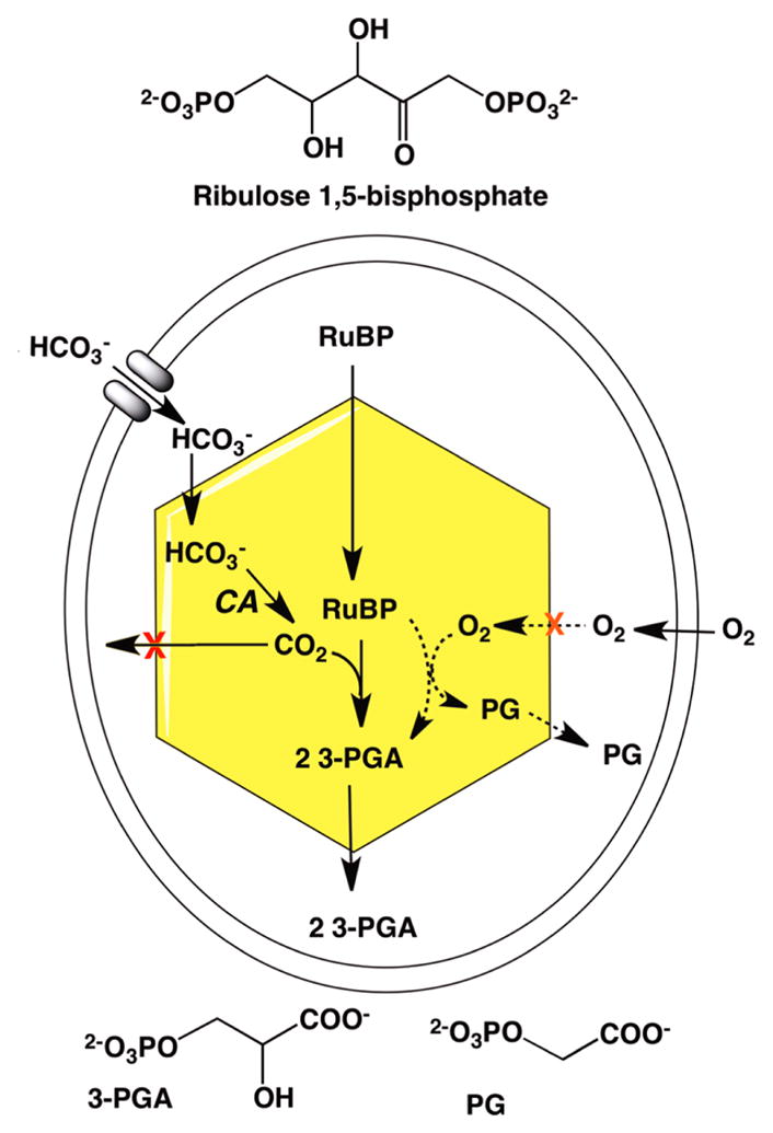
Schematic of a cyanobacterial cell illustrating the carbon concentrating mechanism. Shown in the cell is a single carboxysome. Relevant enzymes and metabolites that cross the cell membrane and carboxysome shell are shown. Reactions related to photorespiration catalyzed by RuBisCO in the presence of oxygen are shown in dashed lines. Adapted from Kinney et al.199b
The active uptake of inorganic carbon (Ci) from the environment raises the Ci level within the cell; the accumulated bicarbonate diffuses into the carboxysome. The carboxysome is composed of protein shell that encapsulates CA and RuBisCO. The CA converts the bicarbonate into CO2, the substrate for RuBisCO, which catalyzes the CO2 fixation to produce two molecules of 3-PGA. The 3-PGA diffuses out of the carboxysome into the cytosol where the downstream enzymes of the Calvin cycle can convert PGA into a hexose sugar. The oxygenase reaction generates one molecule of PGA and the two-carbon phosphoglycolate (PG), effectively short-circuiting the Calvin cycle.
Consideration of several features of the CCM illustrates principles that may prove useful in the design of synthetic carbon capture and fixation systems. For example, the carboxysome shell is presumed to be selectively semipermeable to favor the passage of bicarbonate over other molecules into the interior.199b,200 The rapid conversion of bicarbonate into CO2 by the encapsulated CA maintains the concentration gradient that drives the bicarbonate diffusion, and also generates an environment rich in CO2 near the active site of RuBisCO.191a It is also thought that the shell may help protect the enzyme from O2, a competitive inhibitor that is generated in the light reactions of photosynthesis. Given the polyhedral profile of the carboxysome and evidence from imaging methods, it is surmised that the enzymes in the interior of the carboxysome are organized201 to allow for substrate and product channeling. Some organization would seem to be necessary, considering that the diameter of the carboxysome is usually 100–150 nm, to facilitate catalysis and metabolite flow in the center of the organelle. On a cellular level, the spatial distribution of carboxysomes also appears to be regulated for function,202 not only for equitable distribution of the organelles at cell division, but also for optimal diffusive uptake of the cytosolic bicarbonate pool.
Key advances in deepening our understanding of the CCM will come from approaches focused both on the structures of individual proteins and protein complexes, advanced imaging methods (such as XFELs203) applied to intact carboxysomes, as well as cellular-level understanding of the dynamics of carboxysome organization.
7.4. CO2 Capture Using Chemical Sorbents
With few exceptions,204 the conversion of CO2 to fuels requires concentrating CO2 from dilute streams. For the resulting fuels to be carbon-neutral, the captured CO2 must originate from air or from sources that would otherwise emit the CO2 to the atmosphere, thereby resulting in no net increase in atmospheric CO2 concentration when the fuel is utilized.205 This recycling of atmospheric CO2 resembles biological cycles, even more so if it were powered by solar energy.
Many approaches are currently being pursued for the capture of CO2 from fossil fuel power plants to decrease the carbon footprint of fossil energy.206 The use of the CO2 captured from these power plants to generate carbon-based fuels from nonfossil energy sources does not contribute to CO2 sequestration for the power plant, but CO2 from power plants may function as a temporary source of CO2. Assuming that the use of fossil fuel will decline due to either a finite supply or policy changes, then the future source of CO2 for fuel production will be the atmosphere. The capture of CO2 from air could have more immediate benefits as well: for example, orphaned, carbon-neutral energy sources may not have a more concentrated CO2 source available for the production of carbon-neutral, carbon-based fuels. Additionally, if carbon capture and sequestration (CCS) is implemented for fossil fuel power plants, not all of the power plants have the onsite space for a CO2 capture unit, and some are not within suitable proximity of a sequestration site.
Numerous methods have been investigated for separation of CO2 from fossil fuel power plants, but these methods are not usually suitable for CO2 capture from air.207 Physical sorbents are unlikely to have binding capability or selectivity to be able to efficiently separate CO2 from air due to the low partial pressure of CO2 (0.0004 atm). Because of their low energy efficiencies for separations from dilute sources, pressure swing methods and passive membranes will not be discussed. Metal–organic frameworks (MOFs) are an active area of research for the development of new materials for CO2 capture. This approach exploits the relatively high quadrupolar moment of CO2, which, at 3× that of competing molecules such as N2, enhances the affinity of the gas for the polar bonds that comprise these extended solids (Figure 10).17,208 The porosity and reactivity of MOFs are exquisitely tunable, although barriers remain to their practical viability.
Figure 10.
Partial structure of the CO2 adduct of the MOF Ni2(dobdc). Green, gray, and red spheres represent Ni, C, and O atoms, respectively.208
Of the known chemical sorption methods, many do not bind CO2 strongly enough to capture CO2 from air, with the predominant exception being hydroxides. The capture of CO2 from air with hydroxides has been proposed, with regeneration methods such as electrodialysis209 or thermal regeneration from CaCO3.207,210 For electrodialysis, water splitting is required (E ≥ 1.23 V), but this large energy penalty for CO2 capture could be offset using multiple dialysis membrane pairs or through the use of the resulting H2 for CO2 hydrogenation. For thermal regeneration, estimates of the efficiency have been made210b,c but are quite low due to the energy required to liberate CO2 from carbonate salts, such as CaCO3. A promising approach to CO2 capture using hydroxide involves a dispersed anion exchange resin. In the hydroxide form, such resins can be saturated with CO2 and then regenerated to liberate the CO2 by hydration.211
An alternative approach to traditional thermal cycles or electrodialysis for the sorption and desorption of CO2 is through the use of an electrochemical cycle to change the oxidation state of a CO2 sorbent, thereby changing the affinity of the sorbent from a form that favors CO2 binding to a form that favors CO2 release. This approach has been studied for two general classes of electrochemically switchable CO2 sorbents: quinones and bimetallic complexes.212 Through a two-electron reduction in an aprotic solvent, quinones were converted to the corresponding dianionic catecholate species, which reacted with CO2 to form organic carbonates. These in turn were reoxidized by two electrons to regenerate the starting quinone and CO2. The potentials for the overall reaction were observed to be low and could be utilized for CO2 capture from air, with the exception that the reduced, CO2 binding forms of the quinones are sensitive to oxygen.212b,c
Bimetallic complexes have been reported as an alternative, wherein the CO2 capture form was the oxidized, and thereby oxygen-stable, form of the CO2 sorbent.212a In this case, CO2 bound to the metal complex as carbonate that was formed by dissolution of CO2 in water. These bimetallic complexes of copper were demonstrated to be effective for separating CO2; however, the binding constants observed were inadequate for separating CO2 from air. Further work in this area is needed to move to air-stable complexes capable of capturing atmospheric CO2.
The direct capture and reduction of CO2 may be advantageous; however, very few chemical systems are known to exhibit both activities. The most prominent example is the dicopper(I) complex reported by Bouwman204 that reacts with atmospheric CO2 to form a bridged complex containing four copper centers and two oxalates, indicating a one-electron reduction of each CO2 by oxidation of each copper(I) to copper(II). This approach was demonstrated to be catalytic in the presence of lithium salts to form lithium oxalate. The selectivity of the reaction and mild potential both indicate great promise, but an understanding of how to improve the catalytic rate will be essential, as the observed TOF was ~0.5 h−1.
7.5. Comparison of Biological and Chemical Systems for CO2 Capture
The majority of chemical approaches to CO2 capture utilize only the first coordination sphere, such as the direct binding of CO2 to hydroxide. However, biological approaches make effective use of additional interactions with the substrate through the second coordination sphere and beyond. Biological systems clearly demonstrate that the capture and reduction of CO2 from air can be accomplished without prohibitive energy expenditure, but chemical systems to date have been unable to replicate this approach. In biological systems, the binding energies for substrates are carefully balanced to be sufficient to allow catalytic transformations to proceed while not forming unreactive intermediates. Additionally, substrate binding is controlled through subtle changes in structure rather than in typical chemical approaches such as heating or mechanical pumping. A greater understanding of the precise control mechanisms in biological systems may benefit chemical approaches.
8. ELECTRODE MODIFICATION, PHOTOCHEMICAL SYSTEMS, AND TANDEM CATALYSIS
Discussions presented to this point have focused primarily on catalytic transformations of CO2 and its reduced derivatives. Implicit in any conversion of CO2 to fuels is the input of energy in the form of either electrons and protons or H2. This consideration should focus attention on modalities for coupling energy sources with catalytic systems. For example, the utilization of electrical energy generated by photovoltaic devices, wind, or nuclear energy to reduce CO2 could take place at an electrode surface. Alternatively, small particles or even molecules capable of converting light into electrical energy in the form of electron–hole pairs can provide the driving force required for CO2 reduction. These considerations raise interesting issues associated with the coupling of catalysts to energy sources such as electrodes or light harvesting particles and molecules. Thus, the generation of these interfaces is important.
Modification of electrodes with molecular electrocatalysts or enzymes for CO2 reduction has been reported. For example, Hirst and co-workers have shown that electrodes modified with formate dehydrogenase enzymes can catalyze both CO2 reduction to formate and the reverse reaction at high rates.59 Similarly, CODH enzymes have also been attached to electrode surfaces and shown to catalyze both the electrochemical reduction of CO2 and the oxidation of CO,213 and TiO2 nanoparticles modified with CODH and [Ru(bipy)3]2+ derivatives catalyze the photochemical reduction of CO2 to CO in the presence of sacrificial electron donors.214
For molecular electrocatalysts, one of the first examples of modified electrodes involved the reduction of CO2 to CO by [Ni(cyclam)]+ (13 in Chart 1) adsorbed on Hg.39b In this case, the adsorbed catalyst exhibits higher activity, selectivity, and turnover numbers than the homogeneous species. Subsequent studies showed that the N-methylated derivatives of [Ni-(cyclam)]2+ exhibit improved catalytic activity on a Hg electrode,215 although certain isomers of [Ni(cyclam)]2+ are effective in homogeneous solution using carbon electrodes.216 Similarly, carbon electrodes modified with cobalt phthalocyanines have been reported to produce CO,217 and polymeric thin films of [Ru(bipy)(CO)2]n on carbon and platinum catalyze the reduction of CO2 to CO in both organic solvents and water.218 Polymeric films derived from the electrochemical polymerization of vinylbipyridine and vinylterpyridine complexes of Re and Co, and polypyrrole/Schiff-base complexes of nickel, catalyze the electrochemical reduction of CO2 to CO and formate.219
Photochemical reduction of CO2 has been achieved using sacrificial electron donors and a variety of catalysts and sensitizers. These photocatalytic systems may involve catalysts and sensitizers that both diffuse independently in solution, covalently linked sensitizer-catalyst complexes (supramolecular catalysts), or, even more surprisingly, systems for which the light absorber and the catalyst are the same complex.69a Some of the challenges in this area of linking catalysts to energy sources lie in the development of attachment methods that (1) are simple and do not require synthetically difficult catalyst modifications, (2) do not degrade the catalyst performance in terms of rate and selectivity, and (3) provide facile access of substrates (electrons, protons, CO2, etc.) and departure of products from the catalytic active sites.
In addition to coupling the catalyst to the energy source (electrode or sensitizer), the coupling of individual catalytic reactions (tandem catalysis) can also be important. The control of substrates, intermediates, and products in biological systems is often the result of a series of linked catalytic reactions in which the product of one reaction is the substrate for the next reaction. For reactions near equilibrium, depleting the product of one reaction by using it as the substrate of the subsequent reaction can increase the driving force for the first reaction to proceed. This approach, along with the fine control provided by the sophisticated structures utilized in biological systems, appears to allow much lower substrate concentrations to be used than would be possible in the absence of such coupling.
An obvious example of coupled reactions is the photosynthetic reactions of the Calvin cycle, in which CO2 reacts with a 5-carbon sugar, ribulose bisphosphate, to form two molecules of phosphoglycerate. This reaction is catalyzed by the enzyme ribulose bisphosphate carboxylase (RuBisCO), as discussed in section 6.4, and involves both the formation and the cleavage of C–C bonds. The phosphoglyceric acid is phophorylated and then reduced in a second two-electron step involving NADPH. Overall, a four-electron reduction of CO2 to the level of a sugar (or formaldehyde) is achieved in photosynthesis. An example of a synthetic system based on enzymes is the reduction of CO2 to methanol using a combination of an electron mediator and two enzymes, formate dehydrogenase and methanol dehydrogenase. This system operates with current efficiencies as high as 90% and with low overpotentials.220 The high selectivity and efficiency of this system indicate the potential of enzyme cascades or tandem catalysis. Another example of this approach using synthetic catalysts is the hydrogenation of CO2 to methanol using three catalysts and a cascade sequence involving: (a) hydrogenation of CO2 to formic acid, (b) esterification to generate a formate ester, and (c) hydrogenation of the ester to form methanol.221 Challenges in the development of tandem catalysis include assuring that the reaction conditions, such as solvents, temperature, and pressure, required for one catalyst are compatible with those required by the catalysts for subsequent reactions and that reactants or products of individual catalytic reactions do not inhibit any other desired catalytic reactions in the cascade.
9. CROSS-CUTTING ACTIVITIES
To guide the development of improved catalysts for the transformation of CO2 to fuels, the structures of the enzymes and synthetic catalysts must be elucidated in various states, resting, inhibited, as well as under catalytic conditions. Required are the usual structural tools including XAS and X-ray diffraction techniques as well as more conventional spectroscopic techniques such as NMR, UV–vis, and infrared spectroscopy that can be implemented under high pressures or temperatures and/or at interfaces such as at an electrode surface. For probing Fe-containing proteins (e.g., CODH, ACS), nuclear resonance vibrational spectroscopy (NRVS) is an emerging synchrotron-based tool.222 A recurring challenge is the detection of hydride ligands, which have been proposed to exist as in the NiFe-based CODH.223 Hydride ligands are weak chromophores and invisible to protein crystallography. Synthetic analogues of proposed hydride-containing intermediates represent useful complements to biophysical studies.224
Of central importance is the synthesis of new catalysts to test hypotheses generated by mechanistic and structural studies of enzymes and their synthetic analogues. The synthesis of new catalysts increasingly involves a marriage of the organic chemistry of ligands with coordination chemistry.225 The important role of the second coordination sphere places greater emphasis on the subtle design features, reminiscent of growing field of organocatalysis, which exploits the juxtaposition of multiple functional groups to effect catalysis in the absence of transition metals.226 The fact that some amino acid residues are highly conserved in enzymes implicates specific structural features that may be beneficial to synthetic catalysts. Discerning precisely which structural features are most important may involve site-directed mutagenesis and other manipulations of enzymes that are highly sensitive to air.
The central role of electron transfer reactions in biological and chemical catalysis of CO2 reduction will require a greater integration of modern electrochemical methods into the studies of these systems. Such studies can provide valuable information on both the thermodynamics and kinetics of key catalytic steps and intermediates and on the overall catalytic processes.40e New electrochemical techniques and capabilities will play an important role in the future development of efficient catalysts for CO2 reduction to fuels and in the utilization of these fuels. Illustrative of the possibilities is the in situ application of sum frequency generation (SFG) to examine the mechanism of ionic liquids on CO2 electroreduction.82 Scanning electrochemical microscopy (SECM) is an emerging technique that allows rapid screening of electrocatalysts.227
Advances in CO2 reduction technologies can also benefit from efforts to optimize fuel cells. Electrolyzers and fuel cells share important commonalities, although certain aspects differ profoundly, including water management and cell potentials. One could envision that electrochemical CO2 conversion processes could benefit from more advanced, bimetallic catalysts. The performance of direct methanol fuel cells dramatically improved upon the introduction of bimetallic Pt/Ru catalysts, where the Ru neutralizes the poisoning effects CO on bare Pt catalysts.228 Also, nonprecious metal-based catalysts show promise for fuel cells. Similarly, one can foresee the exploration of molecular229 or pyrolyzed catalysts.230
Because of their fleeting existence, catalytic intermediates and transition states in enzymes and catalysts are often not amenable to precise structural characterization.223 One way forward is the use of computational methods, which have developed greatly over the past decade and can reliably predict the structures and dynamics of intermediates.231 For example, computational simulations have contributed significantly to the development of mechanisms on heterogeneous catalysts where few proposed intermediates can be observed experimentally. However, computational studies benefit from benchmarking against experimentally determined thermodynamic and kinetic values from studies of closely related systems. This benchmarking is particularly important for the very efficient catalysts where the energy surfaces will be relatively flat. In addition to providing answers regarding specific intermediates, transition states, and mechanistic pathways, a more general challenge for either biological or artificial catalysis is the development of predictive models of free energy surfaces. Such models would have the advantage that they do not require detailed calculations for every new system that can be envisioned, but instead a few parameters that control the reactivity of the overall catalytic process can be used to predict and understand catalyst performance. Such models, when coupled with the structural, mechanistic, and synthetic tools described above, would provide powerful new approaches to catalyst development.
10. SUMMARY AND CHALLENGES
The objective of the workshop on which this document is based was to assess the state of the art in both biological and chemical catalysis and to identify and understand general strategies and design principles to guide the development of the many different catalysts that will be required for transforming CO2 into high energy density fuels. The motivation is energy sustainability. From the many perspectives presented in this document, it is clear that efficient catalysis for the reduction of CO2 into fuels will require close attention to details of the first, second, and outer coordination spheres. Biological systems provide important insights into how structural features in these different coordination spheres are integrated to achieve the controlled assembly of reactants and the departure of products, facilitate substrate binding and product release, and enhance the rates of bond formation and cleavage required for catalysis. The first coordination spheres of the metal centers of the active sites of CODH and FDH enzymes contain strong field ligands that result in the low-spin complexes required for achieving facile catalytic transformations of CO2 and its derivatives. Structural studies of enzyme active sites also indicate that vacant coordination sites in the first coordination sphere play an important role in these catalytic reactions, and this is a common theme in chemical catalysis as well. A single vacant coordination site is normally required for substrate binding, and two or more sites on the same or adjacent metals may be required for C–O, C–H, and C–C bond formation or cleavage. The second coordination sphere of the active site consists of functional groups such as hydrogen-binding sites, Lewis acids, or bases that can interact with substrates or products but not directly (or only weakly) with the metal or primary substrate-binding site. As was found also in the hydrogenases, this second coordination sphere plays important roles in substrate positioning and binding and the formation and cleavage of C–O, C–C, and C–H bonds. The second coordination sphere also has important relay functions and provides pathways for the transfer of protons and electrons as well as substrates and products. In this role, the movement of functional groups is required, and understanding the structural features controlling these dynamic processes will be critical. The outer coordination spheres of enzymes contain different types of channels and binding sites that provide access of reactants to, and the departure of products from, the active site. These channels and binding sites permit regulation and control of enzyme activity, and achieving similar control in synthetic catalysts is in its infancy.
One of the most stimulating aspects of the U.S. Department of Energy workshop on the Frontiers, Opportunities, and Challenges in Biochemical and Chemical Catalysis of CO2 was the constructive interactions between scientists in different disciplines, and the hydrogenase community serves as an excellent model for promotion of such multidisciplinary interactions. A similar constructive interaction between catalytic chemists, modelers, spectroscopists, computational chemists, biochemists, and electrochemists would contribute significantly to our efforts to generate a broad spectrum of catalysts whose performance rival and exceed biological catalysts. It was a general consensus of the workshop that the development of catalysts for the generation of fuels from CO2 would be promoted by increasing interactions between scientists in these biological and chemical disciplines who can share ideas and develop collaborations.
Acknowledgments
This article evolved from presentations and discussion at the workshop “Frontiers, Opportunities, and Challenges in the Biochemical and Chemical Catalysis of CO2” held in October 2011, in Annapolis, Maryland, sponsored by the Council on Chemical and Biochemical Sciences of the U.S. Department of Energy, Office of Science, Office of Basic Energy Sciences. The authors thank the members of the Council for their encouragement and assistance in developing this workshop. In addition, the authors are indebted to the agencies responsible for funding of their individual research efforts, without which this work would not have been possible.
Biographies
 Daniel L. DuBois was born in 1949 in Macy, IN. He received his B.A. degree from the University of Indianapolis in 1971 and his Ph.D. degree in inorganic chemistry from The Ohio State University in 1975 under the guidance of Professor Devon Meek. He completed postdoctoral studies with Professor Roald Hoffmann at Cornell University, with Professor Gareth Eaton at the University of Denver, and with Dr. James C. Smart at the National Renewable Energy Laboratory. Dr. DuBois is currently a retired Laboratory Fellow at Pacific Northwest National Renewable Laboratory (2006–2012). He was also a Principal Scientist at the National Renewable Energy Laboratory from 1981–2005. His research interests include the catalytic interconversion of fuels and electricity, synthetic organometallic and inorganic chemistry, thermodynamic studies relevant to catalysis, and the roles of proton relays in electrocatalytic reactions.
 Stephen W. Ragsdale was born in 1952 in Rome, GA. He received his B.S. and Ph.D. degrees in Biochemistry from the University of Georgia, where he began research in Microbial Biochemistry and Enzymology with Dr. Lars Ljungdahl. After graduating in 1983, he was an NIH Postdoctoral Associate with H. G. Wood at Case Western Reserve University in Cleveland, OH. In 1987, he joined the Chemistry faculty at the University of Wisconsin–Milwaukee and in 1991 joined the Biochemistry Department at the University of Nebraska. In 2007, he moved to Ann Arbor as Professor of Biological Chemistry at the University of Michigan. A major research interest is in understanding the mechanisms of complex metalloenzymes that catalyze chemically challenging reactions. His laboratory studies enzymes of the global carbon cycle that are key to biological methane formation and carbon monoxide/carbon dioxide fixation. Another research area involves the regulation of human protein function and metabolism by redox, heme, and gaseous signaling molecules.
 Thomas B. Rauchfuss was born in 1949 in Baltimore, MD. He received his undergraduate degree from the University of Puget Sound (1971) and his Ph.D. from Washington State University (1976). After a postdoc with David Buckingham at the Australian National University, he started his independent career at the University of Illinois at Urbana–Champaign in 1978, where he is now Larry Faulkner Professor of Chemistry. Over the years, he has studied at the following institutions: the Australian National University, University of Auckland, University of Strasbourg, and the Technical University of Karlsruhe. Themes for his research center on environmentally motivated organometallic as well as fundamental synthetic chemistry. For the past decade, he has focused on synthetic modeling of the active sites of the three hydrogenase enzymes.
Footnotes
The authors declare no competing financial interest.
References
- 1.Doney SC, Fabry VJ, Feely RA, Kleypas JA. Annu Rev Mar Sci. 2009;1:169. doi: 10.1146/annurev.marine.010908.163834. [DOI] [PubMed] [Google Scholar]
- 2.Geider RJ, et al. Global Change Biol. 2001;7:849. [Google Scholar]
- 3.Beer C, et al. Science. 2010;329:834. doi: 10.1126/science.1184984. [DOI] [PubMed] [Google Scholar]
- 4.Bell AT. Basic Research Needs, Catalysis for Energy. DOE Report. 2008 http://www.sc.doe.gov/bes/reports/files/CAT_rpt.pdf.
- 5.(a) Fontecilla-Camps JC, Volbeda A, Cavazza C, Nicolet Y. Chem Rev. 2007;107:4273. doi: 10.1021/cr050195z. [DOI] [PubMed] [Google Scholar]; (b) Fontecilla-Camps JC, Amara P, Cavazza C, Nicolet Y, Volbeda A. Nature. 2009;460:814. doi: 10.1038/nature08299. [DOI] [PubMed] [Google Scholar]; (c) Lubitz W, Reijerse E, van Gastel M. Chem Rev. 2007;107:4331. doi: 10.1021/cr050186q. [DOI] [PubMed] [Google Scholar]; (d) Barton BE, Rauchfuss TB. J Am Chem Soc. 2010;132:14877. doi: 10.1021/ja105312p. [DOI] [PMC free article] [PubMed] [Google Scholar]
- 6.Shima S, Ermler U. Eur J Inorg Chem. 2010:963. [Google Scholar]
- 7.Kubas GJ. Metal Dihydrogen and σ-Bond Complexes. Kluwer Academic/Plenum; New York: 2001. [Google Scholar]
- 8.Nicolet Y, de Lacey AL, Vernede X, Fernandez VM, Hatchikian EC, Fontecilla-Camps JC. J Am Chem Soc. 2001;123:1596. doi: 10.1021/ja0020963. [DOI] [PubMed] [Google Scholar]
- 9.Silakov A, Wenk B, Reijerse E, Lubitz W. Phys Chem Chem Phys. 2009;11:6592. doi: 10.1039/b905841a. [DOI] [PubMed] [Google Scholar]
- 10.Barton BE, Olsen MT, Rauchfuss TB. J Am Chem Soc. 2008;130:16834. doi: 10.1021/ja8057666. [DOI] [PMC free article] [PubMed] [Google Scholar]
- 11.(a) Tard C, Pickett CJ. Chem Rev. 2009;109:2245. doi: 10.1021/cr800542q. [DOI] [PubMed] [Google Scholar]; (b) Gloaguen F, Rauchfuss TB. Chem Soc Rev. 2009;38:100. doi: 10.1039/b801796b. [DOI] [PMC free article] [PubMed] [Google Scholar]
- 12.Winter A, Zsolnai L, Huttner G. Z Naturforsch. 1982;37b:1430. [Google Scholar]
- 13.(a) Camara JM, Rauchfuss TB. J Am Chem Soc. 2011;133:8098. doi: 10.1021/ja201731q. [DOI] [PMC free article] [PubMed] [Google Scholar]; (b) Liu T, Darensbourg MY. J Am Chem Soc. 2007;129:7008. doi: 10.1021/ja071851a. [DOI] [PubMed] [Google Scholar]; (c) Justice AK, Rauchfuss TB, Wilson SR. Angew Chem, Int Ed. 2007;46:6152. doi: 10.1002/anie.200702224. [DOI] [PMC free article] [PubMed] [Google Scholar]
- 14.Wang N, Wang M, Liu J, Jin K, Chen L, Sun L. Inorg Chem. 2009;48:11551. doi: 10.1021/ic901154m. [DOI] [PubMed] [Google Scholar]
- 15.(a) Rakowski DuBois M, DuBois DL. Acc Chem Res. 2009;42:1974. doi: 10.1021/ar900110c. [DOI] [PubMed] [Google Scholar]; (b) Liu T, DuBois DL, Bullock RM. Nat Chem. 2013;5:228. doi: 10.1038/nchem.1571. [DOI] [PubMed] [Google Scholar]
- 16.(a) Camara JM, Rauchfuss TB. Nat Chem. 2011 doi: 10.1038/nchem.1180. [DOI] [PMC free article] [PubMed] [Google Scholar]; (b) Smith SE, Yang JY, DuBois DL, Bullock RM. Angew Chem, Int Ed. 2012;51:3152. doi: 10.1002/anie.201108461. [DOI] [PubMed] [Google Scholar]; (c) Jain A, Lense S, Linehan JC, Raugei S, Cho H, DuBois DL, Shaw WJ. Inorg Chem. 2011;50:4073. doi: 10.1021/ic1025872. [DOI] [PubMed] [Google Scholar]
- 17.D’Alessandro DM, Smit B, Long JR. Angew Chem, Int Ed. 2010;49:6058. doi: 10.1002/anie.201000431. [DOI] [PubMed] [Google Scholar]
- 18.Frese KW., Jr . In: Electrochemical and Electrocatalytic Reactions of Carbon Dioxide. Sullivan BP, Krist K, Guard HE, editors. Chapter 6 Elsevier; New York: 1993. [Google Scholar]
- 19.Rosen BA, Salehi-Khojin A, Thorson MR, Zhu W, Whipple DT, Kenis PJA, Masel RI. Science. 2011;334:643. doi: 10.1126/science.1209786. [DOI] [PubMed] [Google Scholar]
- 20.Fuchs G. Annu Rev Microbiol. 2011;65:631. doi: 10.1146/annurev-micro-090110-102801. [DOI] [PubMed] [Google Scholar]
- 21.Bassham JA, Benson AA, Calvin M. J Biol Chem. 1950;185:781. [PubMed] [Google Scholar]
- 22.Portis AR, Jr, Parry MA. Photosynth Res. 2007;94:121. doi: 10.1007/s11120-007-9225-6. [DOI] [PubMed] [Google Scholar]
- 23.Ragsdale SW, Pierce E. Biochim Biophys Acta, Proteins Proteomics. 2008;1784:1873. doi: 10.1016/j.bbapap.2008.08.012. [DOI] [PMC free article] [PubMed] [Google Scholar]
- 24.Drake HL, Gossner AS, Daniel SL. Ann NY Acad Sci. 2008;1125:100. doi: 10.1196/annals.1419.016. [DOI] [PubMed] [Google Scholar]
- 25.(a) Evans MCW, Buchanan BB, Arnon DI. Proc Natl Acad Sci USA. 1966;55:928. doi: 10.1073/pnas.55.4.928. [DOI] [PMC free article] [PubMed] [Google Scholar]; (b) Buchanan BB, Arnon DI. Photosynth Res. 1990;24:47. [PubMed] [Google Scholar]
- 26.Thauer RK. Microbiology. 1998;144:2377. doi: 10.1099/00221287-144-9-2377. [DOI] [PubMed] [Google Scholar]
- 27.Morimoto T, Kakiuchi K. Angew Chem, Int Ed. 2004;43:5580. doi: 10.1002/anie.200301736. [DOI] [PubMed] [Google Scholar]
- 28.Reutemann W, Heinz Kieczka H. Ullmann’s Encyclopedia of Industrial Chemistry. Wiley-VCH; Weinheim: 2005. Formic Acid. [Google Scholar]
- 29.Svetlitchnyi V, Peschel C, Acker G, Meyer O. J Bacteriol. 2001;183:5134. doi: 10.1128/JB.183.17.5134-5144.2001. [DOI] [PMC free article] [PubMed] [Google Scholar]
- 30.(a) Zhang B, Hemann CF, Hille R. J Biol Chem. 2010;285:12571. doi: 10.1074/jbc.M109.076851. [DOI] [PMC free article] [PubMed] [Google Scholar]; (b) Dobbek H, Gremer L, Kiefersauer R, Huber R, Meyer O. Proc Natl Acad Sci USA. 2002;99:15971. doi: 10.1073/pnas.212640899. [DOI] [PMC free article] [PubMed] [Google Scholar]
- 31.(a) Jeoung JH, Dobbek H. Science. 2007;318:1461. doi: 10.1126/science.1148481. [DOI] [PubMed] [Google Scholar]; (b) Darnault C, Volbeda A, Kim EJ, Legrand P, Vernede X, Lindahl PA, Fontecilla-Camps JC. Nat Struct Biol. 2003;10:271. doi: 10.1038/nsb912. [DOI] [PubMed] [Google Scholar]
- 32.(a) Miyazaki S, Koga Y, Matsumoto T, Matsubara K. Chem Commun. 2010;46:1932. doi: 10.1039/b924716e. [DOI] [PubMed] [Google Scholar]; (b) Volbeda A, Fontecilla-Camps JC. Dalton Trans. 2005:3443. doi: 10.1039/b508403b. [DOI] [PubMed] [Google Scholar]
- 33.Seravalli J, Ragsdale SW. Biochemistry. 2008;47:6770. doi: 10.1021/bi8004522. [DOI] [PMC free article] [PubMed] [Google Scholar]
- 34.(a) Menard G, Stephan DW. J Am Chem Soc. 2010;132:1796. doi: 10.1021/ja9104792. [DOI] [PubMed] [Google Scholar]; (b) Mömming CM, Otten E, Kehr G, Fröhlich R, Grimme S, Stephan DW, Erker G. Angew Chem, Int Ed. 2009;48:6643. doi: 10.1002/anie.200901636. [DOI] [PubMed] [Google Scholar]; (c) Ashley AE, Thompson AL, O’Hare D. Angew Chem, Int Ed. 2009;48:9839. doi: 10.1002/anie.200905466. [DOI] [PubMed] [Google Scholar]
- 35.Jeoung JH, Dobbek H. J Biol Inorg Chem. 2012;17:167. doi: 10.1007/s00775-011-0839-y. [DOI] [PubMed] [Google Scholar]
- 36.(a) Ha SW, Korbas M, Klepsch M, Meyer-Klaucke W, Meyer O, Svetlitchnyi V. J Biol Chem. 2007;282:10639. doi: 10.1074/jbc.M610641200. [DOI] [PubMed] [Google Scholar]; (b) Ensign SA, Bonam D, Ludden PW. Biochemistry. 1989;28:4968. doi: 10.1021/bi00438a010. [DOI] [PubMed] [Google Scholar]; (c) Ragsdale SW, Clark JE, Ljungdahl LG, Lundie LL, Drake HL. J Biol Chem. 1983;258:2364. [PubMed] [Google Scholar]
- 37.Jeoung JH, Dobbek H. J Am Chem Soc. 2009;131:9922. doi: 10.1021/ja9046476. [DOI] [PubMed] [Google Scholar]
- 38.Kung Y, Drennan CL. Curr Opin Chem Biol. 2010;15:276. doi: 10.1016/j.cbpa.2010.11.005. [DOI] [PMC free article] [PubMed] [Google Scholar]
- 39.(a) Fisher BJ, Eisenberg R. J Am Chem Soc. 1980;102:7361. [Google Scholar]; (b) Beley M, Collin JP, Ruppert R, Sauvage JP. J Am Chem Soc. 1986;108:7461. doi: 10.1021/ja00284a003. [DOI] [PubMed] [Google Scholar]
- 40.(a) Creutz C. In: In Electrochemical and Electrocatalytic Reactions of Carbon Dioxide. Sullivan BP, Krist K, Guard HE, editors. Chapter 2 Elsevier; New York: 1993. [Google Scholar]; (b) DuBois DL. Encycl Electrochem. 2006;7a:202. [Google Scholar]; (c) Collin JP, Sauvage JP. Coord Chem Rev. 1989;93:245. [Google Scholar]; (d) Benson EE, Kubiak CP, Sathrum AJ, Smieja JM. Chem Soc Rev. 2009;38:89. doi: 10.1039/b804323j. [DOI] [PubMed] [Google Scholar]; (e) Savéant JM. Chem Rev. 2008;108:2348. doi: 10.1021/cr068079z. [DOI] [PubMed] [Google Scholar]; (f) Schneider J, Jia H, Muckerman JT, Fujita E. Chem Soc Rev. 2012;41:2036. doi: 10.1039/c1cs15278e. [DOI] [PubMed] [Google Scholar]; (g) Scibioh MA, Viswanathan B. Proc Indian Natl Sci Acad, Part A. 2004;70:407. [Google Scholar]; (h) Costentin C, Robert M, Saveant JM. Chem Soc Rev. 2013;42:2423. doi: 10.1039/c2cs35360a. [DOI] [PubMed] [Google Scholar]
- 41.(a) Fujita E, Creutz C, Sutin N, Szalda DJ. J Am Chem Soc. 1991;113:343. [Google Scholar]; (b) Schmidt MH, Miskelly GM, Lewis NS. J Am Chem Soc. 1990;112:3420. [Google Scholar]; (c) Kelly CA, Mulazzani QG, Venturi M, Blinn EL, Rodgers MAJ. J Am Chem Soc. 1995;117:4911. [Google Scholar]; (d) DuBois DL, Miedaner A, Bell W, Smart JC. In: In Electrochemical and Electrocatalytic Reactions of Carbon Dioxide. Sullivan BP, Krist K, Guard HE, editors. Elsevier; New York: 1996. [Google Scholar]
- 42.(a) Fujita E, Creutz C, Sutin N, Brunschwig BS. Inorg Chem. 1993;32:2657. [Google Scholar]; (b) Fujita E, Furenlid LR, Renner MW. J Am Chem Soc. 1997;119:4549. [Google Scholar]
- 43.Fachinetti G, Floriani C, Zanazzi PF. J Am Chem Soc. 1978;100:7405. [Google Scholar]
- 44.(a) DuBois DL. Comments Inorg Chem. 1997;19:307. [Google Scholar]; (b) DuBois DL, Haltiwanger RC, Miedaner A. J Am Chem Soc. 1991;114:8753. [Google Scholar]; (c) Bernatis PR, Miedaner A, Haltiwanger RC, DuBois DL. Organometallics. 1994;13:4835. [Google Scholar]; (d) Steffey BD, Curtis CJ, DuBois DL. Organometallics. 1995;14:4937. [Google Scholar]; (e) Raebiger JW, Turner JW, Noll BC, Curtis CJ, Miedaner A, Cox B, DuBois DL. Organometallics. 2006;25:3345. [Google Scholar]
- 45.(a) Dhanasekaran T, Grodkowski J, Neta P, Hambright P, Fujita E. J Phys Chem A. 1999;103:7742. [Google Scholar]; (b) Grodkowski J, Neta P, Fujita E, Mahammed A, Simkhovich L, Gross Z. J Phys Chem A. 2002;106:4772. [Google Scholar]; (c) Ogata T, Yanagida S, Brunschwig BS, Fujita E. J Am Chem Soc. 1995;117:6708. [Google Scholar]; (d) Isse AA, Gennaro A, Vianello EJ, Floriani C. Mol Catal. 1991;70:197. [Google Scholar]; (e) Pearce DJ, Pletcher D. J Electroanal Chem Interfacial Electrochem. 1986;197:317. [Google Scholar]; (f) Bhugun I, Lexa D, Saveant JM. J Am Chem Soc. 1994;116:5015. [Google Scholar]; (g) Hammouche M, Lexa D, Momenteau M, Savéant JM. J Am Chem Soc. 1991;113:8455. [Google Scholar]; (h) Bhugun I, Lexa D, Saveant JM. J Am Chem Soc. 1996;118:1769. [Google Scholar]
- 46.Gibson DH. Chem Rev. 1996;96:2063. doi: 10.1021/cr940212c. [DOI] [PubMed] [Google Scholar]
- 47.Kolomnikov IS, Lysyak TV, Rusakov SL, Kharitonov YY. Russ Chem Rev. 1988;57:406. [Google Scholar]
- 48.Creutz C, Schwarz HA, Wishart JF, Fujita E, Sutin N. J Am Chem Soc. 1991;113:3361. [Google Scholar]
- 49.(a) Huang D, Holm RH. J Am Chem Soc. 2010;132:4693. doi: 10.1021/ja1003125. [DOI] [PMC free article] [PubMed] [Google Scholar]; (b) Zhang X, Huang D, Chen YS, Holm RH. Inorg Chem. 2012;51:11017. doi: 10.1021/ic301506x. [DOI] [PMC free article] [PubMed] [Google Scholar]
- 50.Cámpora J, Palma P, Del RD, Álvarez E. Organometallics. 2004;23:1652. [Google Scholar]
- 51.Chakraborty S, Patel YJ, Krause JA, Guan H. Polyhedron. 2012;32:30. [Google Scholar]
- 52.Costentin C, Drouet S, Robert M, Savéant JM. Science. 2012;338:90. doi: 10.1126/science.1224581. [DOI] [PubMed] [Google Scholar]
- 53.Lucas HR, Karlin KD. Met Ions Life Sci. 2009;6:295. doi: 10.1039/BK9781847559159-00295. [DOI] [PubMed] [Google Scholar]
- 54.(a) Hofmann M, Kassube JK, Graf T. J Biol Inorg Chem. 2005;10:490. doi: 10.1007/s00775-005-0661-5. [DOI] [PubMed] [Google Scholar]; (b) Siegbahn PE, Shestakov AF. J Comput Chem. 2005;26:888. doi: 10.1002/jcc.20230. [DOI] [PubMed] [Google Scholar]
- 55.Gourlay C, Nielsen DJ, White JM, Knottenbelt SZ, Kirk ML, Young CG. J Am Chem Soc. 2006;128:2164. doi: 10.1021/ja056500f. [DOI] [PubMed] [Google Scholar]
- 56.(a) Groysman S, Majumdar A, Zheng SL, Holm RH. Inorg Chem. 2009;49:1082. doi: 10.1021/ic902066m. [DOI] [PubMed] [Google Scholar]; (b) Takuma M, Ohki Y, Tatsumi K. Inorg Chem. 2005;44:6034. doi: 10.1021/ic050294v. [DOI] [PubMed] [Google Scholar]
- 57.(a) Shabalin IG, Polyakov KM, Tishkov VI, Popov VO. Acta Naturae. 2009;1:89. [PMC free article] [PubMed] [Google Scholar]; (b) Mesentsev AV, Ustinnikova TB, Tikhonova TV, Popov VO. Appl Biochem Microbiol. 1996;32:529. [Google Scholar]; (c) Filippova EV, Polyakov KM, Tikhonova TV, Stekhanova TN, Boiko KM, Popov VO. Crystallogr Rep. 2005;50:796. [Google Scholar]
- 58.(a) Rotberg NS, Cleland WW. Biochemistry. 1991;30:4068. doi: 10.1021/bi00230a035. [DOI] [PubMed] [Google Scholar]; (b) Blanchard JS, Cleland WW. Biochemistry. 1980;19:3543. doi: 10.1021/bi00556a020. [DOI] [PubMed] [Google Scholar]
- 59.Reda T, Plugge CM, Abram NJ, Hirst J. Proc Natl Acad Sci USA. 2008;105:10654. doi: 10.1073/pnas.0801290105. [DOI] [PMC free article] [PubMed] [Google Scholar]
- 60.(a) Darensbourg DJ, Wiegreffe HP, Wiegreffe PW. J Am Chem Soc. 1990;112:9252. [Google Scholar]; (b) Darensbourg DJ, Wiegreffe P, Riordan CG. J Am Chem Soc. 1990;112:5759. [Google Scholar]; (c) Sullivan BP, Meyer TJ. Organometallics. 1986;5:1500. [Google Scholar]; (d) DuBois DL, Berning DE. Appl Organomet Chem. 2000;14:860. [Google Scholar]; (e) Creutz C, Chou MH. J Am Chem Soc. 2007;129:10108. doi: 10.1021/ja074158w. [DOI] [PubMed] [Google Scholar]
- 61.Toyohara K, Nagao H, Mizukawa T, Tanaka K. Inorg Chem. 1995;34:5399. [Google Scholar]
- 62.Ellis WW, Miedaner A, Curtis CJ, Gibson DH, DuBois DL. J Am Chem Soc. 2002;124:1926. doi: 10.1021/ja0116831. [DOI] [PubMed] [Google Scholar]
- 63.Kang P, Cheng C, Chen Z, Schauer CK, Meyer TJ, Brookhart M. J Am Chem Soc. 2012;134:5500. doi: 10.1021/ja300543s. [DOI] [PubMed] [Google Scholar]
- 64.Pugh JR, Bruce MRM, Sullivan BP, Meyer TJ. Inorg Chem. 1991;30:86. [Google Scholar]
- 65.Ishida H, Tanaka K, Tanaka T. Organometallics. 1987;6:181. [Google Scholar]
- 66.Chen Z, Chen C, Weinberg DR, Kang P, Concepcion JJ, Harrison DP, Brookhart MS, Meyer TJ. Chem Commun. 2011;47:12607. doi: 10.1039/c1cc15071e. [DOI] [PubMed] [Google Scholar]
- 67.Chardon-Noblat S, Collomb-Dunand-Sauthier MN, Deronzier A, Ziessel R, Zsoldos D. Inorg Chem. 1994;33:4410. [Google Scholar]
- 68.Bruce MRM, Megehee E, Sullivan BP, Thorp HH, O’Toole TR, Downard A, Pugh JR, Meyer TJ. Inorg Chem. 1992;31:4864. [Google Scholar]
- 69.(a) Morris AJ, Meyer GJ, Fujita E. Acc Chem Res. 2009;42:1983. doi: 10.1021/ar9001679. [DOI] [PubMed] [Google Scholar]; (b) Smieja JM, Kubiak CP. Inorg Chem. 2010;49:9283. doi: 10.1021/ic1008363. [DOI] [PubMed] [Google Scholar]; (c) Hawecker J, Lehn JM, Ziessel R. Helv Chim Acta. 1986;69:1990. [Google Scholar]
- 70.Dobbek H. Coord Chem Rev. 2011;255:1104. [Google Scholar]
- 71.Raaijmakers H, Macieira S, Dias JM, Teixeira S, Bursakov S, Huber R, Moura JJG, Moura I, Romão MJ. Structure. 2002;10:1261. doi: 10.1016/s0969-2126(02)00826-2. [DOI] [PubMed] [Google Scholar]
- 72.(a) Khangulov SV, Gladyshev VN, Dismukes GC, Stadtman TC. Biochemistry. 1998;37:3518. doi: 10.1021/bi972177k. [DOI] [PubMed] [Google Scholar]; (b) George GN, Colangelo CM, Dong J, Scott RA, Khangulov SV, Gladyshev VN, Stadtman TC. J Am Chem Soc. 1998;120:1267. [Google Scholar]
- 73.Mota CS, Rivas MG, Brondino CD, Moura I, Moura JJ, González PJ, Cerqueira NM. J Biol Inorg Chem. 2011;16:1255. doi: 10.1007/s00775-011-0813-8. [DOI] [PubMed] [Google Scholar]
- 74.(a) Seu CS, Appel AM, Doud MD, DuBois DL, Kubiak CP. Energy Environ Sci. 2012;5:6480. [Google Scholar]; (b) Galan BR, Schöffel J, Linehan JC, Seu C, Appel AM, Roberts JAS, Helm ML, Kilgore UJ, Yang JY, Dubois DL, Kubiak CP. J Am Chem Soc. 2011;133:12767. doi: 10.1021/ja204489e. [DOI] [PubMed] [Google Scholar]
- 75.(a) Man ML, Zhou Z, Ng SM, Lau CP. Dalton Trans. 2003:3727. [Google Scholar]; (b) Tai CC, Chang T, Roller B, Jessop PG. Inorg Chem. 2003;42:7340. doi: 10.1021/ic034881x. [DOI] [PubMed] [Google Scholar]; (c) Ziebart C, Federsel C, Anbarasan P, Jackstell R, Baumann W, Spannenberg A, Beller M. J Am Chem Soc. 2012;134:20701. doi: 10.1021/ja307924a. [DOI] [PubMed] [Google Scholar]; (d) Sanz S, Azua A, Peris E. Dalton Trans. 2010;39:6339. doi: 10.1039/c003220d. [DOI] [PubMed] [Google Scholar]; (e) Graf E, Leitner W. J Chem Soc, Chem Commun. 1992:623. [Google Scholar]; (f) Ezhova NN, Kolesnichenko NV, Bulygin AV, Slivinskiiand EV, Han S. Russ Chem Bull. 2002;51:2165. [Google Scholar]; (g) Jessop PG, Hsiao Y, Ikariya T, Noyori R. J Am Chem Soc. 1996;118:344. [Google Scholar]; (h) Gao Y, Kuncheria JK, Jenkins HA, Puddephatt RJ, Yap GPA. Dalton. 2000:3212. [Google Scholar]; (i) Schaub T, Paciello RA. Angew Chem, Int Ed. 2011;50:7278. doi: 10.1002/anie.201101292. [DOI] [PubMed] [Google Scholar]; (j) Federsel C, Jackstell R, Boddien A, Laurenczy G, Beller M. ChemSusChem. 2010;3:1048. doi: 10.1002/cssc.201000151. [DOI] [PubMed] [Google Scholar]; (k) Elek J, Nádasdi L, Papp G, Laurenczy G, Joó F. Appl Catal, A. 2003;255:59. [Google Scholar]; (l) Schmeier TJ, Dobereiner GE, Crabtree RH, Hazari N. J Am Chem Soc. 2011;133:9274. doi: 10.1021/ja2035514. [DOI] [PubMed] [Google Scholar]; (m) Himeda Y. Eur J Inorg Chem. 2007;2007:3927. [Google Scholar]; (n) Tanaka R, Yamashita M, Nozaki K. J Am Chem Soc. 2009;131:14168. doi: 10.1021/ja903574e. [DOI] [PubMed] [Google Scholar]; (o) Munshi P, Main AD, Linehan JC, Tai CC, Jessop PG. J Am Chem Soc. 2002;124:7963. doi: 10.1021/ja0167856. [DOI] [PubMed] [Google Scholar]; (p) Hull JF, Himeda Y, Wang WH, Hashiguchi B, Periana R, Szalda DJ, Muckerman JT, Fujita E. Nat Chem. 2012;4:383. doi: 10.1038/nchem.1295. [DOI] [PubMed] [Google Scholar]; (q) Wang WH, Hull JF, Muckerman JT, Fujita E, Himeda Y. Energy Environ Sci. 2012;5:7923. [Google Scholar]; (r) Maenaka Y, Suenobu T, Fukuzumi S. Energy Environ Sci. 2012;5:7360. [Google Scholar]; (s) Wang WH, Muckerman JT, Fujita E, Himeda Y. ACS Catal. 2013;3:856. [Google Scholar]
- 76.Soboh B, Pinske C, Kuhns M, Waclawek M, Ihling C, Trchounian K, Trchounian A, Sinz A, Sawers G. BMC Microbiol. 2011;11:173. doi: 10.1186/1471-2180-11-173. [DOI] [PMC free article] [PubMed] [Google Scholar]
- 77.(a) Hori Y. Mod Aspects Electrochem. 2008;42:89. [Google Scholar]; (b) Roy SC, Varghese OK, Paulose M, Grimes CA. ACS Nano. 2010;4:1259. doi: 10.1021/nn9015423. [DOI] [PubMed] [Google Scholar]; (c) Barton EE, Rampulla DM, Bocarsly AB. J Am Chem Soc. 2008;130:6342. doi: 10.1021/ja0776327. [DOI] [PubMed] [Google Scholar]
- 78.Hori Y, Wakebe H, Tsukamoto T, Koga O. Electrochim Acta. 1994;39:1833. [Google Scholar]
- 79.Whipple DT, Kenis PJA. J Phys Chem Lett. 2010;1:3451. [Google Scholar]
- 80.Delacourt C, Ridgway PL, Kerr JB, Newman J. J Electrochem Soc. 2008;155:B42. [Google Scholar]
- 81.Dufek E, Lister T, McIlwain M. J Appl Electrochem. 2011;41:623. [Google Scholar]
- 82.Rosen BA, Haan JL, Mukherjee P, Braunschweig B, Zhu W, Salehi-Khojin A, Dlott DD, Masel RI. J Phys Chem C. 2012;116:15307. [Google Scholar]
- 83.Whipple DT, Finke EC, Kenis PJA. Electrochem Solid-State Lett. 2010;13:B109. [Google Scholar]
- 84.Yang ZY, Dean DR, Seefeldt LC. J Biol Chem. 2011;286:19417. doi: 10.1074/jbc.M111.229344. [DOI] [PMC free article] [PubMed] [Google Scholar]
- 85.Khodakov AY, Chu W, Fongarland P. Chem Rev. 2007;107:1692. doi: 10.1021/cr050972v. [DOI] [PubMed] [Google Scholar]
- 86.Farrauto RJ, Bartholomew CH. Fundamentals of Industrial Catalytic Processes. Blackie; New York: 1997. [Google Scholar]
- 87.Olah GA, Goeppert A, Prakash GKS. Beyond Oil and Gas: the Methanol Economy. Wiley-VCH; Weinheim: 2006. [Google Scholar]
- 88.(a) Behrens M, et al. Science. 2012;336:893. doi: 10.1126/science.1219831. [DOI] [PubMed] [Google Scholar]; (b) Burch R, Golunski SE, Spencer MS. Catal Lett. 1990;5:55. [Google Scholar]
- 89.(a) Yoshihara J, Campbell CT. J Catal. 1996;161:776. [Google Scholar]; (b) Yang Y, Mims CA, Disselkamp RS, Kwak JH, Peden CHF, Campbell CT. J Phys Chem C. 2010;114:17205. [Google Scholar]
- 90.(a) Zhao YF, Yang Y, Mims CA, Peden CHF, Li J, Mei D. J Catal. 2011;281:199. [Google Scholar]; (b) Grabow LC, Mavrikakis M. ACS Catal. 2011;1:365. [Google Scholar]; (c) Yang Y, Evans J, Rodriguez JA, White MG, Liu P. Phys Chem Chem Phys. 2010;12:9909. doi: 10.1039/c001484b. [DOI] [PubMed] [Google Scholar]
- 91.(a) Yang Y, Mims CA, Disselkamp RS, Mei D, Kwak JH, Szanyi J, Peden CHF, Campbell CT. Catal Lett. 2008;125:201. [Google Scholar]; (b) Clarke DB, Lee DK, Sandoval J, Bell AT. J Catal. 1994;150:81. [Google Scholar]
- 92.Chinchen GC, Denny PJ, Parker DG, Spencer MS, Whan DA. Appl Catal. 1987;30:333. [Google Scholar]
- 93.Madon RJ, Braden D, Kandoi S, Nagel P, Mavrikakis M, Dumesic JA. J Catal. 2011;281:1. [Google Scholar]
- 94.Yang Y, Mims CA, Mei D, Peden CHF, Campbell CT. J Catal. 2013;298:10. [Google Scholar]
- 95.Maden EH. Biochem J. 2000;350:609. [PMC free article] [PubMed] [Google Scholar]
- 96.Buckel W, Thauer RK. Biochim Biophys Acta. 2013;1827:94. doi: 10.1016/j.bbabio.2012.07.002. [DOI] [PubMed] [Google Scholar]
- 97.Huang H, Wang S, Moll J, Thauer RK. J Bacteriol. 2012;194:3689. doi: 10.1128/JB.00385-12. [DOI] [PMC free article] [PubMed] [Google Scholar]
- 98.Kaster AK, Moll J, Parey K, Thauer RK. Proc Natl Acad Sci USA. 2011;108:2981. doi: 10.1073/pnas.1016761108. [DOI] [PMC free article] [PubMed] [Google Scholar]
- 99.Gormley RJ, Rao VUS, Soong Y, Micheli E. Appl Catal, A. 1992;87:81. [Google Scholar]
- 100.Balaraman E, Gunanathan C, Zhang J, Shimon LJW, Milstein D. Nat Chem. 2011;3:609. doi: 10.1038/nchem.1089. [DOI] [PubMed] [Google Scholar]
- 101.(a) Halmann MM, Steinberg M. In: Greenhouse Gas Carbon Dioxide Mitigation: Science and Technology. Halmann MM, Steinberg M, editors. Lewis Publishers; Boca Raton, FL: 1999. [Google Scholar]; (b) Barton Cole E, Bocarsly AB. Photochemical, Electrochemical, and Photoelectro-chemical Reduction of Carbon Dioxide. In: Aresta M, editor. Carbon Dioxide as Chemical Feedstock. Wiley-VCH; Weinheim: 2010. [Google Scholar]
- 102.Li CW, Kanan MW. J Am Chem Soc. 2012;134:7231. doi: 10.1021/ja3010978. [DOI] [PubMed] [Google Scholar]
- 103.(a) Yang CC, Yu YH, van der Linden B, Wu JCS, Mul G. J Am Chem Soc. 2010;132:8398. doi: 10.1021/ja101318k. [DOI] [PubMed] [Google Scholar]; (b) Yui T, Kan A, Saitoh C, Koike K, Ibusuki T, Ishitani O. ACS Appl Mater Interfaces. 2011;3:2594. doi: 10.1021/am200425y. [DOI] [PubMed] [Google Scholar]
- 104.Kuhl KP, Cave ER, Abram DN, Jaramillo TF. Energy Environ Sci. 2012;5:7050. [Google Scholar]
- 105.Chen Y, Kanan MW. J Am Chem Soc. 2012;134:1986. doi: 10.1021/ja2108799. [DOI] [PubMed] [Google Scholar]
- 106.Seshadri G, Lin C, Bocarsly AB. J Electroanal Chem. 1994;372:145. [Google Scholar]
- 107.(a) Barton Cole E, Lakkaraju PS, Rampulla DM, Morris AJ, Abelev E, Bocarsly AB. J Am Chem Soc. 2010;132:11539. doi: 10.1021/ja1023496. [DOI] [PubMed] [Google Scholar]; (b) Bocarsly AB, Gibson QD, Morris AJ, L’Esperance RP, Detweiler ZM, Lakkaraju PS, Zeitler EL, Shaw TW. ACS Catal. 2012;2:1684. [Google Scholar]; (c) Morris AJ, McGibbon RT, Bocarsly AB. ChemSusChem. 2011;4:191. doi: 10.1002/cssc.201000379. [DOI] [PubMed] [Google Scholar]
- 108.de Tacconi NR, Chanmanee W, Dennis BH, MacDonald FM, Boston DJ, Rajeshwar K. Electrochem Solid-State Lett. 2012;15:B5. [Google Scholar]
- 109.(a) Keith JA, Carter EA. J Am Chem Soc. 2012;134:7580. doi: 10.1021/ja300128e. [DOI] [PubMed] [Google Scholar]; 2013;135:7386. [Google Scholar]; (b) Keith JA, Carter EA. Chem Sci. 2013;4:1490. [Google Scholar]; (c) Muñoz-García AB, Carter EA. J Am Chem Soc. 2012;134:3281. doi: 10.1021/ja3063106. [DOI] [PubMed] [Google Scholar]
- 110.Ertem MZ, Konezny SJ, Araujo CM, Batista VS. J Phys Chem Lett. 2013;4:745. doi: 10.1021/jz400183z. [DOI] [PubMed] [Google Scholar]
- 111.(a) Keets K, Cole EB, Morris AJ, Sivasankar N, Teamey K, Lakkaraju PS, Bocarsly AB. Indian J Chem. 2012;51A:1284. [Google Scholar]; (b) Keets K, Morris A, Zeitler E, Lakkaraju P, Bocarsly A. In: In Solar Hydrogen and Nanotechnology V. Idriss H, Wang H, editors. SPIE; San Diego, CA: 2010. [Google Scholar]
- 112.(a) Burgess BK, Lowe DJ. Chem Rev. 1996;96:2983. doi: 10.1021/cr950055x. [DOI] [PubMed] [Google Scholar]; (b) Hoffman BM, Dean DR, Seefeldt LC. Acc Chem Res. 2009;42:609. doi: 10.1021/ar8002128. [DOI] [PMC free article] [PubMed] [Google Scholar]; (c) Seefeldt LC, Hoffman BM, Dean DR. Annu Rev Biochem. 2009;78:701. doi: 10.1146/annurev.biochem.78.070907.103812. [DOI] [PMC free article] [PubMed] [Google Scholar]
- 113.Spatzal T, Aksoyoglu M, Zhang L, Andrade SL, Schleicher E, Weber S, Rees DC, Einsle O. Science. 2011;334:940. doi: 10.1126/science.1214025. [DOI] [PMC free article] [PubMed] [Google Scholar]
- 114.(a) Hu Y, Lee CC, Ribbe MW. Dalton Trans. 2012;41:1118. doi: 10.1039/c1dt11535a. [DOI] [PMC free article] [PubMed] [Google Scholar]; (b) Eady RR. Chem Rev. 1996;96:3013. doi: 10.1021/cr950057h. [DOI] [PubMed] [Google Scholar]
- 115.Rivera-Ortiz JM, Burris RH. J Bacteriol. 1975;123:537. doi: 10.1128/jb.123.2.537-545.1975. [DOI] [PMC free article] [PubMed] [Google Scholar]
- 116.Hwang JC, Chen CH, Burris RH. Biochim Biophys Acta. 1973;292:256. doi: 10.1016/0005-2728(73)90270-3. [DOI] [PubMed] [Google Scholar]
- 117.Hu Y, Lee CC, Ribbe MW. Science. 2011;333:753. doi: 10.1126/science.1206883. [DOI] [PMC free article] [PubMed] [Google Scholar]
- 118.(a) Yan L, Dapper CH, George SJ, Wang H, Mitra D, Dong W, Newton WE, Cramer SP. Eur J Inorg Chem. 2011;2011:2064. doi: 10.1002/ejic.201100029. [DOI] [PMC free article] [PubMed] [Google Scholar]; (b) Lee CC, Hu Y, Ribbe MW. Science. 2010;329:642. doi: 10.1126/science.1191455. [DOI] [PMC free article] [PubMed] [Google Scholar]
- 119.Kinney RA, Saouma CT, Peters JC, Hoffman BM. J Am Chem Soc. 2012;134:12637. doi: 10.1021/ja303739g. [DOI] [PMC free article] [PubMed] [Google Scholar]
- 120.Lee CC, Hu Y, Ribbe MW. Angew Chem, Int Ed. 2012;51:1947. doi: 10.1002/anie.201108916. [DOI] [PMC free article] [PubMed] [Google Scholar]
- 121.(a) Schulz H. Appl Catal, A. 1999;186:3. [Google Scholar]; (b) Iglesia E. Appl Catal, A. 1997;161:59. [Google Scholar]; (c) Ojeda M, Nabar R, Nilekar AU, Ishikawa A, Mavrikakis M, Iglesia E. J Catal. 2010;272:287. [Google Scholar]; (d) González Carballo JM, Yang J, Holmen A, García-Rodríguez S, Rojas S, Ojeda M, Fierro JLG. J Catal. 2011;284:102. [Google Scholar]
- 122.Cutler AR, Hanna PK, Vites JC. Chem Rev. 1988;88:1363. [Google Scholar]
- 123.Berke H, Hoffmann R. J Am Chem Soc. 1978;100:7224. [Google Scholar]
- 124.(a) Casey CP, Andrews MA, Rinz JE. J Am Chem Soc. 1979;101:741. [Google Scholar]; (b) Tam W, Wong WK, Gladysz JA. J Am Chem Soc. 1979;101:1589. [Google Scholar]; (c) Gibson DH, Mandal SK, Owens K, Sattich WE, Franco JO. Organometallics. 1989;8:1114. [Google Scholar]
- 125.Butts SB, Holt EM, Strauss SH, Alcock NW, Stimson RE, Shriver DF. J Am Chem Soc. 1979;101:5864. [Google Scholar]
- 126.Miller AJM, Labinger JA, Bercaw JE. J Am Chem Soc. 2008;130:11874. doi: 10.1021/ja805108z. [DOI] [PubMed] [Google Scholar]
- 127.(a) West NM, Labinger JA, Bercaw JE. Organometallics. 2011;30:2690. doi: 10.1021/om200364w. [DOI] [PMC free article] [PubMed] [Google Scholar]; (b) Hazari A, Labinger JA, Bercaw JE. Angew Chem, Int Ed. 2012;51:8268. doi: 10.1002/anie.201203264. [DOI] [PubMed] [Google Scholar]
- 128.Noyori R. Angew Chem, Int Ed. 2002;41:2008. [PubMed] [Google Scholar]
- 129.(a) Clapham SE, Hadzovic A, Morris RH. Coord Chem Rev. 2004;248:2201. [Google Scholar]; (b) Ikariya T. Bull Chem Soc Jpn. 2011;84:1. [Google Scholar]; (c) OWWN, Lough AJ, Morris RH. Chem Commun. 2010;46:8240. doi: 10.1039/c0cc02664f. [DOI] [PubMed] [Google Scholar]; (d) Noyori R, Hashiguchi S. Acc Chem Res. 1997;30:97. [Google Scholar]
- 130.(a) John JM, Bergens SH. Angew Chem, Int Ed. 2011;50:10377. doi: 10.1002/anie.201103137. [DOI] [PubMed] [Google Scholar]; (b) Saudan LA, Saudan CM, Debieux C, Wyss P. Angew Chem, Int Ed. 2007;46:7473. doi: 10.1002/anie.200701015. [DOI] [PubMed] [Google Scholar]; (c) Ito M, Ootsuka T, Watari R, Shibashi A, Himizu A, Ikariya T. J Am Chem Soc. 2011;133:4240. doi: 10.1021/ja1117254. [DOI] [PubMed] [Google Scholar]; (d) OWWN, Morris RH. ACS Catalysis. 2013;3:32. [Google Scholar]; (e) Spasyuk D, Smith S, Gusev DG. Angew Chem Int Ed Eng. 2013;52:2538. doi: 10.1002/anie.201209218. [DOI] [PubMed] [Google Scholar]
- 131.Xie JH, Liu XY, Xie JB, Wang LX, Zhou QL. Angew Chem, Int Ed. 2011;50:7329. doi: 10.1002/anie.201102710. [DOI] [PubMed] [Google Scholar]
- 132.(a) Langer R, Leitus G, Ben-David Y, Milstein D. Angew Chem, Int Ed. 2011;50:2120. doi: 10.1002/anie.201007406. [DOI] [PubMed] [Google Scholar]; (b) Langer R, Iron MA, Konstantinovski L, Diskin-Posner Y, Leitus G, Ben-David Y, Milstein D. Chem-Eur J. 2012;18:7196. doi: 10.1002/chem.201200159. [DOI] [PubMed] [Google Scholar]; (c) Morris RH. Chem Soc Rev. 2009;38:2282. doi: 10.1039/b806837m. [DOI] [PubMed] [Google Scholar]; (d) Junge K, Schroder K, Beller M. Chem Commun. 2011;47:4849. doi: 10.1039/c0cc05733a. [DOI] [PubMed] [Google Scholar]
- 133.(a) Sui-Seng C, Freutel F, Lough AJ, Morris RH. Angew Chem, Int Ed. 2008;47:940. doi: 10.1002/anie.200705115. [DOI] [PubMed] [Google Scholar]; (b) Mikhailine A, Lough AJ, Morris RH. J Am Chem Soc. 2009;131:1394. doi: 10.1021/ja809493h. [DOI] [PubMed] [Google Scholar]; (c) Lagaditis PO, Lough AJ, Morris RH. J Am Chem Soc. 2011;133:9662. doi: 10.1021/ja202375y. [DOI] [PubMed] [Google Scholar]
- 134.Mikhailine AA, Maishan MI, Lough AJ, Morris RH. J Am Chem Soc. 2012;134:12266. doi: 10.1021/ja304814s. [DOI] [PubMed] [Google Scholar]
- 135.Casey CP, Guan H. J Am Chem Soc. 2009;131:2499. doi: 10.1021/ja808683z. [DOI] [PMC free article] [PubMed] [Google Scholar]
- 136.(a) Conley BL, Pennington-Boggio MK, Boz E, Williams TJ. Chem Rev. 2010;110:2294. doi: 10.1021/cr9003133. [DOI] [PubMed] [Google Scholar]; (b) Casey CP, Guan H. Organometallics. 2011;31:2631. doi: 10.1021/om2007453. [DOI] [PMC free article] [PubMed] [Google Scholar]
- 137.Shimizu H, Nagasaki I, Matsumura K, Sayo N, Saito T. Acc Chem Res. 2007;40:1385. doi: 10.1021/ar700101x. [DOI] [PubMed] [Google Scholar]
- 138.Cornils B, Herrmann WA. Book Applied Homogeneous Catalysis with Organometallic Compounds. Wiley-VCH; Weinheim: 2002. Applied Homogeneous Catalysis with Organometallic Compounds. [Google Scholar]
- 139.Ragsdale SW. J Inorg Biochem. 2007;101:1657. doi: 10.1016/j.jinorgbio.2007.07.014. [DOI] [PMC free article] [PubMed] [Google Scholar]
- 140.(a) Ragsdale SW. CRC Crit Rev Biochem Mol Biol. 2004;39:165. doi: 10.1080/10409230490496577. [DOI] [PubMed] [Google Scholar]; (b) Ragsdale SW. Ann NY Acad Sci. 2008;1125:129. doi: 10.1196/annals.1419.015. [DOI] [PMC free article] [PubMed] [Google Scholar]; (c) Lindahl PA, Graham DE. Met Ions Life Sci. 2007;2:357. [Google Scholar]; (d) Lindahl PA. Met Ions Life Sci. 2009;6:133. doi: 10.1039/BK9781847559159-00133. [DOI] [PubMed] [Google Scholar]
- 141.van Leeuwen PWNM. Homogeneous Catalysis: Understanding the Art. Kluwer; Dordrecht: 2004. [Google Scholar]
- 142.(a) Eckert NA, Dougherty WG, Yap GPA, Riordan CG. J Am Chem Soc. 2007;129:9286. doi: 10.1021/ja072063o. [DOI] [PubMed] [Google Scholar]; (b) Dougherty WG, Rangan K, O’Hagan MJ, Yap GPA, Riordan CG. J Am Chem Soc. 2008;130:13510. doi: 10.1021/ja803795k. [DOI] [PMC free article] [PubMed] [Google Scholar]
- 143.Kiss G. Chem Rev. 2001;101:3435. doi: 10.1021/cr010328q. [DOI] [PubMed] [Google Scholar]
- 144.Bertleff W, Roeper M, Sava X. Ullmann’s Encyclopedia of Industrial Chemistry. Wiley-VCH; Weinheim: 2003. Carbonylation. [Google Scholar]
- 145.(a) Linck RC, Spahn CW, Rauchfuss TB, Wilson SR. J Am Chem Soc. 2003;125:8700. doi: 10.1021/ja035606c. [DOI] [PubMed] [Google Scholar]; (b) Harrop TC, Mascharak PK. Coord Chem Rev. 2005;249:3007. [Google Scholar]; (c) Mathrubootham V, Thomas J, Staples R, McCraken J, Shearer J, Hegg EL. Inorg Chem. 2010;49:5393. doi: 10.1021/ic9023053. [DOI] [PMC free article] [PubMed] [Google Scholar]
- 146.Bender G, Stich TA, Yan L, Britt RD, Cramer SP, Ragsdale SW. Biochemistry. 2010;49:7516. doi: 10.1021/bi1010128. [DOI] [PMC free article] [PubMed] [Google Scholar]
- 147.(a) Barondeau DP, Lindahl PA. J Am Chem Soc. 1997;119:3959. [Google Scholar]; (b) Ragsdale SW, Wood HG, Antholine WE. Proc Natl Acad Sci USA. 1985;82:6811. doi: 10.1073/pnas.82.20.6811. [DOI] [PMC free article] [PubMed] [Google Scholar]; (c) Seravalli J, Xiao Y, Gu W, Cramer SP, Antholine WE, Krymov V, Gerfen GJ, Ragsdale SW. Biochemistry. 2004;43:3944. doi: 10.1021/bi036194n. [DOI] [PubMed] [Google Scholar]; (d) Bramlett MR, Stubna A, Tan X, Surovtsev IV, Muenck E, Lindahl PA. Biochemistry. 2006;45:8674. doi: 10.1021/bi060003+. [DOI] [PubMed] [Google Scholar]
- 148.Schenker RP, Brunold TC. J Am Chem Soc. 2003;125:13962. doi: 10.1021/ja037893q. [DOI] [PubMed] [Google Scholar]
- 149.George SJ, Seravalli J, Ragsdale SW. J Am Chem Soc. 2005;127:13500. doi: 10.1021/ja0528329. [DOI] [PubMed] [Google Scholar]
- 150.Doukov TI, Blasiak LC, Seravalli J, Ragsdale SW, Drennan CL. Biochemistry. 2008;47:3474. doi: 10.1021/bi702386t. [DOI] [PMC free article] [PubMed] [Google Scholar]
- 151.Fan CL, Gorst CM, Ragsdale SW, Hoffman BM. Biochemistry. 1991;30:431. doi: 10.1021/bi00216a018. [DOI] [PubMed] [Google Scholar]
- 152.Bender G, Ragsdale SW. Biochemistry. 2011;50:276. doi: 10.1021/bi101511r. [DOI] [PMC free article] [PubMed] [Google Scholar]
- 153.Smith AL, Hardcastle KI, Soper JD. J Am Chem Soc. 2010;132:14358. doi: 10.1021/ja106212w. [DOI] [PubMed] [Google Scholar]
- 154.Linck RC, Rauchfuss TB. Synthetic Models for Bioorganometallic Reaction Centers. In: Jaouen G, editor. Bioorganometallics: Biomolecules, Labeling, Medicine. Wiley-VCH; Weinheim: 2005. [Google Scholar]
- 155.(a) Das S, Incarvito CD, Crabtree RH, Brudvig GW. Science. 2006;312:1941. doi: 10.1126/science.1127899. [DOI] [PubMed] [Google Scholar]; (b) Šmejkal T, Breit B. Angew Chem, Int Ed. 2008;47:311. doi: 10.1002/anie.200703192. [DOI] [PubMed] [Google Scholar]; (c) Dydio P, Dzik WI, Lutz M, de Bruin B, Reek JNH. Angew Chem, Int Ed. 2011;50:396. doi: 10.1002/anie.201005173. [DOI] [PubMed] [Google Scholar]
- 156.(a) Slagt VF, Reek JNH, Kamer PCJ, van Leeuwen PWNM. Angew Chem, Int Ed. 2001;40:4271. doi: 10.1002/1521-3773(20011119)40:22<4271::AID-ANIE4271>3.0.CO;2-H. [DOI] [PubMed] [Google Scholar]; (b) Slagt VF, Kamer PCJ, van Leeuwen PWNM, Reek JNH. J Am Chem Soc. 2004;126:1526. doi: 10.1021/ja0386795. [DOI] [PubMed] [Google Scholar]; (c) Kuil M, Soltner T, van Leeuwen PWNM, Reek JNH. J Am Chem Soc. 2006;128:11344. doi: 10.1021/ja063294i. [DOI] [PubMed] [Google Scholar]
- 157.(a) Koblenz TS, Wassenaar J, Reek JNH. Chem Soc Rev. 2008;37:247. doi: 10.1039/b614961h. [DOI] [PubMed] [Google Scholar]; (b) Fiedler D, Leung DH, Bergman RG, Raymond KN. Acc Chem Res. 2005;38:349. doi: 10.1021/ar040152p. [DOI] [PubMed] [Google Scholar]; (c) Yoshizawa M, Klosterman JK, Fujita M. Angew Chem, Int Ed. 2009;48:3418. doi: 10.1002/anie.200805340. [DOI] [PubMed] [Google Scholar]
- 158.Wassenaar J, Jansen E, van Zeist WJ, Bickelhaupt FM, Siegler MA, Spek AL, Reek JNH. Nat Chem. 2010;2:417. doi: 10.1038/nchem.614. [DOI] [PubMed] [Google Scholar]
- 159.Bramlett MR, Tan X, Lindahl PA. J Am Chem Soc. 2003;125:9316. doi: 10.1021/ja0352855. [DOI] [PubMed] [Google Scholar]
- 160.(a) Warren JJ, Tronic TA, Mayer JM. Chem Rev. 2010;110:6961. doi: 10.1021/cr100085k. [DOI] [PMC free article] [PubMed] [Google Scholar]; (b) Mayer JM. Annu Rev Phys Chem. 2004;55:363. doi: 10.1146/annurev.physchem.55.091602.094446. [DOI] [PubMed] [Google Scholar]
- 161.(a) Hay S, Scrutton NS. Nat Chem. 2012;4:161. doi: 10.1038/nchem.1223. [DOI] [PubMed] [Google Scholar]; (b) Glowacki DR, Harvey JN, Mulholland AJ. Nat Chem. 2012;4:169. doi: 10.1038/nchem.1244. [DOI] [PubMed] [Google Scholar]
- 162.Kung Y, Ando N, Doukov TI, Blasiak LC, Bender G, Seravalli J, Ragsdale SW, Drennan CL. Nature. 2011 doi: 10.1038/nature10916. submitted. [DOI] [PMC free article] [PubMed] [Google Scholar]
- 163.Hartwig JF. Organotransition Metal Chemistry, from Bonding to Catalysis. University Science Books; New York: 2010. [Google Scholar]
- 164.Waldrop GL, Holden HM, St Maurice M. Protein Sci. 2012;21:1597. doi: 10.1002/pro.2156. [DOI] [PMC free article] [PubMed] [Google Scholar]
- 165.Knowles JR. Annu Rev Biochem. 1989;58:195. doi: 10.1146/annurev.bi.58.070189.001211. [DOI] [PubMed] [Google Scholar]
- 166.(a) Bilder P, et al. Biochemistry. 2006;279:15772. [Google Scholar]; (b) Zhang H, Yang ZYS, Tong L. Science. 2003;299:2064. doi: 10.1126/science.1081366. [DOI] [PubMed] [Google Scholar]
- 167.(a) Holden HM, Benning MM, Haller T, Gerlt JA. Acc Chem Res. 2001;34:145. doi: 10.1021/ar000053l. [DOI] [PubMed] [Google Scholar]; (b) Hamed RB, Batchelar ETJCI, Schofield CJ. Cell Mol Life Sci. 2008;65:2507. doi: 10.1007/s00018-008-8082-6. [DOI] [PMC free article] [PubMed] [Google Scholar]
- 168.Cleland WW, Andrews TJ, Gutteridge S, Hartman FC, Lorimer GH. Chem Rev. 1998;98:549. doi: 10.1021/cr970010r. [DOI] [PubMed] [Google Scholar]
- 169.Kai Y, Matsumura H, Izui K. Arch Biochem Biophys. 2003;414:170. doi: 10.1016/s0003-9861(03)00170-x. [DOI] [PubMed] [Google Scholar]
- 170.Blanchard CZ, Lee YM, Frantom PA, Waldrop GL. Biochemistry. 1999;38:3393. doi: 10.1021/bi982660a. [DOI] [PubMed] [Google Scholar]
- 171.Andersson I, Backlund A. Plant Physiol Biochem (Issy-les-Moulineaux, Fr) 2008;46:275. doi: 10.1016/j.plaphy.2008.01.001. [DOI] [PubMed] [Google Scholar]
- 172.Bainbridge G, Madgwick P, Parmar S, Mitchell R, Paul M, Pitts J, Keys AJ, Parry MAJ. J Exp Bot. 1995;46:1269. [Google Scholar]
- 173.Karkehabadi S, Peddi SR, Anwaruzzaman M, Taylor TC, Cederlund A, Genkov T, Andersson I, Spreitzer RJ. Biochemistry. 2005;44:9851. doi: 10.1021/bi050537v. [DOI] [PubMed] [Google Scholar]
- 174.Portis AR., Jr Photosynth Res. 2003;75:11. doi: 10.1023/A:1022458108678. [DOI] [PubMed] [Google Scholar]
- 175.Lorimer GH, Miziorko HM. Biochemistry. 1980;19:5321. doi: 10.1021/bi00564a027. [DOI] [PubMed] [Google Scholar]
- 176.Jabri E, Carr MB, Hausinger RP, Karplus PA. Science. 1995;268:998. [PubMed] [Google Scholar]
- 177.Benning MM, Kuo JM, Raushel FM, Holden HM. Biochemistry. 1995;34:7973. doi: 10.1021/bi00025a002. [DOI] [PubMed] [Google Scholar]
- 178.Duff AP, Andrews TJ, Curmi PM. J Mol Biol. 2000;298:903. doi: 10.1006/jmbi.2000.3724. [DOI] [PubMed] [Google Scholar]
- 179.Jitrapakdee S, St Maurice M, Rayment I, Cleland WW, Wallace JC, Attwood PV. Biochem J. 2008;413:369. doi: 10.1042/BJ20080709. [DOI] [PMC free article] [PubMed] [Google Scholar]
- 180.Chollet R, Vidal J, O’Leary MH. Annu Rev Plant Physiol Plant Mol Biol. 1996;47:273. doi: 10.1146/annurev.arplant.47.1.273. [DOI] [PubMed] [Google Scholar]
- 181.Hatch MD. Biochim Biophys Acta. 1987;895:81. [Google Scholar]
- 182.Silvestri G, Gambino S, Filardo G, Gulotta A. Angew Chem, Int Ed Engl. 1984;23:979. [Google Scholar]
- 183.(a) Amatore C, Jutand A, Khalil F, Nielsen MF. J Am Chem Soc. 1992;114:7076. [Google Scholar]; (b) Amatore C, Jutand A. J Am Chem Soc. 1991;113:2819. [Google Scholar]; (c) Zheng G, Stradiotto M, Li L. J Electroanal Chem. 1998;453:79. [Google Scholar]; (d) Fauvarque JF, Chevrot C, Jutand A, François M, Perichon J. J Organomet Chem. 1984;264:273. [Google Scholar]
- 184.Filardo G, Gambino S, Silvestri G, Gennaro A, Vianello E. J Electroanal Chem Interfacial Electrochem. 1984;177:303. [Google Scholar]
- 185.Dérien S, Dunach E, Périchon J. J Am Chem Soc. 1991;113:8447. [Google Scholar]
- 186.Bringmann J, Dinjus E. Appl Organomet Chem. 2001;15:135. [Google Scholar]
- 187.(a) Arakawa H, et al. Chem Rev. 2001;101:953. doi: 10.1021/cr000018s. [DOI] [PubMed] [Google Scholar]; (b) Aresta M, Dibenedetto A. Dalton Trans. 2007:2975. doi: 10.1039/b700658f. [DOI] [PubMed] [Google Scholar]; (c) Sakakura T, Choi JC, Yasuda H. Chem Rev. 2007;107:2365. doi: 10.1021/cr068357u. [DOI] [PubMed] [Google Scholar]; (d) Wolfe JM, Bernskoetter WH. Dalton Trans. 2012;41:10763. doi: 10.1039/c2dt31032e. [DOI] [PubMed] [Google Scholar]
- 188.Aresta M. Carbon Dioxide as Chemical Feedstock. Wiley-VCH; Weinheim: 2010. Carbon dioxide as chemical feedstock. [Google Scholar]
- 189.Badger MR, Price GD. Annu Rev Plant Physiol Plant Mol Biol. 1994;45:369. [Google Scholar]
- 190.Zimmerman S, Ferry JG. Curr Pharm Des. 2008;14:16. doi: 10.2174/138161208783877929. [DOI] [PubMed] [Google Scholar]
- 191.(a) Cannon GR, Heinhorst S, Kerfeld CA. Biochim Biophys Acta. 2010;1804:382. doi: 10.1016/j.bbapap.2009.09.026. [DOI] [PubMed] [Google Scholar]; (b) Pena KL, Castel SE, de Araujo C, Espie GS, Kimber MS. Proc Natl Acad Sci USA. 2010;107:2455. doi: 10.1073/pnas.0910866107. [DOI] [PMC free article] [PubMed] [Google Scholar]
- 192.Lane TW, Saito MA, George GN, Pickering IJ, Prince RC, Morel FMM. Nature. 2005;435:42. doi: 10.1038/435042a. [DOI] [PubMed] [Google Scholar]
- 193.(a) MacAuley SR, Zimmerman SA, Apolinario EE, Evilia C, Hou YM, Ferry JG, Sowers KR. Biochemistry. 2009;48:817. doi: 10.1021/bi802246s. [DOI] [PubMed] [Google Scholar]; (b) Ferry JG. Biochim Biophys Acta. 2010;1804:374. doi: 10.1016/j.bbapap.2009.08.026. [DOI] [PMC free article] [PubMed] [Google Scholar]
- 194.Merz KM, Banci L. J Am Chem Soc. 1997;119:863. [Google Scholar]
- 195.(a) Sjoblom B, Polentarutti M, Djinovic-Carugo K. Proc Natl Acad Sci USA. 2009;106:10609. doi: 10.1073/pnas.0904184106. [DOI] [PMC free article] [PubMed] [Google Scholar]; (b) Domsic JF, Avvaru BS, Kim CU, Gruner SM, Agbandje-McKenna M, Silverman DN, McKenna R. J Biol Chem. 2008;283:30766. doi: 10.1074/jbc.M805353200. [DOI] [PMC free article] [PubMed] [Google Scholar]; (c) Domsic JF, McKenna R. Biochim Biophys Acta, Proteins Proteomics. 2010;1804:326. doi: 10.1016/j.bbapap.2009.07.025. [DOI] [PMC free article] [PubMed] [Google Scholar]
- 196.Sattler W, Parkin G. Polyhedron. 2012;32:41. [Google Scholar]
- 197.Parkin G. Chem Rev. 2004;104:699. doi: 10.1021/cr0206263. [DOI] [PubMed] [Google Scholar]
- 198.Zastrow ML, Peacock AF, Stuckey JA, Pecoraro VL. Nat Chem. 2012;4:118. doi: 10.1038/nchem.1201. [DOI] [PMC free article] [PubMed] [Google Scholar]
- 199.(a) Price GD, Badger MR, Woodger FJ, Long BM. J Exp Bot. 2008;59:1441. doi: 10.1093/jxb/erm112. [DOI] [PubMed] [Google Scholar]; (b) Kinney JN, Axen S, Kerfeld CA. Photosynth Res. 2011;109:21. doi: 10.1007/s11120-011-9624-6. [DOI] [PMC free article] [PubMed] [Google Scholar]
- 200.(a) Kerfeld CA, Sawaya MR, Tanaka S, Nguyen CV, Phillips M, Beeby M, Yeates TO. Science. 2005;309:936. doi: 10.1126/science.1113397. [DOI] [PubMed] [Google Scholar]; (b) Klein MG, Zwart P, Bagby SC, Cai F, Chisholm SW, Heinhorst S, Cannon GC, Kerfeld CA. J Mol Biol. 2009;392:319. doi: 10.1016/j.jmb.2009.03.056. [DOI] [PubMed] [Google Scholar]; (c) Tsai Y, Sawaya MR, Cannon GC, Cai F, Williams EB, Heinhorst S, Kerfeld CA, Yeates TO. PLoS Biol. 2007;5:e144. doi: 10.1371/journal.pbio.0050144. [DOI] [PMC free article] [PubMed] [Google Scholar]
- 201.(a) Iancu CV, Ding HJ, Morris DM, Dias DP, Gonzales AD, Martino A, Jensen GJ. J Mol Biol. 2007;372:764. doi: 10.1016/j.jmb.2007.06.059. [DOI] [PMC free article] [PubMed] [Google Scholar]; (b) Iancu CV, Morris DM, Dou Z, Heinhorst S, Cannon GC, Jensen GJ. Organization, Structure, and Assembly of alpha-Carboxysomes Determined by Electron Cryotomography of Intact Cells. J Mol Biol. doi: 10.1016/j.jmb.2009.11.019. in press, accepted manuscript. [DOI] [PMC free article] [PubMed] [Google Scholar]; (c) Schmid MF, Paredes AM, Khant HA, Soyer F, Aldrich HC, Chiu W, Shively JM. J Mol Biol. 2006;364:526. doi: 10.1016/j.jmb.2006.09.024. [DOI] [PMC free article] [PubMed] [Google Scholar]
- 202.Savage DF, Afonso B, Chen AH, Silver PA. Science. 2010;327:1258. doi: 10.1126/science.1186090. [DOI] [PubMed] [Google Scholar]
- 203.Seibert MM, et al. Nature. 2011;470:78. doi: 10.1038/nature09748. [DOI] [PMC free article] [PubMed] [Google Scholar]
- 204.Angamuthu R, Byers P, Lutz M, Spek AL, Bouwman E. Science. 2010;327:313. doi: 10.1126/science.1177981. [DOI] [PubMed] [Google Scholar]
- 205.(a) Olah GA, Prakash GKS, Goeppert A. J Am Chem Soc. 2011;133:12881. doi: 10.1021/ja202642y. [DOI] [PubMed] [Google Scholar]; (b) Weimer T, Schaber K, Specht M, Bandi A. Energy Convers Manage. 1996;37:1351. [Google Scholar]
- 206.(a) Figueroa JD, Fout T, Plasynski S, McIlvried H, Srivastava RD. Int J Greenhouse Gas Control. 2008;2:9. [Google Scholar]; (b) Basic Research Needs for Carbon Capture: Beyond 2020. U.S. Department of Energy; 2010. http://www.sc.doe.gov/bes/reports/files/CCB2020_rpt.pdf. [Google Scholar]
- 207.(a) Lackner KS. Eur Phys J Special Top. 2009;176:93. [Google Scholar]; (b) Ranjan M, Herzog HJ. Energy Procedia. 2011;4:2869. [Google Scholar]
- 208.Sumida K, Rogow DL, Mason JA, McDonald TM, Bloch ED, Herm ZR, Bae TH, Long JR. Chem Rev. 2012;112:724. doi: 10.1021/cr2003272. [DOI] [PubMed] [Google Scholar]
- 209.(a) Eisaman MD, Alvarado L, Larner D, Wang P, Garg B, Littau KA. Energy Environ Sci. 2011;4:1319. [Google Scholar]; (b) Bandi A, Specht M, Weimer T, Schaber K. Energy Convers Manage. 1995;36:899. [Google Scholar]
- 210.(a) Stolaroff JK, Keith DW, Lowry GV. Environ Sci Technol. 2008;42:2728. doi: 10.1021/es702607w. [DOI] [PubMed] [Google Scholar]; (b) Mahmoudkhani M, Keith DW. Int J Greenhouse Gas Control. 2009;3:376. [Google Scholar]; (c) Zeman F. Environ Sci Technol. 2007;41:7558. doi: 10.1021/es070874m. [DOI] [PubMed] [Google Scholar]
- 211.Wang T, Lackner KS, Wright A. Environ Sci Technol. 2011;45:6670. doi: 10.1021/es201180v. [DOI] [PubMed] [Google Scholar]
- 212.(a) Appel AM, Newell R, DuBois DL, Rakowski DuBois M. Inorg Chem. 2005;44:3046. doi: 10.1021/ic050023k. [DOI] [PubMed] [Google Scholar]; (b) DuBois DL, Miedaner A, Bell W, Smart JC. Electrochemical concentration of carbon dioxide. In: Sullivan BP, Krist K, Guard HE, editors. In Electrochem Electrocatal React Carbon Dioxide. Elsevier; New York: 1993. [Google Scholar]; (c) Scovazzo P, Poshusta J, DuBois D, Koval C, Noble R. J Electrochem Soc. 2003;150:D91. [Google Scholar]; (d) Stern MC, Simeon F, Hammer T, Landes H, Herzog HJ, Hatton TA. Energy Procedia. 2011;4:860. [Google Scholar]
- 213.Parkin A, Seravalli J, Vincent KA, Ragsdale SW, Armstrong FA. J Am Chem Soc. 2007;129:10328. doi: 10.1021/ja073643o. [DOI] [PMC free article] [PubMed] [Google Scholar]
- 214.Woolerton TW, Sheard S, Reisner E, Pierce E, Ragsdale SW, Armstrong FA. J Am Chem Soc. 2010;132:2132. doi: 10.1021/ja910091z. [DOI] [PMC free article] [PubMed] [Google Scholar]
- 215.(a) Fujita E, Haff J, Sanzenbacher R, Elias H. Inorg Chem. 1994;33:4627. [Google Scholar]; (b) Schneider J, Jia H, Kobiro K, Cabelli DE, Muckerman JT, Fujita E. Energy Environ Sci. 2012;5:9502. [Google Scholar]
- 216.Froehlich JD, Kubiak CP. Inorg Chem. 2012;51:3932. doi: 10.1021/ic3001619. [DOI] [PubMed] [Google Scholar]
- 217.(a) Lieber CM, Lewis NS. J Am Chem Soc. 1984;106:5033. [Google Scholar]; (b) Atoguchi T, Aramata A, Kazusaka A, Enyo M. J Electroanal Chem. 1991;318:309. [Google Scholar]; (c) Furuya N, Matsui K. J Electroanal Chem. 1989;271:181. [Google Scholar]
- 218.(a) Collomb-Dunand-Sauthier M-N, Deronzier A, Ziessel R. Inorg Chem. 1994;33:2961. [Google Scholar]; (b) Chardon-Noblat S, Deronzier A, Ziessel R, Zsoldos D. Inorg Chem. 1997;36:5384. [Google Scholar]
- 219.(a) Christensen P, Hamnett A, Muir AVG, Timney JA, Higgins S. J Chem Soc, Faraday Trans. 1994;90:459. [Google Scholar]; (b) Hurrell HC, Mogstad AL, Usifer DA, Potts KT, Abruna HD. Inorg Chem. 1989;28:1080. [Google Scholar]; (c) Arana C, Yan S, Keshavarz KM, Potts KT, Abruna HD. Inorg Chem. 1992;31:3680. [Google Scholar]
- 220.Kuwabata S, Tsuda R, Yoneyama H. J Am Chem Soc. 1994;116:5437. [Google Scholar]
- 221.Huff CA, Sanford MS. J Am Chem Soc. 2011;133:18122. doi: 10.1021/ja208760j. [DOI] [PubMed] [Google Scholar]
- 222.Kamali S, et al. Angew Chem, Int Ed. 2013;52:724. doi: 10.1002/anie.201204616. [DOI] [PMC free article] [PubMed] [Google Scholar]
- 223.Amara P, Mouesca JM, Volbeda A, Fontecilla-Camps JC. Inorg Chem. 2011;50:1868. doi: 10.1021/ic102304m. [DOI] [PubMed] [Google Scholar]
- 224.Carroll ME, Barton BE, Rauchfuss TB, Carroll PJ. J Am Chem Soc. 2012;134:18843. doi: 10.1021/ja309216v. [DOI] [PMC free article] [PubMed] [Google Scholar]
- 225.Stewart MP, Ho M-H, Wiese S, Lindstrom ML, Thogerson CE, Raugei S, Bullock RM, Helm ML. J Am Chem Soc. 2013 doi: 10.1021/ja400181a. [DOI] [PubMed] [Google Scholar]
- 226.Crabtree RH. New J Chem. 2011;35:18. [Google Scholar]
- 227.Bard AJ. J Am Chem Soc. 2010;132:7559. doi: 10.1021/ja101578m. [DOI] [PubMed] [Google Scholar]
- 228.Gasteiger HA, Markovic N, Ross PN, Cairns EJ. J Electrochem Soc. 1994;141:1795. [Google Scholar]
- 229.Brushett FR, Thorum MS, Lioutas NS, Naughton MS, Tornow C, Jhong HRM, Gewirth AA, Kenis PJA. J Am Chem Soc. 2010;132:12185. doi: 10.1021/ja104767w. [DOI] [PubMed] [Google Scholar]
- 230.Wu G, More KL, Johnston CM, Zelenay P. Science. 2011;332:443. doi: 10.1126/science.1200832. [DOI] [PubMed] [Google Scholar]
- 231.(a) Fernandez LE, Horvath S, Hammes-Schiffer S. J Phys Chem Lett. 2013;4:542. doi: 10.1021/jz3020277. [DOI] [PubMed] [Google Scholar]; (b) Hansen HA, Varley JB, Peterson AA, Nørskov JK. J Phys Chem Lett. 2013;4:388. doi: 10.1021/jz3021155. [DOI] [PubMed] [Google Scholar]


