Abstract
We report on a grating Bonse–Hart interferometer for phase-contrast imaging with hard X-rays. The method overcomes limitations in the level of sensitivity that can be achieved with the well-known Talbot grating interferometer, and without the stringent spectral filtering at any given incident angle imposed by the classic Bonse–Hart interferometer. The device operates in the far-field regime, where an incident beam is split by a diffraction grating into two widely separated beams, which are redirected by a second diffraction grating to merge at a third grating, where they coherently interfere. The wide separation of the interfering beams results in large phase contrast, and in some cases absolute phase images are obtained. Imaging experiments were performed using diffraction gratings of 200 nm period, at 22.5 keV and 1.5% spectral bandwidth on a bending-magnetic beamline. Novel design and fabrication process were used to achieve the small grating period. Using a slitted incident beam, we acquired absolute and differential phase images of lightly absorbing samples. An advantage of this method is that it uses only phase modulating gratings, which are easier to fabricate than absorption gratings of the same periods.
Keywords: X-ray, grating, phase contrast, absolute phase, interferometer, compact source
1. Introduction
Recently, hard X-ray differential phase-contrast imaging has flourished with the development of grating interferometers [1–6]. The established form is the Talbot interferometer [3,7,8], where the wave propagation distance from a phase grating to the detector or analyser grating is set to the appropriate fraction of the Talbot distance, such that strong intensity fringes are produced at the detector plane. Besides the ability to work with polychromatic sources, the fractional Talbot distances for grating periods of micrometres are a good match for most bench-top macroimaging applications. However, Talbot interferometers have inherent limitations with respect to their sensitivity, because the differential phase contrast generally scales with the ratio of the wave propagation distance over the grating period. Because the Talbot distance is a quadratic function of the grating period, higher sensitivity requires larger propagation distances, which can quickly exceed the practical size of an imager. The opposite approach of reducing the grating period while maintaining the wave propagation distance runs into the situation where the propagation distance becomes many times the Talbot distance. This approach forces the interferometer into the far-field regime, where chromatic dispersion effects and higher order optical aberrations result in low interference fringe amplitude and efficiency [9].
In visible light optics, the classic Mach–Zehnder interferometer is a common form of achromatic, far-field interferometry. It consists of two interfering light paths that are balanced with each other, such that chromatic dispersions are nulled. It has many variants ranging from the early Michelson interferometer which was invented nearly a century before the advent of laser, to the recent optical coherence tomography. In X-ray optics, the Bonse–Hart interferometer is a type of Mach–Zehnder interferometer. It uses the Bragg diffraction in monolithic crystals to split and deflect X-ray beams. Invented over 40 years ago [10], it was developed in the 1990s by Momose and co-authors to obtain absolute phase images [11]. This is the highest possible level of phase shift that can be measured by interferometry. We recognize that the Mach–Zehnder or Bonse–Hart type of interferometer can be realized in the hard X-ray region with phase gratings, provided that the grating period is sufficiently small. A grating Bonse–Hart (gBH) interferometer should work in the far-field range to provide high phase sensitivity. Additionally, gratings do not have the exquisite energy selectivity of the Laue diffraction condition of monolithic crystals for any given incident angle. Thus, this method can work with broadband sources without losing most of the flux.
2. Grating design and fabrication
Gratings that are used in hard X-ray phase-contrast imaging are commonly fabricated by lithographic processes in silicon and polymer substrates [12–14]. However, it becomes difficult to produce submicrometre grating periods while maintaining sufficient depth, owing to the high aspect ratio of the vertical structures and several other practical factors. We developed a multi-layer array design for the 200 nm period diffraction gratings in the 17.5–25 keV energy range [15]. The design extends the idea of Kim and co-authors that a multi-layer stack works as a transmission grating in the lateral direction [16]. It consists of a silicon substrate in the shape of a staircase, onto which alternating layers of light (silicon) and heavy (tungsten) materials are deposited directionally onto the stair floors. The resulting multi-layer stack on each step works as a microdiffraction grating. The array of stacks on the whole staircase covers an area as large as several centimetres. The size was sufficient for our imaging experiments. The grating design and fabrication method have been described previously in detail [15].
The grating substrates were fabricated from off-cut silicon wafers in a UV lithography and anisotropic etching process. Owing to the natural alignment of the crystal planes of the silicon wafer, the floor surfaces of the staircase were perfectly parallel. Each multi-layer stack contained 46 individual layers of alternating W/Si, each layer 100 nm thick. The width of the multi-layer stack was 7.5 μm, which was effectively the depth of the grating. An overall coating of a polymer (SU8) layer of several micrometres was applied to protect the multi-layers.
In operation, the grating is oriented such that the incident X-ray beam runs parallel to the multi-layers and propagates through the width of the layers. As a result, the gratings are tilted at an angle of 62° from vertical axis (figure 1). The performance of the gratings was first tested by diffraction and in a two-grating Talbot interferometer configuration on a beamline, which has been reported earlier [17].
Figure 1.
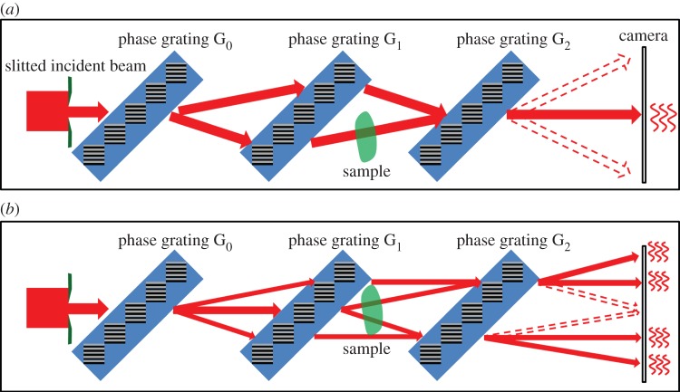
Two variants of the gBH interferometer. Both consist of a slit that limits the width of the incident beam, followed by three parallel gratings which are positioned in series and at equal spacing, then a gap and the X-ray camera. In variant (a) the first and third diffraction gratings have half the line density as that of the second grating. A pair of balanced diffraction pathways are represented by solid arrows. Other diffracted beams are represented by dotted arrows. Multiple diffraction pathways result in a number of separated diffraction bands on the camera. The pair of balanced paths interfere with each other to produce intensity fringes at the central band. When a sample intersects one or both of the interfering paths, it causes different phase shifts among them resulting in changes of the interference fringes. In variant (b) all three diffraction gratings have the same period. Two pairs of mutually balanced pathways are represented by solid arrows, which results in interference fringes in four diffraction bands on the camera. Variant (b) is realized in our experiment. (Online version in colour.)
3. Description of the grating Bonse–Hart interferometer
The basic configuration of the gBH interferometer is illustrated in figure 1a. It consists of a slit that limits the width of the incident beam, followed by three parallel and equally spaced diffraction gratings, then some distance down the beam by the X-ray camera. We first consider a parallel incident beam, which is diffracted by the first grating of period 2P into two beams. These are further diffracted by the second grating of period P into four beams. Two of the four merge at the third grating of period 2P. Each is further diffracted by the third grating. The multiple diffracted beams are allowed to propagate for sufficient distance such that the different diffraction orders are separated at the camera. As illustrated in figure 1a, there exists a pair of diffracted beams that co-propagate from the third grating to the camera. They interfere with each other to produce intensity fringes if the gratings are slightly misaligned with each other. It has been shown theoretically and verified experimentally [18] that the pair of diffraction paths are always balanced regardless of the X-ray energy or the angle of the incident beam. They maintain mutual coherence under a polychromatic and divergent source. On the camera plane, there are the foot prints of several other diffracted beams besides the coherent pair. By limiting the width of the incident beam and its angular divergence, the foot prints of different diffraction orders are separated on the camera plane. The result is distinct diffraction bands in the acquired image. The pair of coherent paths create interference fringes in the central band [18].
A variant configuration of the gBH interferometer is shown in figure 1b, where all three gratings have the same period. In this configuration, there are several pairs of mutually balanced and coherent pathways. They produce several bands of interference fringes at the camera. This configuration was realized in our experiment.
The imaged object is placed near the central grating. Absolute phase images are obtained if the object intersects one of a pair of coherent paths. Absolute phase is the accumulated phase advance or delay of wave propagation through the object relative to air. For larger objects, the both paths pass through the object, but at two locations which are separated by a lateral distance d. This results in a differential phase image of Φ(r)−Φ(r−d), where d is the lateral beam separation.
The gBH interferometer was implemented on the 2-BM bending magnetic beamline of the Advanced Photon Source at Argonne National Laboratory, Lemont, IL, USA. The beam energy was set at 22.5 keV and 1.5% bandwidth. The intergrating distance and the distance between the third grating and the camera were all set to 65 cm. With 200 nm period gratings, the lateral separation of the diffracted beams over the intergrating distance was 179 μm.
Because only phase gratings are used in the gBH interferometer, a key requirement is that the different diffraction orders are laterally separated on the camera. This condition is met by limiting the width and angular divergence of the incident beam such that the total footprint of a diffraction order is less than the lateral separation between adjacent orders. As the beamline is highly collimated, only the width of the incident beam needed to be considered. The width of the slit was approximately 160 μm. Figure 2 shows the intensity pattern on the camera. It consists of distinct diffraction bands. Several bands contain intensity fringes as the result of interference between mutually coherent pathways.
Figure 2.
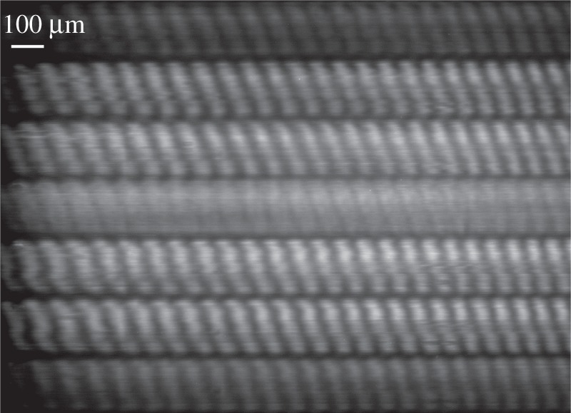
The intensity pattern on the camera in the gBH interferometer of variant (b) at X-ray photon energy of 22.5 keV. The lines of the gratings were oriented horizontally and the grating period was 200 nm. As illustrated in figure 1, the width of the incident beam was limited to 160 μm by a slit. Given the propagation distance of 65 cm between the last grating and the camera, multiple diffraction bands are separated in the image. Two pairs of balanced diffraction paths gave rise to the interference fringes in the +1, +2 and −1, −2 bands.
For phase retrieval, phase stepping was performed by moving the second grating vertically at increments of 20 or 40 nm. Each phase stepped set contained six images of 5 s exposure per image. Based on the known photon flux of the bending-magnetic beamline (8.7×10¹⁰ ph mm2 s−1), the accumulated surface exposure (skin) dose on the samples was 16 Gy. Image processing is done for a single diffraction band at a time. A Fourier analysis of the intensity fringes [19,20] was used to determine the actual position of the grating in each phase step, in order to cope with instrumental drifts. Once the phase-stepping positions are determined, a least-squares fitting routine was used to determine the phase of each pixel. A reference phase image was acquired without any samples to correct for background instrumental phase variations. No spatial integration of phase was performed.
4. Results
An example of phase imaging is shown in figure 3. The sample was two intersecting hairs. The horizontal hair was positioned within one of the two interfering beams, while the more vertical hair crossed both beams. The absolute phase of the horizontal hair was directly imaged. It exceeded π in the thicker part of the width, resulting in phase wrapping. Two phase images of the more vertical hair can be seen. The phase values of the two are opposite to each other and also wrapped. The appearance of the twin image is explained by the fact that this hair intersects both of the interfering beams. The segments in both beams appear in the phase image. As the phase image is the phase difference between the two beams, the two segments have opposite phase values. It is interesting to note that the appearance of twin images is similar to those seen in X-ray phase difference microscopy using a Fresnel zone plate and a transmission grating [21].
Figure 3.
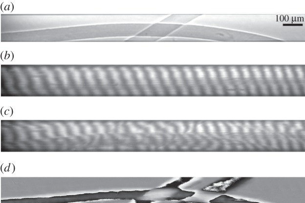
Images acquired from a sample of two intersecting hairs. Image (a) is a direct projection. The edges are enhanced by Fresnel diffraction over the distance between the sample and the camera. Image (b,c) are acquired with the gBH interferometer. They are from one of the diffraction bands on the camera that contain interference fringes. Image (b) is the reference without the sample. Image (c) was taken with the sample in place. During a phase-stepping process, a series of such images were taken while stepping the position of one of the gratings. From these images the phase map (d) was retrieved. Image (d) represents the absolute phase shift of the X-ray wave after propagating through the sample. Referring to figure 1, the more vertical hair intersected both of the interfering X-ray beams, resulting in twin images of opposite phase values in (d). Phase wrapping are seen in both hairs owing to the fact that the phase shifts exceeded π.
A more complex sample consisting of a number of polystyrene beads is shown in figure 4. The beads are distributed across both interfering beams. Depending on which beam crosses a bead, its phase value is either positive or negative. In some cases, the images of two beads overlap while each is physically in a separate beam. In these areas, the phases of the overlapping images substantially cancel each other.
Figure 4.
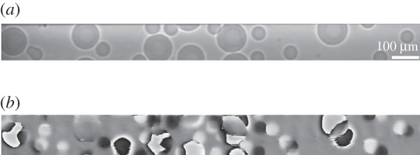
In this example, the sample consists of a distribution of polystyrene spheres. Image (a) is a direct projection. Edge enhancement is due to Fresnel diffraction over the distance between the sample and the camera. Image (b) is the phase image acquired by the gBH interferometer. The phase value of each bead can be positive or negative, depending on in which of the two interfering beams was it located. Also can be seen are overlapping phase images of two beads of opposite phases. These are from beads that were physically in separate beams.
To demonstrate phase-contrast imaging in biological samples, the body of a spider was imaged. The results are shown in figure 5. The spider was scanned in discrete steps, each step covering a band of 150 μm width. These bands were tied together to give contiguous images of the sample. In the phase image, twin images of the spider of opposite phase values appear. They are vertically displaced from each other by 141 μm, which equals the separation of the two interfering X-ray beams at the location of the spider. It can be seen that in the distal segments of the legs on the right the fluid had drained out, resulting in absolute phase values that are less than π and no phase wrapping. The left legs are intact. Their phase values are higher and phase wrapping occurs in all segments.
Figure 5.
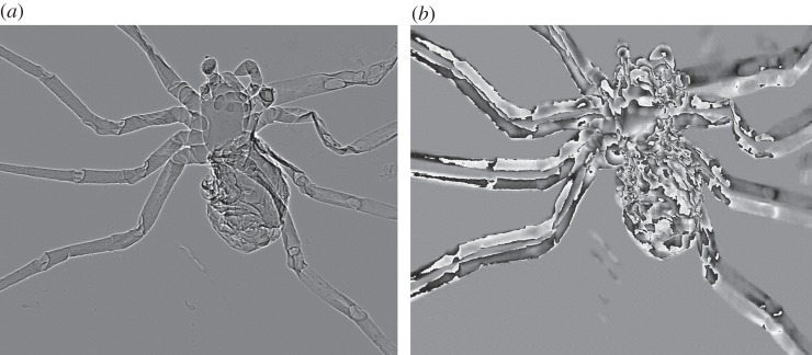
The projection (a) and phase (b) images of a spider. These were acquired in a number of steps. Each step covered a 150 μm wide band over the sample. The bands were tied together to give the full image. In the phase image (b), twin images of the spider of opposite phase values can be seen. They are vertically displaced from each other by 141 μm, which equals the separation of the two interfering X-ray beams at the location of the spider. The magnitude of the phase shifts exceeded π in many locations, resulting in frequent phase wrapping.
5. Conclusion
Several X-ray phase-contrast imaging techniques are successful extensions of classic interferometry concepts. Among them, the Bonse–Hart interferometer measures absolute phase shifts of wave propagation relative to air, which is the highest possible phase signal for interferometry methods. Although its sensitivity is higher than the Talbot grating interferometer, it does rely on Bragg diffraction in monolithic crystals, and therefore is highly selective of the energy of the X-ray beam for any given incident angle (Laue diffraction condition). We show that a gBH interferometer is feasible using gratings of sufficiently high line density. In this method, the gratings only need to modulate the phase of the wavefront, and therefore relieving the technical challenges of making absorption gratings. The key requirement of the method is that the grating period needs to be small enough to give a sufficiently large diffraction angle, which in conjunction with a limited width of the incident beam, causes the different diffraction orders to separate laterally on the detector.
The gBH interferometer is inherently achromatic as has been shown in the visible light analogue [18]. The requirement on spatial coherence of the source is determined by the trade-off between the width of the incident beam and its angular collimation. For example, in an interferometer of the specifications described above and operating at 22.5 keV, an X-ray beam of 0.06 milliradian angular dispersion and 80 μm width is sufficient to meet the requirement.
The synchrotron beamline of the experiment had a bandwidth of 1.5%, which was set by a multi-layer reflective monochrometer. This was narrow relative to an X-ray tube, although it was three orders of magnitude over the acceptance bandwidth set by the Laue diffraction condition in a classic BH interferometer. Thus, the experiment serves as a demonstration of the bandwidth expansion from the classic Bonse–Hart to the GBH interferometer.
A consequence of high phase sensitivity is the frequent occurrence of phase wrapping, a term that describes the mathematical discontinuities when the phase values reach 2π and cycle back to 0 radians. Phase unwrapping methods developed in other fields can be used to unwrap the X-ray phase images, although improvements and perhaps new methods may need to be developed to distinguish between physically abrupt phase changes at boundaries between compartments and mathematical phase jumps.
In the current version of the interferometer, a substantial part of the X-ray flux is absorbed in the silicon substrates of the gratings owing to the oblique incidence angle of the gratings. An area of future work is to fabricate gratings of more vertical incidence angles.
Acknowledgements
We are grateful to Dr Chian Liu and Dr Lahsen Assoufid of APS for their assistance with grating fabrication, to Cliff Sonnenbrot and Dr Alan Michelson of NIH for assistance with insect samples, to Dr Dumitru Mazilu of the NIH and Mr Pavel Shevchenko of APS for assistance with instrumentation. The grating substrates were made at the Nanofab Facility of NIST, USA.
Funding statement
The work was funded by the Division of Intramural Research, National Heart, Lung and Blood Institute, National Institutes of Health, under project no. HL006143-01. Use of the Advanced Photon Source at Argonne National Laboratory was supported by the US Department of Energy, Office of Science, Office of Basic Energy Sciences, under contract no. DE-AC02-06CH11357.
References
- 1.Cloetens P, Guigay JP, DeMartino C, Baruchel J, Schlenker M. 1997. Fractional Talbot imaging of phase gratings with hard X-rays. Opt. Lett. 22, 1059–1061. ( 10.1364/OL.22.001059) [DOI] [PubMed] [Google Scholar]
- 2.Clauser JF, inventor , assignee . Ultrahigh resolution interferometric x-ray imaging. 1998. Patent. U.S. patent 5,812,629. 22 September 1998. [Google Scholar]
- 3.David C, Nohammer B, Solak HH, Ziegler E. 2002. Differential x-ray phase contrast imaging using a shearing interferometer. Appl. Phys. Lett. 81, 3287–3289. ( 10.1063/1.1516611) [DOI] [Google Scholar]
- 4.Momose A. 2003. Phase-sensitive imaging and phase tomography using X-ray interferometers. Opt. Expr. 11, 2303–2314. ( 10.1364/OE.11.002303) [DOI] [PubMed] [Google Scholar]
- 5.Weitkamp T, Diaz A, David C, Pfeiffer F, Stampanoni M, Cloetens P, Ziegler E. 2005. X-ray phase imaging with a grating interferometer. Opt. Expr. 13, 6296–6304. ( 10.1364/OPEX.13.006296) [DOI] [PubMed] [Google Scholar]
- 6.Pfeiffer F, Weitkamp T, Bunk O, David C. 2006. Phase retrieval and differential phase-contrast imaging with low-brilliance X-ray sources. Nat. Phys. 2, 258–261. ( 10.1038/nphys265) [DOI] [Google Scholar]
- 7.Talbot HF. 1836. LXXVI. Facts relating to optical science. No. IV. Philos. Mag. 9, 401–407. [Google Scholar]
- 8.Momose A, Kawamoto S, Koyama I, Hamaishi Y, Takai K, Suzuki Y. 2003. Demonstration of X-Ray Talbot interferometry. Jpn J. Appl. Phys. 2 Lett. 42, L866–L868. ( 10.1143/JJAP.42.L866) [DOI] [Google Scholar]
- 9.Engelhardt M, Kottler C, Bunk O, David C, Schroer C, Baumann J, Schuster M, Pfeiffer F. 2008. The fractional Talbot effect in differential x-ray phase-contrast imaging for extended and polychromatic x-ray sources. J. Microsc. Oxf. 232, 145–157. ( 10.1111/j.1365-2818.2008.02072.x) [DOI] [PubMed] [Google Scholar]
- 10.Bonse U, Hart M. 1965. An X-ray interferometer. Appl. Phys. Lett. 6, 155 ( 10.1063/1.1754212) [DOI] [Google Scholar]
- 11.Momose A, Fukuda A. 1995. Phase-contrast radiographs of nonstained rat cerebellar specimen. Med. Phys. 22, 375–379. ( 10.1118/1.597472) [DOI] [PubMed] [Google Scholar]
- 12.David C, Bruder J, Rohbeck T, Grunzweig C, Kottler C, Diaz A, Bunk O, Pfeiffer F. 2007. Fabrication of diffraction gratings for hard X-ray phase contrast imaging. Microelectron. Eng. 84, 1172–1177. ( 10.1016/j.mee.2007.01.151) [DOI] [Google Scholar]
- 13.Noda D, Tanaka M, Shimada K, Yashiro W, Momose A, Hattori T. 2008. Fabrication of large area diffraction grating using LIGA process. Microsyst. Technol. 14, 1311–1315. ( 10.1007/s00542-008-0584-5) [DOI] [Google Scholar]
- 14.Reznikova E, Mohr J, Boerner M, Nazmov V, Jakobs PJ. 2008. Soft X-ray lithography of high aspect ratio SU8 submicron structures. Microsyst. Technol. 14, 1683–1688. ( 10.1007/s00542-007-0507-x) [DOI] [Google Scholar]
- 15.Lynch SK, et al. 2012. Fabrication of 200 nm period centimeter area hard x-ray absorption gratings by multilayer deposition. J. Micromech. Microeng. 22, 105007 ( 10.1088/0960-1317/22/10/105007) [DOI] [PMC free article] [PubMed] [Google Scholar]
- 16.Kim JM, Cho IH, Lee SY, Kang HC, Conley R, Liu C, Macrander AT, Noh DY. 2010. Observation of the Talbot effect using broadband hard x-ray beam. Opt. Expr. 18, 24975–24982. ( 10.1364/OE.18.024975) [DOI] [PubMed] [Google Scholar]
- 17.Lynch SK, et al. 2013. Interferometric hard X-ray phase contrast imaging at 204 nm grating period. Rev. Sci. Instrum. 84, 013706 ( 10.1063/1.4788910) [DOI] [PMC free article] [PubMed] [Google Scholar]
- 18.Kemble CK, Auxier J, Lynch SK, Bennett EE, Morgan NY, Wen H. 2010. Grazing angle Mach–Zehnder interferometer using reflective phase gratings and a polychromatic, un-collimated light source. Opt. Expr. 18, 27481–27492. ( 10.1364/OE.18.027481) [DOI] [PMC free article] [PubMed] [Google Scholar]
- 19.Takeda M, Ina H, Kobayashi S. 1982. Fourier-transform method of fringe-pattern analysis for computer-based topography and Interferometry. J. Opt. Soc. Am. 72, 156–160. ( 10.1364/JOSA.72.000156) [DOI] [Google Scholar]
- 20.Wen H, Bennett E, Hegedus MM, Carroll SC. 2008. Spatial harmonic imaging of X-ray scattering—initial results. IEEE Trans. Med. Imaging 27, 997–1002. ( 10.1109/TMI.2007.912393) [DOI] [PMC free article] [PubMed] [Google Scholar]
- 21.Yashiro W, Takeda Y, Takeuchi A, Suzuki Y, Momose A. 2009. Hard-X-ray phase-difference microscopy using a fresnel zone plate and a transmission grating. Phys. Rev. Lett. 103, 180801 ( 10.1103/PhysRevLett.103.180801) [DOI] [PubMed] [Google Scholar]


