Abstract
Terahertz (THz) imaging provides cutting edge technique in biology, medical sciences and non-destructive evaluation. However, due to the long wavelength of the THz wave, the obtained resolution of THz imaging is normally a few hundred microns and is much lower than that of the traditional optical imaging. We introduce a sub-wavelength resolution THz imaging technique which uses the THz radiation generated by a femtosecond laser filament in air as the probe. This method is based on the fact that the femtosecond laser filament forms a waveguide for the THz wave in air. The diameter of the THz beam, which propagates inside the filament, varies from 20 μm to 50 μm, which is significantly smaller than the wavelength of the THz wave. Using this highly spatially confined THz beam as the probe, THz imaging with resolution as high as 20 μm (~λ/38 at 0.4 THz) can be realized.
Resolution enhancement of terahertz (THz) imaging is one of central concerns in the THz science and technology research. Because of the used long wavelength (λ1 THz = 300 μm), THz imaging's resolution is generally in the scale of millimetre. This constitutes a major obstacle for the application of THz imaging in bio-medical diagnosis and semiconductor device inspection since the characteristic scales of the interested samples are often much smaller than the wavelength of the THz wave1,2,3. Different approaches have been implemented to optimize the THz imaging resolution. M. Tounouchi and his collaborators have developed a laser THz emission microscopy (LTEM) system3. The system detects the actively excited THz signal by focusing femtosecond laser beam on the semiconductor device. The resolution of the system is determined by the focus size of the laser beam and is about several microns. Another type of method relies on the analogues of the scanning near-field optical microscopy (SNOM). A so-called dynamic aperture produced by a gating laser beam and a tapered metal tip with a small exit aperture have been used by X.-C. Zhang's group and S. Hunsche et al., respectively, to limit the size of the THz wave illuminated on the sample4,5. In both cases, the resulted resolution is a few tens microns. H.-T. Chen et al. further applied the apertureless SNOM by substituting the aperture with a sharp tip6. The reported resolution by this means is 150 nm. However, when applying SNOM, only small portion of the THz wave energy is used. For example, as mentioned in Ref. 6, it is about 0.5%.
Here, we report on a novel sub-wavelength THz imaging method via the femtosecond laser filament in air, which refers to the plasma channel created by a femtosecond laser pulse7. One of the impressive characteristics of this novel THz source is its exceptional high field strength. The reported maximum electric field strength of the THz pulse generated by the filamentation has reached 4.4 MV/cm with a compact table-top infrared femtosecond laser setup8. In order to further increase the strength of the THz wave, two-colour laser field pumping scheme is often chosen in the practice9,10,11. This new type THz source has received intense research interest recently7,8,9,10,11,12,13,14,15,16. Particularly, because via appropriate optical adjustment, one may locate the filament at a remote distance as far as a few hundred metres, THz remote sensing has been proposed by using this technique to overcome the strong diffraction and the energy attenuation due to water vapour absorption in air10,11.
In the present work, we have investigated the variation of the THz beam diameter along the filament during a two-colour laser pumping experiment. The results indicate that the THz beam diameter varies between 20 μm and 50 μm in the region where a filament, i.e., a plasma column, exists. By using this strongly confined THz beam as the illumination source, we demonstrate that a scanning THz imaging setup with sub-wavelength resolution down to 20 μm is promising. Since the illuminating THz beam's diameter is inherently much smaller than the peak wavelength of the generated THz pulse (~0.4 THz), neither a limiting aperture nor a scattering metal tip suggested in the conventional THz-SNOM is necessary. The sample does not need to be an active medium being able to generate THz, neither. Therefore, better performance in signal to noise ratio (SNR) could be prospected for our technique.
Results
THz sub-wavelength imaging by femtosecond laser filament
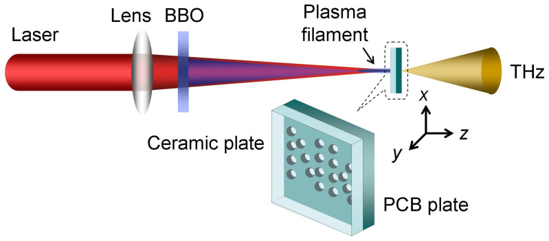
Fig. 1 schematically shows the experimental setup. Two-colour laser field (800 nm + 400 nm) was focused in air (f = 30 cm). A filament was then created at the vicinity of the focus. A single cycle THz pulse will be generated, and it is highly forwardly directional. The generated THz pulse was detected by a standard electric-optic sampling (EOS) setup, which has been described in detail elsewhere12. Since the beam diameter would be larger after the filament has ended13, sub-wavelength resolution THz imaging was carried out by inserting a sample in the middle of the filament. The sample used in our experiment was a PCB (printed circuit board) plate. Multiple through-holes were drilled on the plate. The thickness of the PCB plate is about 1.5 mm. Just in front of the PCB plate, a ceramic plate with a thickness of 0.8 mm was placed, in touch with the PCB plate. Because the ceramic plate is highly resistible to the high intensity femtosecond laser, it terminates the filament and excludes the laser damage of the sample. No laser transmitting or noticeable damage on the ceramic plate could be found during or after the experiment. The THz power transmission of the ceramic plate is about 50% (see Methods). The transmission could be further increased by using a thinner ceramic plate. On the other hand, the PCB plate has poor transmission of THz wave. Mainly the THz energy passing through the holes could be detected by EOS setup. The PCB plate and the ceramic plate were fixed on a two-axis translation stage and the THz image of the holes on the PCB plate was taken by moving the stage in the x-y plane (z axis is defined as the laser propagation direction). The step sizes were 100 μm and 100 μm along x and y axes, respectively. Note that full THz temporal waveforms have been recorded for each position.
Figure 1. Experimental setup for sub-wavelength resolution THz imaging.
A repetition rate of 1 kHz, central wavelength of 800 nm and duration of 50 fs Ti: sapphire laser pulse with energy of 1 mJ/pulse was focused by a f = 30 cm lens in air. The focused pump beam passed a 0.1-mm-thick Type I β-barium borate (BBO) crystal, creating plasma at the focus. THz emission from this plasma filament is utilized as the probe of THz imaging and measured by a standard EOS (electric-optic sampling) setup. The object to be imaged is a PCB (printed circuit board) plate with multiple through-holes drilled on the plate, inserted in the middle of the filament. An additional ceramic plate was put in front of the PCB plate to terminate the laser beam and exclude the laser ablation on the sample.
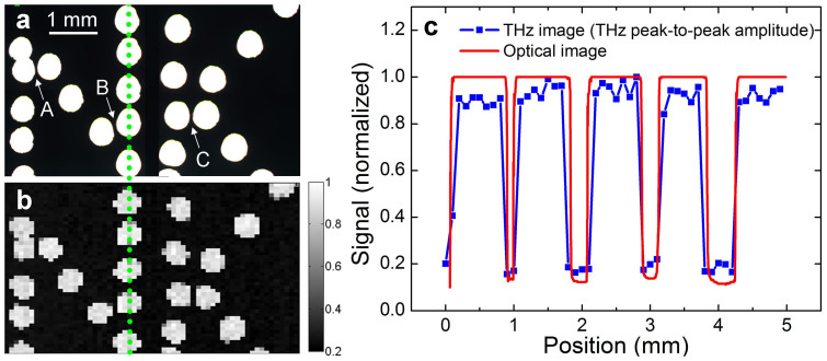
Fig. 2a illustrates the image of the multiple holes under optical microscope (resolution: 5 μm). The diameter of each hole is about 600 μm. The holes form two characters of “NK”, abbreviation for NanKai. The corresponding scanning THz image is displayed in Fig. 2b. Comparing Fig. 2a and 2b, no significant blurring effect could be noticed. In order to further highlight this trend, Fig. 2c plots the spatial profiles of a series of representative holes retrieved from both pictures along the green dotted line. The boundary of the hole identified in the THz imaging (blue solid squares) is as distinct as that of the optical imaging. Reminding ourselves that the peak wavelength of the THz pulse generated in our experiment is about 750 μm, which is even larger than the size of the holes on the PCB plate. However, Fig. 2 indicates that the minimum resolvable structure by THz imaging is less than 100 μm. For example, according to the optical image (Fig. 2a), three hole pitches pointed by arrow A, B and C have characterized widths of about 60 μm, 80 μm and 75 μm, respectively. And they can be clearly resolved by the THz imaging (Fig. 2b). Hence, the resolution of the obtained THz image by our method is much smaller than the THz pulse wavelength. It is interesting to mention that most of the previous THz sub-wavelength imaging experiments are performed on the surface of the targets3,6. In our experiment, the thickness of the PCB plate, which was used as the imaging target (please see Fig. 2), is about 1.5 mm. It hints that the effective length within which the diameter of the THz beam can be maintained to be more or less the same is about 1.5 mm.
Figure 2. Comparing THz image and optical microscope image.
(a) Optical microscope image of multiple through-holes on PCB (printed circuit board) plate. Each hole is about 600 μm in size. Arrow A, B and C point at three hole pitches with characterized widths of about 60 μm, 80 μm and 75 μm, respectively. (b) THz image of multiple through-holes on PCB plate. (c) Spatial profiles of a series of representative holes retrieved from (a) and (b) along the green dotted line, as red line and blue solid squares, respectively.
Resolution of THz imaging (Diameter of THz beam emission from femtosecond laser filament)
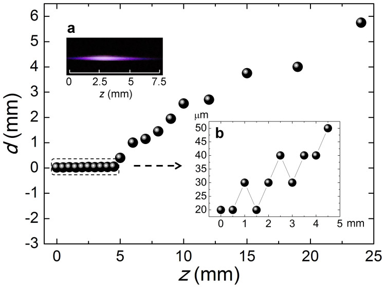
Efforts have been made to quantify the achievable resolution of the THz imaging by using the filamentation. The knife-edge method (KE) was applied to measure the THz beam diameter, which determines the THz imaging resolution in our experiment. During the experiment, we found that a PCB plate is indeed a good material to be used to cut the THz beam for two reasons: it is also highly resistible to the ablation of the intense femtosecond laser and has low transmission for THz wave (~4% power transmission). This time, a PCB plate was solely used and was scanned across the filament to perform the knife-edge measurement at different positions z. Note that z = 0 corresponds to the starting position where significant THz signal was able to be detected. Three representative measurements are demonstrated in Fig. 3 for z = 0 mm, 3 mm and 6 mm, respectively. All the three plots have been normalized to their maxima. The THz beam diameters d interpreted from Fig. 3 are d = 20 μm for z = 0 mm, d = 30 μm for z = 3 mm, and d = 1 mm for z = 6 mm, respectively. The obtained THz beam diameters d as a function of z is depicted in Fig. 4. THz beam diameter is initially 20 μm at z = 0. It slowly increases to 50 μm at z = 5 mm. Then a steep increase occurs between z = 5 mm and z = 6 mm (d = 1 mm). Afterwards, the THz beam diameter continuously increases to 6 mm when z = 24 mm. The results shown in Fig. 4 imply that the filament is sensitive to the PCB plate in our experiment. It could be attributed to the fact that when the PCB plate approaches the filament, it will block the energy reservoir, namely, the low intensity energy background surrounding the filament. Since the energy reservoir is the source to maintain the generation of the filament, the filament confinement will be terminated when the PCB plate approaches the filament14.
Figure 3. Three representative knife-edge measurements of THz beam diameter d.
(a) d = 20 μm at z = 0 mm. (b) d = 30 μm at z = 3 mm. (c) d = 1 mm at z = 6 mm. z axis corresponds to the laser propagation direction and z = 0 is defined as the starting position where significant THz signal was able to be detected.
Figure 4. THz beam diameter d as a function of z.
The insets (a) and (b) are side image of plasma filament and partially enlarged detail of d measurement results from z = 0 mm to z = 5 mm. z axis corresponds to the laser propagation direction and z = 0 is defined as the starting position where significant THz signal was able to be detected.
Considering that THz pulse generated in our experiment will consist of broadband frequencies9,10,11,12,13,15,16,17, we have also studied the frequency dependence of the THz beam diameters. Thus, fast Fourier transformations (FFT) have been performed for all the recorded THz waveforms. Based on the results, two representative frequencies, namely peak frequency fp and mean frequency fm have been investigated. The mean frequency was determined according to:
 |
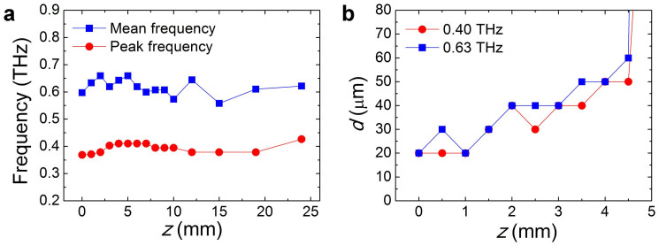
where f denotes the frequency and S(f) corresponds to the amplitude of the THz spectrum. The variations of the peak frequency and the mean frequency are depicted in Fig. 5a with respect to the propagation distances. Fig. 5a indicates that the peak frequency and the mean frequency are approximately 0.4 THz and 0.63 THz, respectively. Then, the knife-edge measurements demonstrated by Fig. 3 were carried out for the amplitudes of the THz spectra at these two frequencies. The outcome is illustrated in Fig. 5b. Similar trends like Fig. 4 could be seen in Fig. 5b for both fp and fm. According to Fig. 5b, a sub-wavelength resolution of λ/38 could be achieved at 0.4 THz.
Figure 5. Frequency dependence of the THz beam diameters d.
(a) Variations of peak frequency (fp, red solid circles) and mean frequency (fm, blue solid squares) with respect to the propagation distances z. (b) THz beam diameters d as a function of z at fp and fm, in both cases the trends are similar to Fig. 4.
THz wave guiding by femtosecond laser filament in air
What Fig. 4 impresses us most is that the THz pulse energy is spatially constrained inside a space which is much smaller than the wavelength. The jump of the curve in Fig. 4 taking place between z = 5 mm and z = 6 mm gives a hint that the THz wave is in fact strongly guided from z = 0 mm to z = 5 mm. Coincidentally, this region superposes with the zone where significant plasma, i.e. a filament, was produced during the filamentation. Fig. 4a presents a picture of the filament created in our experiment. It was taken by a digital camera set perpendicularly to the z axis. In view of the overlapped locations of the THz wave guiding and plasma generation, we have reason to believe that a THz waveguide is created inside the filament. Note that wave guiding by plasma filaments has been proposed and demonstrated at microwave frequencies18,19,20,21,22. Our results imply that similar guiding phenomenon may also occur at THz band. It is this waveguide that strongly confines the THz energy into a region with only a few ten microns in diameter. And this phenomenon makes a novel sub-wavelength THz imaging technique feasible as we have demonstrated.
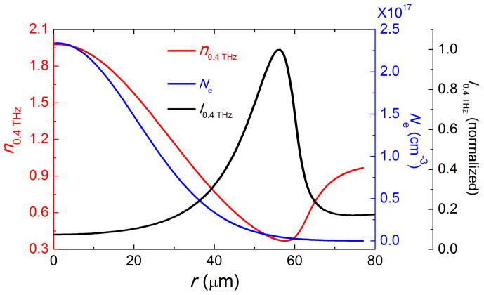
In order to confirm that creation of a THz waveguide by the filamentation, we have estimated the plasma density profile created by the two-colour laser field and calculated the corresponding refractive index distribution as well. Following Ref. 15, we take the peak intensity of the fundamental beam and the second harmonic beam at focus as Iω = 1 × 10¹⁴ W/cm2 and I2ω = 2 × 10¹³ W/cm2, respectively. Assuming two-colour pulses are in phase (ϕω−2ω = 0), the obtained peak plasma density is Ne = 2.34 × 1017 cm−3 according to the static tunnelling ionization rate described in Ref. 9 and Methods. Then the plasma distribution at the focus is considered as a Gaussian whose full width at half maximum (FWHM) is about 50 μm according to the result of side CCD image of the filament (not shown). Therefore, the refractive index distribution at the focus is given by
 |
where ωp indicates plasma frequency (in SI units):
 |
Ne denotes the number density of electrons, e represents the electric charge, me indicates the effective mass of the electron and ε0 is the permittivity in vacuum. v ~ 1 THz corresponds to the typical electron collision frequency inside filament16. The calculated radial distributions of Ne and n0.4 THz are shown in Fig. 6, as blue line and red line, respectively. One can see a refractive index dip appears at the vicinity of r = 55 μm.
Figure 6. Distributions of plasma density Ne, refractive indices n0.4 THz and mode field intensity I0.4 THz as a function of r.
Ne distribution (blue line) is considered as a Gaussian, with FWHM (full width at half maximum) of 50 μm. The corresponding n0.4 THz distribution (red line) has a minimum around r = 55 μm. Mode field intensity distribution I0.4 THz (black line) is retrieved from Fig. 7b along the white line and its maximum is also located at about r = 55 μm.
Then, we calculate the THz wave eigenmodes given by the refractive index distribution mentioned above. The calculation was carried out by the full-vector finite-element method (FEM) with the commercial software COMSOL Multiphysics. In our FEM model, quadratic triangular elements with a maximum size 1 μm and the perfectly matched layers (PMLs) at the boundary of air area were applied. The doublet degenerated modes localized in the filament area are found in our simulation. Fig. 7 shows the intensity profiles (z-component of the Poynting vector) and electric field vector of these modes at 0.2 THz, 0.4 THz and 0.6 THz, respectively. Since the fields are identical after a rotation of π/2 radian, only one of the doublet degenerated modes is illustrated. As shown in Fig. 7, the intensity fields are localized in a circular region with diameters of about 130 μm, 110 μm and 105 μm at 0.2 THz, 0.4 THz and 0.6 THz, respectively. The mode profiles given by Fig. 7 agree with recent reports that the emissions pattern in two-colour THz generation processes is a conical wave13,23,24,25. Particularly, M. Clerici et al. have pointed out that the THz beam is Bessel shaped and the self-healing properties of the Bessel beam would not play a significant role in KE experiment as demonstrated by Ref. 25. Fig. 7 also indicates that the electric field vector is nearly radial polarization for these modes. Note that the calculation is made for the focus, where the plasma density and diameter may be strongest. The actual diameters of THz mode fields could be smaller than 100 μm along the filament. To compare with the refractive index distribution, the mode field intensity at 0.4 THz along the white line in Fig. 7b is also shown in Fig. 6 (black line). At 0.4 THz, the mode field is strongly confined in a sub-wavelength region, and the maximum light field is located at the refractive index dip.
Figure 7. Three typical THz eigenmodes around the filament area.
One of the doublet degenerated modes at (a) 0.2 THz, (b) 0.4 THz and (c) 0.6 THz with z-component of the Poynting vector (colour) and electric vector (arrows). The mode field intensity along the white line in (b) is shown in Fig. 6 as black line.
It is worth mentioning that in our simulation scheme, the ω − 2ω phase shift ϕω−2ω mainly affects the generated peak plasma density Ne. When ϕω−2ω = 0, Ne is maximum; Ne would reach a minimum value of 1.76 × 1017 cm−3. Similar mode distribution can be obtained by assuming Ne = 1.76 × 1017 cm−3 in our simulation. Therefore, the ω − 2ω phase shift does not play a significant role in our simulation of the mode distribution.
Discussion
The calculation of Fig. 6 is made based on the assumption that the plasma density distribution follows Gaussian. However, it might not be totally fulfilled due to the strong space-time self-transformation occurred during the filamentation. This may explain the quantitative difference of the THz beam diameters shown in Fig. 4 and 6. Furthermore, since a conventional THz-TDS (time domain spectroscopy) setup is implemented as the detection method, a complete THz pulse waveform has to be acquired by scanning the optical delay in order to get the peak-to-peak amplitude of the THz pulse. Though both amplitude and phase information could be retrieved, it is quite time consuming. For example, a measurement of Fig. 2b costs about 10 hours. If one was only interested in the power transmission, the measurement could be significantly speeded up by using THz power meter instead of TDS system.
Besides, M. Peccianti et al. have recently pointed out that special caution need to be paid to the THz field measurement by combining knife-edge method with time domain spectroscopy26. They have found that for a THz source with sub-wavelength dimension, the coupling between x, y and t coordinates has to be taken into account in order to reconstruct the THz field from KE + TDS system. In fact, M. Clerici et al. have demonstrated recently that for a conical beam, though the KE measurement could not resolve the spatial profile with fine details, it is still capable to give the essential information about the overall THz beam diameter25. In addition, Ref. 26 has suggested that the space-time coupling mainly affects the spatial symmetry of the measured THz beam profile, but does not alert the beam diameter significantly. Therefore, when the retrieving of the fine structure of the THz beam profile with high accuracy is not the central interest, KE + TDS detection remains reliable to measure the overall beam diameter.
Furthermore, by using some other detection techniques, broader detection bandwidth could be achieved as compared with our TDS system15,27,28,29. Thus, though the proof-of-principle of the sub-wavelength imaging method is reported in the present work for the low frequencies, the investigation about its application at high frequency range has been planned for future systemic study in terms of various experimental parameters, including pump laser energy30, pulse duration31, laser polarization32, laser wavelength8, gas species16, gas pressure33 and detection technique28,29,30,34,35, etc. Nevertheless, it could be foreseen that if adopting broad bandwidth detection methods, such as ABCD (Air-Breakdown Coherent Detection)27, sub-wavelength THz imaging technique demonstrated here may possess exceptional spectral analysis ability simultaneously.
In summary, we report on a novel technique to realize THz imaging with sub-wavelength resolution. Our method relies on the THz wave generated by a femtosecond laser filament in air. Because of the radial inhomogeneous distribution of refractive index given by the plasma density inside the filament, a THz waveguide is created. This plasma THz waveguide strongly confines the THz radiation into a region with a size of only a few tens micron. Using this filamentation generated THz source as a probe, the achievable THz imaging resolution can be as high as 20 μm (~λ/38 at 0.4 THz) while retaining the exceptional high THz field strength achieved by the two-colour laser pumping experiment. Because of this advantage, it could be expected that without dramatic sacrifice the signal contrast, the THz imaging resolution could be further improved by inserting additional aperture with even smaller opening like SNOM. Moreover, K. Wang et al. have recently demonstrated that an optical super-resolution of 40 μm has been achieved when a target, which was placed at a distance of 4.5 m away from the laser output, was illuminated by the filament generated in air36. The combination of the two concepts, namely, the reported super-resolution THz imaging and the filament assisted remote detection10,11,36, may open a new way to realize sub-wavelength THz remote imaging.
Methods
Measurement of THz pulse waveform
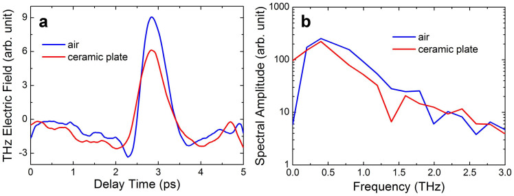
The experimental setup is that a 1 kHz, 800 nm, 50 fs Ti: sapphire laser pulse was split into two paths. One was the pump beam and the other was used as the probe of EOS. The energy of the pump beam was about 1 mJ/pulse and focused by a f = 30 cm lens. The thickness of the inserted Type I phase matching BBO crystal was 0.1 mm. A filament was induced by the two-colour laser pulse at the focus. And the exiting THz pulse from the filament was first collimated by an off-axis parabolic mirror (D = 50 mm, f = 100 mm), then focused by another identical parabolic mirror onto a 1-mm-thick ZnTe crystal. Throughout the experiment, it has been carefully verified that the parabolic mirrors are bigger enough to collect all the emitted THz energy from the filament when performing KE method. The probe beam was combined with THz pulse by a Pellicle beam splitter, performing EOS measurement. Representative experimentally recorded THz electric field waveforms and the corresponding THz spectra are shown in Fig. 8a and 8b, respectively. It is worth mentioning that if the detection area of the EOS system is too small, when KE method is applied, the fraction of the power collected by the detector may vary with the position of the blade. In order to rule out this effect, the beam splitter was set between the focusing parabolic mirror and the ZnTe crystal in our experiment. Hence, only the THz beam was focused in the detection system, while the 800 nm probe beam retained its initial diameter (~8 mm)12,37. In addition, the detector diameters of the two identical photodiodes used for balanced detection in our EOS system were 5 mm, yielding to a large enough effective detection area to cover the whole focused THz beam inside the ZnTe crystal25.
Figure 8. THz electric field waveforms and the corresponding THz spectra.
(a) Measured THz pulse waveforms in air (blue line) and after transmission through the ceramic plate (red line). (b) The corresponding THz spectra, whose peak amplitudes are both at 0.4 THz.
Calculation of plasma density
The ionization rate R(t) could be commonly described by the static tunnelling model in the form of Ref. 9:
 |
where
 |
is the electric field in atomic units and  ,
,  ,
,  . ωa corresponds to the atomic frequency unit, rH = Uion/UH indicates the ionization potential of the gas molecules under consideration relative to that of hydrogen (UH = 13.6 eV) and κ = (4πε0)−1. In the calculations, the air is considered as being composed of 78% nitrogen and 22% oxygen with Uion, N2 = 15.6 eV and Uion, O2 = 12.1 eV. Hence, the electron density Ne(t) in air is given by:
 |
where
 |
 and
and  denote the neutral density of nitrogen and oxygen, respectively. Since the laser intensity at the focus is not precisely known, it is assumed that the peak amplitude of the fundamental beam (
 ) in eq. (5) is 2.75 × 10⁸ V/cm, corresponding to a laser intensity of Iω = 1 × 10¹⁴ W/cm2 at the focus, calculated by
 |
where η = 377Ω is the impedance. The peak amplitude of the second harmonic beam ( ) is assumed to be 1.23 × 10⁸ V/cm, corresponding to I2ω = 2 × 10¹³ W/cm2.
Author Contributions
W.L. and Y.C. planned and designed the experiments. J.Z., W.C. and L.G. performed the experiments. J.Z. and J.Y. analyzed the data. Z.W. performed the numerical simulation. Z.X. supervised the project. All authors participated in the discussion of the results and the writing of the manuscript.
Acknowledgments
This work is financially supported by National Basic Research Program of China (2014CB339802, 2011CB808100) and National Natural Science Foundation of China (11174156). W.L. acknowledges the support of the open research funds of State Key Laboratory of High Field Laser Physics, Shanghai Institute of Optics and Fine Mechanics (SIOM).
References
- Tonouchi M. Cutting-edge terahertz technology. Nat. Photonics 1, 97–105 (2007). [Google Scholar]
- Zhang X. C. Terahertz wave imaging: horizons and hurdles. Phys. Med. Biol. 47, 3667 (2002). [DOI] [PubMed] [Google Scholar]
- Inoue R., Uchida N. & Tonouchi M. Scanning probe laser terahertz emission microscopy system. Jpn. J. Appl. Phys. 45, L824–L826 (2006). [Google Scholar]
- Chen Q., Jiang Z., Xu G. X. & Zhang X. C. Near-field terahertz imaging with a dynamic aperture. Opt. Lett. 25, 1122–1124 (2000). [DOI] [PubMed] [Google Scholar]
- Hunsche S., Koch M., Brener I. & Nuss M. C. THz near-field imaging. Opt. Commun. 150, 22–26 (1998). [Google Scholar]
- Chen H. T., Kersting R. & Cho G. C. Terahertz imaging with nanometer resolution. Appl. Phys. Lett. 83, 3009–3011 (2003). [Google Scholar]
- D Amico C. et al. Conical forward THz emission from femtosecond-laser-beam filamentation in air. Phys. Rev. Lett. 98, 235002 (2007). [DOI] [PubMed] [Google Scholar]
- Clerici M. et al. Wavelength scaling of terahertz generation by gas ionization. Phys. Rev. Lett. 110, 253901 (2013). [DOI] [PubMed] [Google Scholar]
- Roskos H. G., Thomson M. D., Kreβ M. & Löffler T. Broadband THz emission from gas plasmas induced by femtosecond optical pulses: From fundamentals to applications. Laser Photonics Rev. 1, 349–368 (2007). [Google Scholar]
- Wang T. J. et al. Toward remote high energy terahertz generation. Appl. Phys. Lett. 97, 111108 (2010). [Google Scholar]
- Liu J., Dai J., Chin S. L. & Zhang X. C. Broadband terahertz wave remote sensing using coherent manipulation of fluorescence from asymmetrically ionized gases. Nat. Photonics 4, 627–631 (2010). [Google Scholar]
- Zhang Y. et al. Non-radially polarized THz pulse emitted from femtosecond laser filament in air. Opt. Express 16, 15483–15488 (2008). [DOI] [PubMed] [Google Scholar]
- Zhong H., Karpowicz N. & Zhang X. C. Terahertz emission profile from laser-induced air plasma. Appl. Phys. Lett. 88, 261103–261103 (2006). [Google Scholar]
- Liu W. et al. Experiment and simulations on the energy reservoir effect in femtosecond light filaments. Opt. Lett. 30, 2602–2604 (2005). [DOI] [PubMed] [Google Scholar]
- Kim K. Y., Glownia J. H., Taylor A. J. & Rodriguez G. Terahertz emission from ultrafast ionizing air in symmetry-broken laser fields. Opt. Express 15, 4577–4584 (2007). [DOI] [PubMed] [Google Scholar]
- Kim K. Y., Taylor A. J., Glownia J. H. & Rodriguez G. Coherent control of terahertz supercontinuum generation in ultrafast laser–gas interactions. Nat. Photonics 2, 605–609 (2008). [Google Scholar]
- Houard A., Liu Y., Prade B., Tikhonchuk V. T. & Mysyrowicz A. Strong enhancement of terahertz radiation from laser filaments in air by a static electric field. Phys. Rev. Lett. 100, 255006 (2008). [DOI] [PubMed] [Google Scholar]
- Chekalin S. V. & Kandidov V. P. From self-focusing light beams to femtosecond laser pulse filamentation. Phys. Usp. 56, 123 (2013). [Google Scholar]
- Askar'yan G. A. Waveguide properties of a tubular light beam. Soviet Phys. JETP 28, 732 (1969). [Google Scholar]
- Valuev V. V. et al. Plasma channels formed by a set of filaments as a guiding system for microwave radiation. J. Commun. Technol. Elect. 55, 208–214 (2010). [Google Scholar]
- Dormidonov A. E., Valuev V. V., Dmitriev V. L., Shlenov S. A. & Kandidov V. P. Laser filament induced microwave waveguide in air. In Proc. SPIE 6733, 67332S (2007). [Google Scholar]
- Châteauneuf M., Payeur S., Dubois J. & Kieffer J. C. Microwave guiding in air by a cylindrical filament array waveguide. Appl. Phys. Lett. 92, 091104–091104 (2008). [Google Scholar]
- You Y. S., Oh T. I. & Kim K. Y. Off-axis phase-matched terahertz emission from two-color laser-induced plasma filaments. Phys. Rev. Lett. 109, 183902 (2012). [DOI] [PubMed] [Google Scholar]
- Blank V., Thomson M. D. & Roskos H. G. Spatio-spectral characteristics of ultra-broadband THz emission from two-colour photoexcited gas plasmas and their impact for nonlinear spectroscopy. New J. Phys. 15, 075023 (2013). [Google Scholar]
- Clerici M. et al. CCD-based imaging and 3D space–time mapping of terahertz fields via Kerr frequency conversion. Opt. Lett. 38, 1899–1901 (2013). [DOI] [PubMed] [Google Scholar]
- Peccianti M. et al. Exact reconstruction of THz sub-λ source features in knife-edge measurements. IEEE J. Sel. Top. Quantum Elect. 19, 8401211 (2013). [Google Scholar]
- Dai J., Xie X. & Zhang X. C. Detection of broadband terahertz waves with a laser-induced plasma in gases. Phys. Rev. Lett. 97, 103903 (2006). [DOI] [PubMed] [Google Scholar]
- Wu Q. & Zhang X. C. 7 terahertz broadband GaP electro-optic sensor. Appl. Phys. Lett. 70, 1784–1786 (1997). [Google Scholar]
- Thomson M. D., Blank V. & Roskos H. G. Terahertz white-light pulses from an air plasma photo-induced by incommensurate two-color optical fields. Opt. Express 18, 23173–23182 (2010). [DOI] [PubMed] [Google Scholar]
- Oh T. I. et al. Intense terahertz generation in two-color laser filamentation: energy scaling with terawatt laser systems. New J. Phys. 15, 075002 (2013). [Google Scholar]
- Bartel T., Gaal P., Reimann K., Woerner M. & Elsaesser T. Generation of single-cycle THz transients with high electric-field amplitudes. Opt. Lett. 30, 2805–2807 (2005). [DOI] [PubMed] [Google Scholar]
- Xie X., Dai J. & Zhang X. C. Coherent control of THz wave generation in ambient air. Phys. Rev. Lett. 96, 075005 (2006). [DOI] [PubMed] [Google Scholar]
- Rodriguez G. & Dakovski G. L. Scaling behavior of ultrafast two-color terahertz generation in plasma gas targets: energy and pressure dependence. Opt. Express 18, 15130–15143 (2010). [DOI] [PubMed] [Google Scholar]
- Karpowicz N. et al. Coherent heterodyne time-domain spectrometry covering the entire “terahertz gap”. Appl. Phys. Lett. 92, 011131–011131 (2008). [Google Scholar]
- Babushkin I. et al. Ultrafast spatiotemporal dynamics of terahertz generation by ionizing two-color femtosecond pulses in gases. Phys. Rev. Lett. 105, 053903 (2010). [DOI] [PubMed] [Google Scholar]
- Wang K. et al. Remote sub-diffraction imaging with femtosecond laser filaments. Opt. Lett. 37, 1343–1345 (2012). [DOI] [PubMed] [Google Scholar]
- Zhang Y. et al. Portraying polarization state of terahertz pulse generated by a two-color laser field in air. Opt. Lett. 34, 2841–2843 (2009). [DOI] [PubMed] [Google Scholar]


