

Abstract
We sought to compare the safety and accuracy of a new free-hand pedicle screw placement technique to that of the conventional technique. One hundred fifty-three consecutive adult patients with simple fracture in the thoracic or/and lumbar spine were alternately assigned to either the new free-hand or the conventional group. In the new free-hand technique group, preoperative computerized tomography (CT) images were used to calculate the targeted medial-lateral angle of each pedicle trajectory and the pedicle screw was inserted perpendicular to the correspond-ing supraspinal ligament. In the conventional technique group, the medial-lateral and cranial-caudal angle of each pedicle trajectory was determined by intraoperatively under fluoroscopic guidance. The accuracy rate of pedicle screw placement, the time of intraoperative fluoroscopy, the operating time and the amount of blood loss during operation were respectively compared. All screws were analyzed by using intraoperative radiographs, intraoperative triggered electromyography (EMG) monitoring data, postoperative CT data and clinical outcomes. The accuracy rate of pedicle screw placement in the new free-hand technique group and the conventional technique group was 96.3% and 94.2% (P < 0.05), respectively. The intraoperative fluoroscopy time of the new technique group was less than that of the conventional technique group (5.37 seconds vs. 8.79 seconds, P < 0.05). However, there was no statistical difference in the operating time and the amount of blood loss during operation (P > 0.05). Pedicle screw placement with the free-hand technique which keeps the screw perpendicular to the supraspinal ligament is an accurate, reliable and safe technique to treat simple fracture in the thoracic or lumbar spine.
Keywords: spine fracture, pedicle screw placement, radiation exposure, supraspinal ligament, anatomy reference
INTRODUCTION
Pedicle screw is widely used in the treatment of degenerative, traumatic and developmental conditions of the spine as it achieves excellent biomechanical fixation and deformity correction[1]. Due to unique neurologic and vascular anatomy of the spinal canal, techniques to optimize screw placement and confirm intraosseous screw position are being developed to create an environment as safe as possible for pedicle screw placement[2]–[5]. The accurate placement of these screws within the bony confines of the pedicle is crucial to avoid loss of fixation and prevent potentially serious neurovascular injury[6],[7]. Critical intraoperative assessment of pedicle screw placement using intraoperative fluoroscopy and conventional radiography in the posteroanterior and lateral projections is an essential step in preventing possible neurologic and vascular complications[8]. For insertion of pedicle screws into the right place, they should be placed at proper medial-lateral and cranial-caudal angles according to the corresponding entry points. Techniques of pedicle screw placement in the thoracic, lumbar and sacral spine are traditionally based on a morphometric understanding of the posterior elements according to clues from both intraoperative imaging and tactile feedback. Techniques of screw placement vary among surgeons depending on training, experience and resources available at the time of surgery[9]. A number of computerized tomography (CT) and fluoroscopy-based navigation systems have been developed with demonstrated ability to increase screw accuracy, decrease radiation exposure and reduce operative times[10],[11]. Unfortunately, these systems have not seen widespread adoption as they require time-consuming planning and invasive fixation of a reference arm, and they are unable to compensate for positional changes and are expensive capital investments[11]–[18].
The purpose of this study was to compare the supraspinal ligament-based new free-hand technique with the fluoroscopy-based conventional technique in the placement of pedicle screws.
MATERIALS AND METHODS
Anatomic relationship
One hundred normal thoracolumbar magnetic resonance (MR) images at the middle sagittal plane were recruited from the imaging department of the authors' affiliated hospital (100 patients, including 47 males and 53 females, aged from 16 to 78 years with a median age of 48 years). Picture archiving and communication system (PACS) was performed to detect angle relationship between the upper vertebral endplate and the supraspinal ligament from MRI images (Fig. 1). MRI films at the middle sagittal plane displayed the supraspinal ligament clearly behind the spinous process. If the supraspinal ligament was not clear, the angle between the line parallel to the surface of the upper vertebral endplate and the line connecting the upper and lower spinous process trailing edge was measured instead. Images with spine fracture, spondylolisthesis, tumor, severe degeneration and deformity were excluded. After measurements and analyses, the angle from T1 to L4 was about 90°, but approximately 80° with that of L5 (Table 1). It was theoretically feasible, that from T1 to L4, if pedicle screws were placed perpendicular to the supraspinal image, they would be parallel to the surface of the upper endplate (Fig. 2 and 3).
Fig. 1. PACS analysis of MRI image.
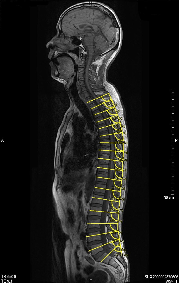
The angle between the upper vertebral endplate and the surface of the supraspinous ligament is measured from T1 to L5 by the picture archiving and communication system (PACS).
Table 1. The angle between the vertebral upper endplate and the the surface of the supraspinous ligament.
| Centrum | Mean | Stand Error | 95%CI | Min | Max | Difference with 90 |
|||
| Mean | 95%CI | ||||||||
| T1 | 91.12 | 0.13 | (90.86 | 91.38) | 88.73 | 93.73 | 1.12 | (0.86 | 1.38) |
| T2 | 90.33 | 0.12 | (90.09 | 90.57) | 86.42 | 93.42 | 0.33 | (0.09 | 0.57) |
| T3 | 90.41 | 0.11 | (90.20 | 90.62) | 87.79 | 94.18 | 0.41 | (0.20 | 0.62) |
| T4 | 89.91 | 0.10 | (89.72 | 90.10) | 87.15 | 91.97 | -0.09 | (-0.28 | 0.10) |
| T5 | 89.64 | 0.09 | (89.46 | 89.82) | 87.23 | 91.18 | -0.36 | (-0.54 | -0.18) |
| T6 | 89.86 | 0.10 | (89.67 | 90.05) | 86.90 | 92.89 | -0.14 | (-0.33 | 0.05) |
| T7 | 90.21 | 0.09 | (90.04 | 90.38) | 87.30 | 92.18 | 0.21 | (0.04 | 0.38) |
| T8 | 90.58 | 0.09 | (90.40 | 90.76) | 88.60 | 93.20 | 0.58 | (0.41 | 0.75) |
| T9 | 90.62 | 0.14 | (90.34 | 90.90) | 80.37 | 93.93 | 0.62 | (0.34 | 0.90) |
| T10 | 90.36 | 0.10 | (90.17 | 90.55) | 88.08 | 93.77 | 0.36 | (0.17 | 0.55) |
| T11 | 90.45 | 0.08 | (90.29 | 90.61) | 88.00 | 92.94 | 0.45 | (0.29 | 0.61) |
| T12 | 90.86 | 0.09 | (90.68 | 91.04) | 88.80 | 94.76 | 0.86 | (0.68 | 1.04) |
| L1 | 90.76 | 0.10 | (90.57 | 90.95) | 88.34 | 93.27 | 0.76 | (0.57 | 0.95) |
| L2 | 90.57 | 0.11 | (90.36 | 90.78) | 88.00 | 95.32 | 0.57 | (0.36 | 0.78) |
| L3 | 90.14 | 0.10 | (89.94 | 90.34) | 87.81 | 92.58 | 0.14 | (-0.06 | 0.34) |
| L4 | 89.42 | 0.13 | (89.16 | 89.68) | 86.44 | 92.86 | -0.58 | (-0.84 | -0.32) |
| L5 | 79.79 | 0.38 | (79.04 | 80.54) | 68.22 | 88.77 | -10.21 | (-10.59 | -9.47) |
Note: Data of means, stand error, min, max, and 95% confidence intervals are statistical data of the angle between the vertebral upper end plate and the surface of the supraspinous ligament from T1 to L5, with its 95% confidence intervals with 90.
Fig. 2. Surgical simulation.
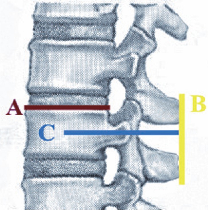
It is theoretically feasible that from T1 to L4, if the pedicle screws (blue, line C) are placed perpendicular to the supraspinous ligament (yellow, line B), the pedicle screws will be parallel to the surface of the upper endplate (red, line A).
Fig. 3. The pedicle screws are placed parallel to the surface of the upper vertebral endplate.
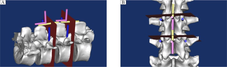
The pedicle screw (blue cylinder) should be placed parallel to the surface of the upper vertebral endplate (red plane). However, the upper vertebral endplate is not visible during surgery. We can just insert the pedicle screws at 90° with the supraspinous ligament (yellow cylinder) with the help of an “L” shaped measuring device (pink cylinder). A: Lateral view. B: Posteroanterior view.
Patients
From July 2005 to January 2012, 153 adult patients with simple fracture (AO classification of spine fractures: A1, A2, A3 and B1) in the thoracic and/or lumbar spine were enrolled in this study. Patient enrollment was limited to patients whose age was between 16 and 80 years and whose preoperative diagnoses required only posterior pedicle screw fixation in the thoracic and/or lumbar spine. Patients were excluded from study participation if they underwent previous instrumented surgery, and suffered from nerve root, spinal cord, supraspinal ligament and severe combined injury, spinal deformity, serious spine degeneration or serious osteoporosis (T < -2.5) at fractured level(s). After providing written informed consents, patients were assigned to treatment groups according to the order of enrollment. In the conventional group, 76 patients with a median age of 43.7 years (42 males and 34 females, and aged from 22 to 72 years) received conventional intraoperative fluoroscopy (referred to hereafter as the “conventional technique”). In the new free-hand technique group, 77 patients with a median age of 41.2 years (48 males and 29 females, and aged from 16 to 77 years) were treated with the new method of free-hand technique (referred to hereafter as the “new free-hand technique”) (Table 2).
Table 2. Comparison between new free hand group and conventional group on fractured vertebrae and inserted pedicle screws.
| Fractured vertebrae |
Inserted pedicle screws |
||||
| New free-hand group | Conventional group | New free-hand group | Conventional group | ||
| T1 | 0 | 0 | 2 | 0 | |
| T2 | 0 | 0 | 4 | 2 | |
| T3 | 2 | 1 | 2 | 6 | |
| T4 | 2 | 2 | 10 | 6 | |
| T5 | 3 | 2 | 10 | 12 | |
| T6 | 3 | 4 | 16 | 8 | |
| T7 | 4 | 3 | 12 | 8 | |
| T8 | 3 | 5 | 14 | 8 | |
| T9 | 3 | 4 | 18 | 20 | |
| T10 | 6 | 6 | 18 | 22 | |
| T11 | 8 | 7 | 32 | 26 | |
| T12 | 10 | 8 | 44 | 32 | |
| L1 | 13 | 11 | 42 | 32 | |
| L2 | 11 | 10 | 42 | 44 | |
| L3 | 9 | 11 | 36 | 38 | |
| L4 | 8 | 8 | 20 | 24 | |
Demographic data included age, sex, height, and weight were obtained. Intraoperative data included the levels of treatment, operative time, estimated blood loss, intraoperative complications, number and location of screws, screw diameters and lengths. Electromyography (EMG) thresholds of each pedicle screw and the replaced screws due to improper position with intraoperative fluoroscopy were recorded. Total fluoroscopy time was collected. Additional data were collected in the new free-hand group on preoperative pedicle medial-lateral angles. Postoperative complications and duration of hospital stay were noted. Neurological examination, including evaluation of lower extremity motor strength and sensory function, was performed at baseline and within 1 week after surgery by using the American Spinal Injury Association classification. If motor or sensory deficits were identified at the first postoperative visit, patients were postoperatively evaluated in 4 to 6 weeks to determine whether the deficit was transient.
All patients just underwent posterior pedicle screw placement operation and all the operations were performed by a single senior surgeon. The same operating team included a radiologist taking charge of intraoperative fluoroscopy.
Surgical technique
Under general anesthesia with endotracheal intubation, the standard midline posterior approach to the spine was used, and then the vertebral body was exposed. In lumbar vertebrae (from L1 to L4), pedicle screw was entered at the intersection of the transverse process with the junction of the middle and lateral one third of the corresponding superior articular process. In the thoracic vertebrae (from T1 to T12), the entry point was located at the junction of a vertical line which passes along the lateral pars and a transverse line dividing the transverse process in half.
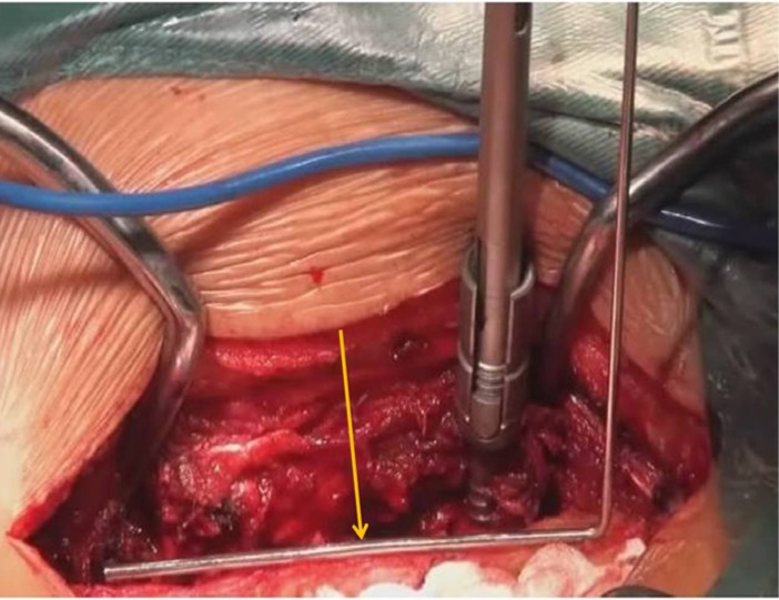
In the conventional technique group, we kept the screw parallel to the upper end plate by using a C-arm image system. At the same time, medial-lateral and cranial-caudal angles were adjusted under intraoperative fluoroscopy. The C-arm image system was frequently used to verify correct positioning of the trajectory of screws in the conventional technique group. In the new free-hand technique group, on the basis of the angle study above, the cranial-caudal angle was set at 90° making the trajectory of the screw perpendicular to the supraspinal ligament. The medial-lateral angle was set properly according to preoperative CT scans. Thoracic vertebrae and upper lumbar vertebrae screws were slightly oblique towards the midline (on an average about 5°-10°), and lower lumbar vertebrae screw was about 10° to 15° towards the midline the same as previous studies[2],[19]. During the operation, an “L” shaped self-designed measuring device (Fig. 4) was used to make the trajectory of the screw perpendicular to the supraspinal ligament. The position of pedicle screws and rods required confirmation only once at the end of the operation. Comparison of the main surgical procedures for inserting pedicle screws between the new method and conventional techniques are shown in supplementary figures (Supplementary Fig. 1A, 1B and 1C, available on line).
Fig. 4. “L” shaped measuring device (yellow arrow) is used during the operation which facilitates pedicle screw placement.
Pedicle screw placement was assessed on postoperative CT scan at 1 week by a single, independent, board-certified spine surgeon with more than 25 years of experience of spine surgery who was blinded to patient data and based on a postoperative CT scan obtained within 1 week after surgery. The magnitude of pedicle perforation was categorized as no breach, breach less than 2 mm, breach from 2 to 4 mm, breach from 4 to 6 mm and breach greater than 6 mm. The direction of perforation was categorized as lateral, medial, inferior or superior.
Statistical analysis
All continuous data were presented as mean± standard deviation (SD) and all categorical data as percentage or number. Statistical analyses for comparisons between groups were performed by using unpaired Student's t-test, χ2 test or non-parametric Kruskal-Wallis test. Statistical significance was set as P < 0.05. Statistical analysis was done using Stata version 10.1 (StataCorp, College Station, TX, USA).
RESULTS
In the new free-hand technique group, 77 patients with vertebral fractures at T1 to L4, (a total of 85 fractures including 8 fractures with two consecutive fractured vertebrae) received 322 pedicle screws (pedicle screws inserted in L5 were excluded) in the thoracic or lumbar spine. The number of screws inserted at each level is shown as follows: T1=2, T2=4, T3=2, T4=10, T5=10, T6=16, T7=12, T8=14, T9=18, T10=18, T11=32, T12=44, L1=42, L2=42, L3=36 and L4=20. Two screws (0.06%) were replaced due to their improper position, with no neurologic or vascular complications. Analysis of these pedicle screws by postoperative CT scans confirmed 10 (3.11%) violated screws, including 4 medial and 6 lateral pedicle cortical penetration but no superior and inferior penetrations. There was no neurologic, vascular or pleural injury and no screws required postoperative repositioning. The accuracy rate was 96.3% (12/322).
In the conventional technique group, 76 patients with vertebral fractures at T1 to L4 (a total of 82 fractures including 6 fractures with two consecutive fractured vertebrae) received 312 pedicle screws (pedicle screws inserted in L5 were excluded) placed in the thoracic or lumbar spine. The number of screws inserted at each level is shown as follows: T2=2, T3=6, T4=6, T5=12, T6=8, T7=18, T8=18, T9=20, T10=22, T11=26, T12=32, L1=36, L2=44, L3=38 and L4=24. Four screws (1.65%) were incorrectly positioned and replaced, and one of the pedicle breaches (1.28%) was associated with hypoesthesia. Postoperative CT scans showed 14 (4.49%) violated screws, including 4 medial, 3 lateral, 5 superior and 2 inferior pedicle cortical penetrations. The accuracy rate was 94.2% (18/312), which was significantly lower than the new free-hand technique group (P < 0.05).
There was also a statistically significant difference between the new and the conventional technique groups in fluoroscopy time (5.37 seconds vs. 8.79 seconds, P < 0.05). However, there was no statistically significant difference between the 2 groups in operating time and the volume of estimated blood loss during operation (P > 0.05) (Table 3 and 4).
Table 3. Surgical results.
| Total screws placed | New free hand group | Conventional group |
| Total screws placed | 322 | 312 |
| Screws per patient placed | 4.18 | 4.11 |
| Pedicle perforation | 12 | 18 |
| EMG monitoring | none | none |
| Neurological examination | none | none |
| Intraoperative complications | none | none |
Table 4. Comparison between new free hand group and conventional group on perforation parameters, distribution, fluoroscopy time, operative time, and estimated blood loss.
| Parameter | New free hand group | Conventionalgroup |
| Perforation | ||
| Replaced | 2 | 4 |
| Breach | ||
| No | 310 | 294 |
| < 2 mm | 8 | 8 |
| 2-4 mm | 2 | 5 |
| 4-6 mm | 0 | 1 |
| > 6 mm | 0 | 0 |
| Distribution | ||
| T1 | 0 | 0 |
| T2 | 1 | 0 |
| T3 | 0 | 2 |
| T4 | 2 | 0 |
| T5 | 0 | 3 |
| T6 | 4 | 2 |
| T7 | 2 | 3 |
| T8 | 1 | 2 |
| T9 | 0 | 0 |
| T10 | 1 | 3 |
| T11 | 0 | 1 |
| T12 | 1 | 1 |
| L1 | 0 | 0 |
| L2 | 0 | 1 |
| L3 | 0 | 0 |
| L4 | 0 | 0 |
| Fluoroscopy time (second) | 8.79±1.27* | 5.37±1.16* |
| Operative time (minute) | 103.40±15.74 | 92.04±18.53 |
| Estimated blood loss (mL) | 281.02±34.46 | 250.95±49.70 |
Note: Data are comparisons between the conventional techniques and the free-hand technique. *P < 0.05.
DISCUSSION
According to this study, the angle between the upper vertebral endplate and the surface of the supraspinal ligament from T1 to L4 was approximately 90°. Therefore, to design the new free-hand technique, we inserted the pedicle screw perpendicular to the surface of the supraspinal ligament and parallel to the surface of the upper endplate. Perhaps the most important attribute of any anatomical reference is that it facilitates safe and accurate screw placement. In this study, 96.3% of the screws in the new free-hand technique group were entirely intrapedicular and 99.4% had breach less than 2 mm, commonly considered to be within the “safe zone” around the pedicle[20],[21]. Kosmopoulos et al.[22] compared the accuracy of pedicle screw placement with and without the assistance of navigation for all spine levels in the general patient population and found that the median accuracy was 95.1% and 90.3%, respectively, which is similar to our results. Although many clinical studies reported a low incidence of neurological injury associated with misplaced screws, there was evidence that small cortical breaches can impact on the biomechanical strength of a construct[2],[11],[23],[24]. In this study, the accuracy rate was 96.3% in the new free-hand technique group without the assistance of navigation, and no sequelae were observed. The major advantage of the new free-hand technique is that it reduces the frequency of radiation exposure noticeably. It not only reduces radiation exposure, but also makes the operation much simpler. Furthermore, surgeons can utilize intraoperative anatomy to guide screw placement directly. As fluoroscopy remains an integral part of conventional pedicle screw placement, radiation exposure to the surgical team still remains a legitimate concern. Cumulative radiation dose can exceed regulatory occupational limits[25],[26]. With current CT and 3-dimensional fluoroscopy-based navigation systems, the patient is exposed to significant amounts of radiation during image acquisition even if the surgeon is able to step away[18],[27]. This study confirmed that the use of the “L” shaped measuring device significantly reduced fluoroscopy time. The angle between the upper vertebral endplate and the surface of the supraspinous ligament of L5 was about 80°, but the entry point of L5 for pedicle screw placement which we chose was different from previous studies; so we excluded L5 from this study.
However, as our study is a preliminary and a single-centered study, multi-center studies are required to further confirm our findings. Besides, this study was limited by focusing on simple fracture in the thoracic or lumbar spine, the small number of cases and the heterogeneity of the vertebral distribution. Furthermore, this new technique can only be employed in patients with intact spinous processes. The study may have been subjected to selection bias by the exclusion of patients with nerve or spinal cord injury, spinal deformity, serious spine transformation, or severe combined injury. Additionally, as the fractured vertebrae are mainly in the thoracolumbar spine, the results of the thoracic spine may have a great bias. In a follow-up study, we are currently examining pedicle screw placement by this method in other diseases of the spine, including spinal deformities.
To enhance the safety of pedicle screw fixation, the choice of correct anatomic landmark of the supraspinal ligament was sufficient. Pedicle screw placement with a new free-hand technique referring to the supraspinous ligament is an accurate, reliable and safe method to treat fracture of the spine.
Supplementary Figures
When the pedicle screw is inserted into the pedicle and vertebral body, it should be perpendicular to the surface of the supraspinous ligament. The pedicle screw (blue, line C) should be placed parallel to the surface of the upper vertebral end-plate (red, line A). However, the upper vertebral end-plate is not visible during surgery. So during the conventional free-hand method, the surgeon must make the pedicle clearly exposed or with the help of intraoperative fluoroscopy to guide pedicle screws at right orientation. Based on the angle between the upper vertebral end-plate and the surface of the supraspinous ligament from T1 to L4 is approximately 90°, we can just insert pedicle screws at the right angle with the supraspinous ligament (yellow, line B) making the screw being parallel to the surface of the upper vertebral end-plate.
A: The MR films of middle sagittal plane display the supraspinal ligament clearly behind the spinous process. B: The angle between the line which is parallel to the surface of the upper vertebral end-plate and the line of the connection between the upper and lower spinous process trailing edge was measured.
A: The main operational procedures for inserting the pedicle screws. (1) location of the goal vertebrae; (2) planting the pedicle screw into the right vertebrae; (3) fixing pedicle screws with rods and then reduction; (4) confirming the position of pedicle screws and rods. The differences between the new method and the conventional techniques are inserting the pedicle screws as described in step 2. The conventional techniques require four steps: ① To insert the guide pins into the corresponding vertebraes; ② To adjust the position and orientation of pedical screws by using guide pins; ③ To implant the pedicle screws with the help of the guide pins; ④ To locate the position and orientation of pedical screws by using guide pins. The conventional techniques are very complicated and not easy to manipulate. In addition, it increases the dangers of exposure to X-ray fluoroscopy. As for the new method, pedicle screws can be directly placed without using the guide pins. It is simple. More importantly, it reduces the hazards of X-ray fluoroscopy. B: To demonstrate the new method of specific surgical procedures. In the second step of the process of pedicle screw placement, without confirming its position, pedicle screws can be directly inserted into vertebraes, as referred to the Kirschner wire at a right angle shown in the figure. Most importantly, we only need to confirm the position of pedicle screws and rods once with a C-Arm image system. C: To demonstrate the conventional techniques of specific surgical procedures. In the second step of the process of pedicle screw placement, it requires inserting the guide pins and then a C-Arm image system is needed to verify the position and orientation of the guide pins. Next, pedicle screws are inserted and the C-Arm image system is needed to verify the position and orientation of pedicle screws. Finally, after fixing pedicle screws with rods, the C-Arm image system is still needed. Thus, roentgenogram is needed for 3 times during operation.
References
- 1.Gaines RW., Jr The use of pedicle-screw internal fixation for the operative treatment of spinal disorders. J Bone Joint Surg Am. 2000;82:1458–76. doi: 10.2106/00004623-200010000-00013. [DOI] [PubMed] [Google Scholar]
- 2.Kim YJ, Lenke LG, Bridwell KH, Cho YS, Riew KD. Free hand pedicle screw placement in the thoracic spine: is it safe? Spine. 2004;29:333–42. doi: 10.1097/01.brs.0000109983.12113.9b. [DOI] [PubMed] [Google Scholar]
- 3.Ebraheim NA, Jabaly G, Xu R, Yeasting RA. Anatomic relations of the thoracic pedicle to the adjacent neural structures. Spine. 1997;22:1553–1556. doi: 10.1097/00007632-199707150-00002. [DOI] [PubMed] [Google Scholar]
- 4.Ebraheim NA, Xu R, Darwich M, Yeasting RA. Anatomic relations between the lumbar pedicles and the adjacent neural structures. Spine. 1997;22:2338–41. doi: 10.1097/00007632-199710150-00003. [DOI] [PubMed] [Google Scholar]
- 5.Liljenqvist UR, Link TM, Halm HFH. Morphometric analysis of thoracic and lumbar vertebrae in idiopathic scoliosis. Spine. 2000;25:1247–53. doi: 10.1097/00007632-200005150-00008. [DOI] [PubMed] [Google Scholar]
- 6.O'Brien JR, Krushinski E, Zarro CM, Sciadini M, Gelb D, Ludwig S. Esophageal injury from thoracic pedicle screw placement in a polytrauma patient:a case report and literature review. J Orthop Trauma. 2006;20:431–4. doi: 10.1097/00005131-200607000-00012. [DOI] [PubMed] [Google Scholar]
- 7.Suk SI, Lee SM, Chung ER, Kim JH, Kim SS. Selective thoracic fusion with segmental pedicle screw fixation in the treatment of thoracic idiopathic scoliosis: more than 5-year follow-up. Spine. 2005;30:1602–9. doi: 10.1097/01.brs.0000169452.50705.61. [DOI] [PubMed] [Google Scholar]
- 8.Kim YJ, Lenke LG, Cheh G, Riew KD. Evaluation of pedicle screw placement in the deformed spine using intraoperative plain radiographs: a comparison with computerized tomography. Spine. 2005;30:2084–8. doi: 10.1097/01.brs.0000178818.92105.ec. [DOI] [PubMed] [Google Scholar]
- 9.Austin MS, Vaccaro AR, Brislin B, Nachwalter R, Hilibrand AS, Albert TJ. Image-guided spine surgery: a cadaver study comparing conventional open laminoforaminotomy and two image-guided techniques for pedicle screw placement in posterolateral fusion and nonfusion models. Spine. 2002;27:2503–8. doi: 10.1097/01.BRS.0000031274.34509.1E. [DOI] [PubMed] [Google Scholar]
- 10.von Jako RA, Carrino JA, Yonemura KS, Noda GA, Zhue W, Blaskiewicz D, et al. Electromagnetic navigation for percutaneous guide-wire insertion: accuracy and efficiency compared to conventional fl uoroscopic guidance. Neuroimage. 2009;47:T127–32. doi: 10.1016/j.neuroimage.2009.05.002. [DOI] [PubMed] [Google Scholar]
- 11.Kim CW, Lee YP, Taylor W, Oygar A, Kim WK. Use of navigation-assisted fluoroscopy to decrease radiation exposure during minimally invasive spine surgery. Spine J. 2008;8:584–90. doi: 10.1016/j.spinee.2006.12.012. [DOI] [PubMed] [Google Scholar]
- 12.Nakashima H, Sato K, Ando T, Inoh H, Nakamura H. Comparison of the percutaneous screw placement precision of isocentric C-arm 3-dimensional fluoroscopy-navigated pedicle screw implantation and conventional fluoroscopy method with minimally invasive surgery. J Spinal Disord Tech. 2009;22:468–72. doi: 10.1097/BSD.0b013e31819877c8. [DOI] [PubMed] [Google Scholar]
- 13.Lekovic GP, Potts EA, Karahalios DG, Hall G. A comparison of two techniques in image-guided thoracic pedicle screw placement: a retrospective study of 37 patients and 277 pedicle screws. J Neurosurg Spine. 2007;7:393–8. doi: 10.3171/SPI-07/10/393. [DOI] [PubMed] [Google Scholar]
- 14.Park P, Foley KT, Cowan JA, Marca FL. Minimally invasive pedicle screw fixation utilizing O-arm fl uoroscopy with computer-assisted navigation navigation: Feasibility, technique, and preliminary results. Surg Neurol Int. 2010;1:44. doi: 10.4103/2152-7806.68705. [DOI] [PMC free article] [PubMed] [Google Scholar]
- 15.Smith HE, Welsch MD, Sasso RC, Vaccaro AR. Comparison of radiation exposure in lumbar pedicle screw placement with fluoroscopy vs computer-assisted image guidance with intraoperative three-dimensional imaging. J Spinal Cord Med. 2008;31:532–7. doi: 10.1080/10790268.2008.11753648. [DOI] [PMC free article] [PubMed] [Google Scholar]
- 16.Tormenti MJ, Kostov DB, Gardner PA, Kanter AS, Spiro RM, Okonkwo DO. Intraoperative computed tomography image-guided navigation for posterior thoracolumbar spinal instrumentation in spinal deformity surgery. Neurosurg Focus. 2010;28:E11. doi: 10.3171/2010.1.FOCUS09275. [DOI] [PubMed] [Google Scholar]
- 17.Wood MJ, Mannion RJ. Improving accuracy and reducing radiation exposure in minimally invasive lumbar interbody fusion. J Neurosurg Spine. 2010;12:533–9. doi: 10.3171/2009.11.SPINE09270. [DOI] [PubMed] [Google Scholar]
- 18.Zausinger S, Scheder B, Uhl E, Heigl T, Morhard D, Tonn JC. Intraoperative computed tomography with integrated navigation system in spinal stabilizations. Spine. 2009;34:2919–26. doi: 10.1097/BRS.0b013e3181b77b19. [DOI] [PubMed] [Google Scholar]
- 19.Castro WH, Halm H, Jerosch J, Malms J, Steinbeck J, Blasius S. Accuracy of pedicle screw placement in lumbar vertebrae. Spine. 1996;21:1320–4. doi: 10.1097/00007632-199606010-00008. [DOI] [PubMed] [Google Scholar]
- 20.Gertzbein SD, Robbins SE. Accuracy of pedicular screw placement in vivo. Spine. 1990;15:11–4. doi: 10.1097/00007632-199001000-00004. [DOI] [PubMed] [Google Scholar]
- 21.Modi HN, Suh SW, Fernandez H, Yang JH, Song HR. Accuracy and safety of pedicle screw placement in neuromuscular scoliosis with free-hand technique. Eur Spine J. 2008;17:1686–96. doi: 10.1007/s00586-008-0795-6. [DOI] [PMC free article] [PubMed] [Google Scholar]
- 22.Kosmopoulos V, Schizas C. Pedicle screw placement accuracy. A meta-analysis. Spine. 2007;32:E111–20. doi: 10.1097/01.brs.0000254048.79024.8b. [DOI] [PubMed] [Google Scholar]
- 23.Idler C, Rolfe KW, Gorek JE. Accuracy of percutaneous lumbar pedicle screw placement using the oblique or “owl's-eye” view and novel guidance technology. J Neurosurg Spine. 2010;13:509–15. doi: 10.3171/2010.4.SPINE09580. [DOI] [PubMed] [Google Scholar]
- 24.Isaacs RE, Podichetty VK, Sandhu FA, Santiago P, Spears JD, Aaronson O, et al. Thoracic microendoscopic discectomy: a human cadaver study. Spine. 2005;30:1226–31. doi: 10.1097/01.brs.0000162275.95579.ee. [DOI] [PubMed] [Google Scholar]
- 25.Mroz TE, Abdullah KG, Steinmetz MP, Klineberg EO, Lieberman IH. Radiation exposure to the surgeon during percutaneous pedicle screw placement. J Spinal Disord Tech. 2011;24:264–7. doi: 10.1097/BSD.0b013e3181eed618. [DOI] [PubMed] [Google Scholar]
- 26.Rampersaud YR, Foley KT, Shen AC, Williams S, Solomito M. Radiation exposure to the spine surgeon during fluoroscopically assisted pedicle screw insertion. Spine. 2000;25:2637–45. doi: 10.1097/00007632-200010150-00016. [DOI] [PubMed] [Google Scholar]
- 27.Scheufler KM, Cyron D, Dohmen H, Eckardt A. Less invasive surgical correction of adult degenerative scoliosis. Part II: Complications and clinical outcome. Neurosurgery. 2010;67:1609–21. doi: 10.1227/NEU.0b013e3181f918cf. [DOI] [PubMed] [Google Scholar]
Associated Data
This section collects any data citations, data availability statements, or supplementary materials included in this article.
Supplementary Materials
When the pedicle screw is inserted into the pedicle and vertebral body, it should be perpendicular to the surface of the supraspinous ligament. The pedicle screw (blue, line C) should be placed parallel to the surface of the upper vertebral end-plate (red, line A). However, the upper vertebral end-plate is not visible during surgery. So during the conventional free-hand method, the surgeon must make the pedicle clearly exposed or with the help of intraoperative fluoroscopy to guide pedicle screws at right orientation. Based on the angle between the upper vertebral end-plate and the surface of the supraspinous ligament from T1 to L4 is approximately 90°, we can just insert pedicle screws at the right angle with the supraspinous ligament (yellow, line B) making the screw being parallel to the surface of the upper vertebral end-plate.
A: The MR films of middle sagittal plane display the supraspinal ligament clearly behind the spinous process. B: The angle between the line which is parallel to the surface of the upper vertebral end-plate and the line of the connection between the upper and lower spinous process trailing edge was measured.
A: The main operational procedures for inserting the pedicle screws. (1) location of the goal vertebrae; (2) planting the pedicle screw into the right vertebrae; (3) fixing pedicle screws with rods and then reduction; (4) confirming the position of pedicle screws and rods. The differences between the new method and the conventional techniques are inserting the pedicle screws as described in step 2. The conventional techniques require four steps: ① To insert the guide pins into the corresponding vertebraes; ② To adjust the position and orientation of pedical screws by using guide pins; ③ To implant the pedicle screws with the help of the guide pins; ④ To locate the position and orientation of pedical screws by using guide pins. The conventional techniques are very complicated and not easy to manipulate. In addition, it increases the dangers of exposure to X-ray fluoroscopy. As for the new method, pedicle screws can be directly placed without using the guide pins. It is simple. More importantly, it reduces the hazards of X-ray fluoroscopy. B: To demonstrate the new method of specific surgical procedures. In the second step of the process of pedicle screw placement, without confirming its position, pedicle screws can be directly inserted into vertebraes, as referred to the Kirschner wire at a right angle shown in the figure. Most importantly, we only need to confirm the position of pedicle screws and rods once with a C-Arm image system. C: To demonstrate the conventional techniques of specific surgical procedures. In the second step of the process of pedicle screw placement, it requires inserting the guide pins and then a C-Arm image system is needed to verify the position and orientation of the guide pins. Next, pedicle screws are inserted and the C-Arm image system is needed to verify the position and orientation of pedicle screws. Finally, after fixing pedicle screws with rods, the C-Arm image system is still needed. Thus, roentgenogram is needed for 3 times during operation.