

Abstract
Objectives
Understanding the relationship between the stimulus parameters of electroconvulsive therapy (ECT) and the electric field characteristics could guide studies on improving risk/benefit ratio. We aim to determine the effect of current amplitude and electrode size and spacing on the ECT electric field characteristics, compare ECT focality with magnetic seizure therapy (MST), and evaluate stimulus individualization by current amplitude adjustment.
Methods
ECT and double-cone-coil MST electric field was simulated in a 5-shell spherical human head model. A range of ECT electrode diameters (2–5 cm), spacing (1–25 cm), and current amplitudes (0–900 mA) were explored. The head model parameters were varied to examine the stimulus current adjustment required to compensate for interindividual anatomical differences.
Results
By reducing the electrode size, spacing, and current, the ECT electric field can be more focal and superficial without increasing scalp current density. By appropriately adjusting the electrode configuration and current, the ECT electric field characteristics can be made to approximate those of MST within 15%. Most electric field characteristics in ECT are more sensitive to head anatomy variation than in MST, especially for close electrode spacing. Nevertheless, ECT current amplitude adjustment of less than 70% can compensate for interindividual anatomical variability.
Conclusions
The strength and focality of ECT can be varied over a wide range by adjusting the electrode size, spacing, and current. If desirable, ECT can be made as focal as MST while using simpler stimulation equipment. Current amplitude individualization can compensate for interindividual anatomical variability.
Keywords: electroconvulsive therapy, magnetic seizure therapy, electric field, focality, model
Introduction
Electroconvulsive therapy (ECT) is the most effective treatment for severe depression due to its powerful and rapid therapeutic action in patients who are otherwise treatment resistant.1 However, ECT can cause amnesia and other side effects, which impedes its broader application.2,3 Various alterations of ECT technique have been introduced to achieve more focal stimulation, based on the theory that increased focality of the electrical stimulus and the resultant seizure may be a means of reducing adverse effects.4
Among the approaches that make ECT more focal, electrode placement has been the subject of most intensive investigation. The shift from bilateral (BL) to right unilateral (RUL) electrode placement is representative of the move toward more focal electrical stimulus delivery, based on the assumption that by reducing the spacing between the electrodes and placing them over the right hemisphere, the direct stimulation and seizure intensity in the left hemisphere can be reduced, thereby sparing verbal and memory functions. Indeed, with appropriately dosed electrical stimulus, RUL ECT can be as effective as BL ECT, while having fewer side effects.5 Bifrontal (BF) electrode placement6 is another approach to more targeted stimulation by focusing the electric field in the frontal cortex, which has been linked to the pathophysiology of depression and the antidepressant response of ECT.7–11 A number of studies have reported equivalent efficacy of BF ECT compared to BL and RUL ECT, with diminished impact on memory in some but not all studies.12–18 Both RUL and BF electrode placements have smaller inter-electrode spacing compared to BL electrode placement, which increases the focality of the induced electric field.19
Yet another strategy for eliciting focal seizures in the prefrontal cortex is focal electrically administered seizure therapy (FEAST),4,20,21 which is in an early stage of clinical evaluation and demonstrated significant antidepressant effects in an open label trial.22 FEAST uses a small anode (positive electrode) and a large cathode (negative electrode) with the aim to produce focal stimulation.4,20 This approach mirrors developments in subconvulsive transcranial electric stimulation where focality can be enhanced by using a small electrode over the target site paired with either a large-area return electrode or multiple return electrodes.23–35 In vivo studies of FEAST showed that this configuration has lower seizure threshold and induces more lateralized seizures compared to BL ECT.20,36 Our previous simulation results also demonstrated that the electric field induced by FEAST is intrinsically more focal compared to BL, RUL, and BF ECT.19
In addition to reducing the electrode spacing and size, decreasing the stimulus pulse width also increases the focality of stimulation by lowering the degree of neural membrane depolarization produced by each pulse.19 Consequently, shorter pulses can reduce the cognitive side effects of ECT while maintaining high therapeutic efficacy.4,37
Focal stimulation for deliberate seizure induction can also be achieved with high-dose repetitive transcranial magnetic stimulation (rTMS).38 It was thought that the intracerebral electric field induced by ECT is unfocal and variable due to the high electrical impedance of the skull, current shunting in the scalp, and variation of the head tissue anatomy within and between individuals.39 Magnetic seizure therapy (MST), in which seizures are induced using high-dose rTMS, was conceived as a means of increasing the focality and reducing the variability of the intracerebral electric field, since the scalp and skull do not distort the magnetic field.38,40,41 Indeed, we have shown that the MST electric field is 3–6 times weaker, 2–4 times more superficial, 10–60 times more focal, and less sensitive to anatomical variability compared to conventional ECT.19,42 A number of reports indicate that MST has antidepressant efficacy and has more benign cognitive side effects compared to conventional ECT.38,41,43–47 The only published head-to-head comparison between MST and ECT found comparable, significant antidepressant efficacy and no significant cognitive side effects in either treatment group.48 The ultimate efficacy of MST will need to be determined in a large trial with an adequately dosed form of ECT.
A disadvantage of MST is the relatively complex technology it requires compared to ECT. To induce suprathreshold electric fields in the brain, MST requires thousands of amperes of current delivered to the stimulation coil. The generation of such large currents with high pulse repetition rates necessitates stimulation devices that require high-power electric supply (e.g., 3-phase mains) and coil cooling equipment, are larger and more expensive than ECT devices, and have limited range of adjustment of the stimulus parameters (pulse amplitude, width, directionality, and train frequency and duration).4,49–52 The limited output range of MST technology poses a challenge to adequate dosing of focal seizure induction paradigms. Electric stimulation devices, on the other hand, are low power, compact, and flexible with practically no output limitations. Therefore, it is important to develop a better understanding of the ECT electric field characteristics, the capability to control their focality, their sensitivity to anatomical variation among patients, and how these compare to MST. Such insight could inform studies with either modality.
Despite mostly empirical developments toward making convulsive therapies more focal, the relations between ECT electrode geometry, size, positioning, and current amplitude and the induced electric field spatial distribution and strength have not been adequately characterized.53 The pulsed electric field and associated current density generated by ECT rhythmically depolarize neurons leading to hypersynchronized discharges of large neural groups that can result in a seizure.39,54 Since the electric field parameters affect the seizure expression55–58 and generalized seizures can be therapeutically effective or ineffective depending on the electric field parameters,5,37,59,60 understanding of the electric field characteristics associated with various ECT paradigms is important for studying the mechanisms of ECT and for optimizing its action.
A number of modeling studies have addressed the dependence of the induced electric field and current density on the electrode characteristics in various forms of transcranial electric stimulation. For fixed stimulus current, smaller electrodes produce a stronger and more focal electric field on the brain surface under the electrode.61,62 Increasing the inter-electrode distance reduces shunting of the current through the scalp and the cerebrospinal fluid.31,62 However, the effect of the stimulus current amplitude as well as a specific neural response threshold, which are key determinants of the focality of neural stimulation, was not examined in these studies. Furthermore, parameter ranges and quantification metrics relevant to ECT were not fully covered. Thus, adequate and practical characterization of the ECT electric field as a function of electrode configuration and current amplitude is lacking.
The effect of the stimulus current amplitude has also been overlooked in modern ECT and in MST studies, even though other techniques such as TMS and deep brain stimulation routinely incorporate stimulus amplitude adjustment as a means of controlling the stimulated brain volume.54 Conventional ECT uses a fixed current amplitude of 800 or 900 mA for all patients.54 Our previous simulation study suggests that at these current levels, the electric field strength in most of the brain exceeds significantly the threshold for robust neural activation.19 This observation is consistent with a case series of five patients in whom we successfully induced generalized seizures with 500 mA stimulus current,63 as well as with a review of older ECT studies that used low current amplitudes.54 Therefore, the electric field strength in conventional ECT may be higher than necessary for adequate seizure induction, potentially contributing to adverse side effects.
The induced electric field can be affected by interindividual variability in head anatomy, which could contribute to variability in clinical outcome among patients. The commonly used seizure threshold titration procedure for individualizing ECT dosage adjusts the duration and/or frequency of the stimulus pulse train, but not the pulse amplitude and rarely the pulse width.39,64 Thus, conventional titration procedures do not compensate for the anatomy-dependent variability in the strength and spatial extent of direct neural stimulation which is determined by the pulse amplitude and width. While the pulse width affects neural membrane depolarization in a non-linear fashion that may vary among different parts of the neuron, the pulse amplitude drives the membrane potential proportionally.54 Therefore, individualization of the ECT current amplitude could be a means of reducing clinical outcome variability.21,54,65,66 However, the degree of current amplitude adjustment required to compensate for interindividual anatomical variation has not been determined for either ECT or MST.
In this paper, we use a computational spherical head model to examine how ECT electrode shape, size, spacing, and current amplitude affect the electric field strength, focality, and depth. We indicate where conventional (BL, RUL, and BF) and experimental (FEAST) ECT paradigms fit on the continuum of stimulation parameters. A modality-specific neural activation threshold is incorporated into our model to determine the strength and focality of direct neural stimulation. We compare these results to a simulation of the electric field induced by MST and demonstrate that, if desirable, key characteristics of the electrically induced field can be matched to the magnetically induced field. Finally, we explore how the stimulus current amplitude should be adjusted to compensate for individual anatomical variability. This work was previously presented in part in a conference abstract.67
Materials and Methods
We simulated the electric field induced by ECT and MST in a spherical head model using the finite element method packages ElecNet and MagNet 7 (Infolytica Corp., Montreal, Canada), respectively. The modeling methods are described in detail by Deng et al.19,42 and are summarized below.
Head model
The human head was modeled as a three-dimensional sphere consisting of five shells: scalp, skull, cerebrospinal fluid, gray matter, and white matter, as shown in Figure 1(a). Despite the development of more anatomically accurate head models that reveal local detail of the electric field and current density distributions,68–70 the spherical model is a useful reduction for parametric studies of global electric field characteristics.19,31,34,71 The results obtained with the spherical model are not limited to a particular subject’s head anatomy, but rather are informative of the general effect of electrode size, spacing, and current.
Figure 1.
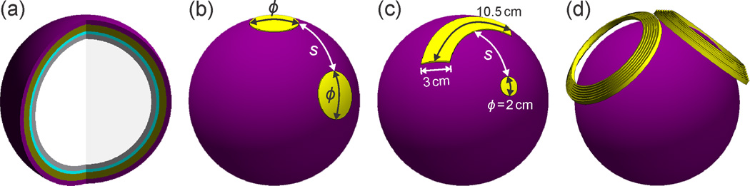
Simulation models of ECT electrode and MST coil configurations: (a) Interior of five-layer spherical head model. Tissue layers from outer to inner shell: scalp, skull, cerebrospinal fluid, gray matter, and white matter. (b) Symmetric disc electrode configuration with a range of edge-to-edge inter-electrode spacing (s = 1–25 cm) and electrode diameter (ϕ = 2, 3, and 5 cm). (c) Asymmetric electrode configuration consisting of a 2 cm diameter disc electrode and an arc-shaped electrode with 3 cm width, and 10.5 cm mid-arc length. (d) DCONE MST coil consisting of two adjacent concave windings fixed at a relative angle of 100°, each with an inner diameter of 9.6 cm, outer diameter of 12.5 cm, and 7 turns.
Since about 70% of ECT patients are women72 and since the results from spherical models with male and female parameters are comparable,42 in our nominal head model we used the average adult female head diameter, and scalp and skull thicknesses reported in morphometric studies and shown in Table 1.73–77 The tissue layers were assigned isotropic conductivities also given in Table 1.78–83 To represent the head anatomical variability, we perturbed the nominal model shells’ thickness and conductivity by introducing small changes to the nominal tissue parameters one at a time while holding the others parameters constant. We used the perturbed head models to explore how adjustment of the stimulus current amplitude can compensate for variations of the electric field strength and focality due to anatomical differences representative of the adult population.42
Table 1.
Nominal head model parameters
| Tissue | Thickness [mm] |
Conductivity [S−1] |
|---|---|---|
| Scalp | 5.60 | 0.3 |
| Skull | 7.08 | 0.0083 |
| Cerebrospinal fluid | 3.00 | 1.79 |
| Gray matter | 3.00 | 0.33 |
| White matter | 67.8 | 0.14 |
ECT electrode and MST coil configurations
For ECT, we simulated symmetric and asymmetric two-electrode configurations. The symmetric configurations consisted of two disc electrodes each with diameter ϕ and edge-to-edge inter-electrode spacing s [Figure 1(b)]. The electrode diameter ϕ was assigned values of 2, 3, or 5 cm, and s was assigned values ranging from 1 to 25 cm. The asymmetric electrode configuration models FEAST and consisted of a 2 cm diameter disc electrode and an arc-shaped electrode with 3 cm width, 10.5 cm mid-arc length, and area 10 times that of the smaller electrode [Figure 1(c)]. The edge-to-edge spacing between the large and small electrodes ranged from 1 to 24 cm. The electrodes were modeled as isopotential surfaces and the potential difference between the electrodes was adjusted to produce the desirable total electrode current. In clinical practice, electrolytic gel is applied to the ECT electrode surface to stabilize the electrode–scalp interface impedance. Since the electrolyte layer is very thin when the electrodes are pressed to the head, and since impedances in the FEM model are intrinsically stable, we did not model the gel layer.
For MST, double-cone (DCONE) coil (S/N MP40, Magstim Co., Whitland, Wales, UK) was modeled using manufacturer’s data and inductance measurements. The DCONE coil consisted of two adjacent windings fixed at a relative angle of 100°, each with an inner diameter of 9.6 cm, outer diameter of 12.5 cm, and 7 turns [Figure 1(d)]. The coil windings were modeled as solid copper wire with cross section of 6 mm × 1.75 mm. The coil conductors were placed at a minimum of 5 mm from the surface of the head model to account for the thickness of the insulating coil casing. The DCONE coil was used in our controlled trial of MST44,84 and has electric field characteristics similar to the MagVenture twin coil which was used in the MST study by Kayser et al.48
Electric field characterization
We quantified electric field penetration by the half-value depth, d1/2, defined as the radial distance from the cortical surface to the deepest point where the electric field strength E is half of its maximum value on the cortical surface, Emax.85 We quantified the intrinsic focality of each electrode or coil configuration by the half-value volume, V1/2, defined as the volume of the brain sphere (gray and white matter) that is exposed to electric field stronger than half of the maximum electric field.19,85 It is then expressed relative to the total brain volume, V1/2 / Vbrain. We also characterized the maximum electric field in the brain per unit of electrode current, Emax / Ielectrode. The above metrics depend only on the head anatomical parameters and the ECT electrode geometry and inter-electrode spacing or the MST coil geometry, and are independent of the pulse waveform parameters. Thus, these quanitites reflect purely the spatial targeting properties of the electrode/coil configuration.
For a fixed electrode or coil configuration, the stimulation strength and the directly stimulated brain volume are determined by the pulse waveform characteristics, such as pulse amplitude, shape, and width.86 The effect of pulse shape and width on the induced electric field has been discussed in previous modeling studies.19,54 In this study, we focused on the effect of current amplitude on the electric field strength and directly activated brain volume. The electric field strength is directly proportional to the ECT electrode current or the MST coil current.86 To assess the degree of direct neural stimulation, the electric field strength has to be compared to a neural activation threshold, Eth, that accounts for the pulse shape and width.19 The estimated electric field thresholds for robust neural activation are 0.35 V/cm for ultra-brief (0.3 ms pulse width) ECT and 1.0 V/cm for DCONE MST with 0.4 ms cosine pulses.19 We quantified the portion of the brain directly activated by ECT and MST by calculating the brain volume exposed to an electric field stronger than the neural activation threshold, VA, and expressing it relative to the total brain volume, VA / Vbrain.19
Finally, we evaluated the degree to which ECT and MST current amplitude adjustment compensates for head anatomical variability. The objective of amplitude adjustment would be to obtain comparable electric field characteristics in the brain for various subjects. The current can be individualized via current amplitude titration of seizure threshold54 or potentially via a motor threshold titration.65 The average size of the motor response to electric and magnetic stimulation is a monotonically increasing function of the induced electric field strength.87 Thus, the maximum electric field strength in the brain relative to threshold, Emax / Eth, would be comparable in different subjects if the stimulus current amplitude is individualized via motor threshold titration. Therefore, we modeled the effect of current individualization relative to motor threshold by adjusting the current in the anatomically perturbed head models to match Emax / Eth to that of the nominal model. The required current adjustment for this approach is denoted ΔIadj1. On the other hand, seizure initiation may require the recruitment of a neural population of a certain size.88,89 Consequently, current amplitude individualization by seizure threshold titration may yield comparable percent stimulated volume VA / Vbrain among different individuals. Therefore, we modeled the effect of current individualization relative to amplitude-titrated seizure threshold by adjusting the current in the anatomically perturbed head models so that VA /Vbrain matches that of the nominal model. The required current adjustment for this approach is denoted ΔIadj2.
Results
Figure 2 displays cross-sectional maps of the electric field strength relative to neural activation threshold for the symmetric and asymmetric electrode configurations at 2 cm and 15 cm inter-electrode spacing, as well as for DCONE MST. The simulation results for d1/2, V1/2 / Vbrain, and Emax / Ielectrode as a function of inter-electrode spacing are shown in Figure 3(a)–(c), respectively. Figure 3(d) shows the effect of current amplitude on the percent brain volume with electric field strength above the neural activation threshold, VA / Vbrain. Figure 4 plots the required stimulus current adjustment to compensate for head tissue thickness and conductivity variation for conventional BL and RUL ECT, for DCONE MST, and for a focal, MST-matched ECT configuration (ϕ = 3 cm, s = 2.2 cm).
Figure 2.

Cross-sectional profiles of the electric field strength (E) induced in the brain relative to neural activation threshold (Eth) for the symmetric and asymmetric ECT electrode configurations at 2 cm and 15 cm inter-electrode spacing (s), as well as for DCONE MST. The cross section is cut in the plane formed by the electrode and sphere centers or in the plane between the two windings of the DCONE coil. The total ECT current injected in the scalp is Ielectrode = 300 mA and the MST coil current Icoil corresponds to the maximum of a Magstim Theta MST device. The E / Eth color map is clamped at an upper limit of 2 for good visibility of the distribution of near-threshold electric field strengths.
Figure 3.
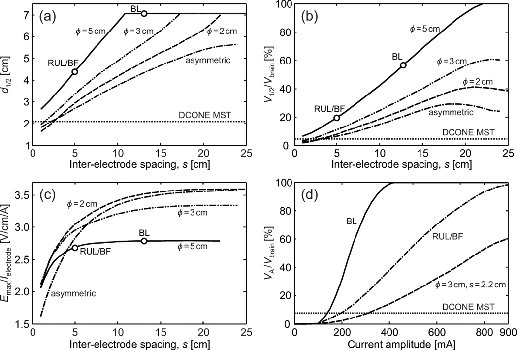
Effect of electrode configuration (symmetric or assymetric) and size (ϕ, for symmetric electrodes), inter-electrode spacing (s), and current amplitude on the electric field characteristics: (a) electric field half-value depth, d1/2, (b) percentage of brain volume that is exposed to electric field larger than half-maximum, V1/2 /Vbrain, and (c) maximum electric field induced per unit of electrode current, Emax / Ielectrode, as a function of inter-electrode spacing and (d) perecentage directly activated brain volume, VA / Vbrain, as a function of current amplitude for BL, RUL, and BF ECT, and MST-matched ECT (ϕ = 3 cm, s = 2.2 cm) configurations. For comparison, the values of d1/2, V1/2 / Vbrain, and VA / Vbrain for DCONE MST are indicated with a horizontal dotted line in (a), (b), and (d), respectively.
Figure 4.
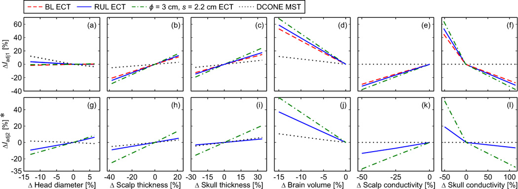
ECT and MST current amplitude adjustment to compensate for head tissue layer thickness and conductivity variations: (a)–(f) ΔIadj1 is the percentage change in the electrode or coil current amplitude required to match the maximum electric field in the brain to that of the nominal head model. (g)–(l) ΔIadj2 is the percentage change in the current amplitude required to match the directly activated brain volume, VA / Vbrain, to that of the nominal model. The horizontal axes reflect percentage change relative to the nominal model of head diameter, scalp thickness, skull thickness, brain volume, scalp conductivity, and skull conductivity. In the nominal model, the electrode current is 800 mA for BL and RUL ECT, and 300 mA for the MST-matched ECT (ϕ = 3 cm, s = 2.2 cm). The coil current is set to the maximum for the Magstim Theta MST device. (*) BL ECT at 800 mA yields VA / Vbrain = 100% for all anatomical parameters. Therefore, ΔIadj2 for BL ECT cannot be calculated meaningfully and is not plotted.
Effect of inter-electrode spacing
As shown in Figure 2 and 3(a), widening the inter-electrode spacing increases the depth of stimulation for all electrode shapes and sizes. DCONE MST has half-value depth of approximately 2 cm from the cortical surface. Figure 3(a) indicates that d1/2 of DCONE MST can be matched by the 2 cm, 3 cm, and asymmetric electrode configurations at an inter-electrode spacing of 1.5–2.5 cm, but cannot be matched by the conventional 5 cm ECT electrodes. Conventional BL ECT (5 cm electrode diameter and inter-electrode spacing of approximately 13 cm) has d1/2 equal to the radius of the brain (~ 7 cm). This means that for the BL electrode placement, the whole brain is exposed to electric field strength higher than the half-maximum.
Increasing the inter-electrode spacing also increases the brain volume with electric field above half-maximum, V1/2 / Vbrain, i.e., it reduces focality [Figure 3(b)]. DCONE MST has V1/2 / Vbrain = 4.5%, which can be matched by the 2 cm, 3 cm, and asymmetric electrode configurations at an inter-electrode spacing of 2–3 cm.
Finally, as the inter-electrode spacing increases, the induced maximum electric field per unit of electrode current, Emax / Ielectrode, increases for all electrode configurations [Figure 3(c)].
Effect of electrode geometry and size
For any fixed inter-electrode spacing, the values of both d1/2 and V1/2 / Vbrain increase with larger electrode diameter [Figure 3(a) and (b)]. On the other hand, Emax / Ielectrode decreases with larger electrode diameter [Figure 3(c)]. In the special case of the asymmetric electrode configuration, representative of FEAST, the values for both d1/2 and V1/2 / Vbrain are generally lower compared to the symmetric configurations, indicating a more superficial and focal electric field.
Effect of current amplitude
The induced electric field strength varies linearly with current amplitude. Thus, the current amplitude controls the electric field strength relative to the neural activation threshold and the directly stimulated brain volume. Consequently, the directly stimulated brain volume, VA / Vbrain, increases with higher current amplitude [Figure 3(d)]. At the conventional current of 800 mA, RUL/BF ECT and BL ECT stimulate 94% and 100% of the brain volume above threshold, respectively. Figure 3(d) also includes data for a configuration with electrode diamater ϕ = 3 cm and spacing s = 2.2 cm. This electrode configuration is of interest since it has electric field focality parameters similar to those of DCONE MST. Specifically, at current amplitude of 300 mA, this configuration has V1/2 / Vbrain, Emax / Eth, and VA / Vbrain that match those for DCONE MST within 5%, and d1/2 that matches that for MST within 15%. This similarity of the electric field focality is evident when comparing the ϕ = 3 cm, s = 2 cm, Ielectrode = 300 mA ECT electrode configuration with DCONE MST in Figure 2. Finally, the maximum scalp current density for the MST-matched ECT configuration (ϕ = 3 cm, s = 2.2 cm, Ielectrode = 300 mA) is 20% lower compared to that for conventional RUL ECT at 800 mA, indicating that despite the close electrode spacing needed to achieve focality similar to that of MST, the current shunting in the scalp is within safe levels.
Effect of amplitude individualization
Figure 4 shows two current amplitude adjustment paradigms for compensation of tissue layer thickness and conductivity variations. Variable ΔIadj1 is the change in the ECT electrode or MST coil current amplitude required to match Emax / Eth to that of the nominal model [see Figure 4 (a)–(f)]. Variable ΔIadj2 is the change in the current amplitude required to match VA / Vbrain to that of the nominal model [see Figure 4 (g)–(l)]. The horizontal axes give the percentage change of head diameter, scalp thickness, skull thickness, brain volume, scalp conductivity, and skull conductivity relative to the nominal model.
Compared to MST, the ECT electric field is more sensitive to head anatomical variability. This is illustrated by the greater change in the current amplitude, ΔIadj1 and ΔIadj2, required to compensate for variations in tissue layer thickness and conductivity (up to 68% for ECT and less than 12% for MST). The sole exception is the sensitivity of ΔIadj1 to head diameter changes which is greater for MST than for ECT [see Figure 4(a)]. The contribution of the head diameter variation to electric field variability, however, is relatively minor compared to that of the other anatomical parameters.
Within ECT, the MST-matched configuration requires the largest current amplitude adjustment to compensate for anatomical variations, as demonstrated by its steeper ΔIadj1 and ΔIadj2 slopes compared to BL and RUL ECT in Figure 4. The brain volume stimuated at suprathreshold level in BL ECT remains saturated at VA / Vbrain = 100% regardless of the anatomical variations. Therefore, ΔIadj2 for BL ECT cannot be calculated meaningfully and is not plotted in Figure 4.
Discussion
Role of electrode size, geometry, and inter-electrode spacing
Electrode size, geometry, and spacing have significant effect on the electric field distribution induced with ECT. As the inter-electrode spacing increases, the electric field becomes intrinsically more deeply penetrating and less focal [Figure 3(a),(b)], and its strength increases [Figure 3(c)] since less current is shunted in the scalp and more current enters the brain. These observations are consistent with previous simulation studies on transcranial electric stimulation.31,62
Smaller electrodes produce electric fields that are more superficial, more focal, and stronger per unit stimulation current than electrodes of larger diameter [Figure 3(a)–(c)]. This is consistent with the simulation results by Stecker and Faria et al. who showed that smaller electrodes produce more highly peaked distributions of current over a narrower angular area.61,62
The asymmetric electrode configuration is intrinsically more superficial and more focal than the symmetric configurations. However, this effect diminishes as the inter-electrode spacing is reduced since the current density around the larger electrode becomes more concentrated on the edge facing the smaller electrode, thus decreasing the effective size of the larger electrode. As the inter-electrode spacing increases, the smaller electrode in the asymmetric configuration dictates the maximum induced electric field strength. This can be seen in Figure 3(c), where Emax / Ielectrode for the asymmetric configuration approaches that for the ϕ = 2 cm configuration as s increases.
As evidenced by the slopes of the plots in Figure 3(a)–(c), compared to larger electrodes the electric field generated by smaller electrodes has intrinsic depth and focality, d1/2 and V1/2 / Vbrain, that are less sensitive to the inter-electrode spacing, but has strength, Emax / Ielectrode, that is more sensitive to the inter-electrode spacing. For all electrode sizes, the sensitivity of the electric field strength to the inter-electrode spacing is higher at smaller inter-electrode distances (e.g., compare the slopes of the curves in Figure 3(c) for s < 5 cm versus s > 5 cm). Lower sensitivity to inter-electrode spacing in advantageous since the electric field characteristics are less affected by variability in electrode placement. However, variations in the electric field strength due to errors in the electrode placement could be compensated partially by adjusting the electrode current via motor threshold or seizure threshold titration in the current amplitude domain (see also Role of current amplitude individualization section below).
Role of current amplitude
Current amplitude has a profound impact on focality. The linearity of the electric field solution with respect to the current amplitude implies that various stimulation strengths can be extrapolated from the simulation results. In present clinical ECT practice, a fixed pulse amplitude of 800 or 900 mA is delivered to all patients. At these current amplitudes, the majority of the neurons in the brain are stimulated above threshold for BL, RUL, and BF ECT [Figure 3(d)]. The maximum electric field in the brain exceeds the threshold for robust neural activation by more than six fold, potentially much higher than necessary for seizure induction.19 Substantially lower current amplitudes (233–650 mA) have been reported to trigger therapeutic seizures with low side effect profile.66,90–94 Our results are consistent with these studies, as Figure 3(d) indicates that the conventional electrode configurations with current greater than 233 mA stimulate larger portions of the brain compared to MST. MST can elicit generalized seizures84 despite producing stimulation strength 3–6 times weaker and focality 10–60 times higher than conventional ECT with 800 mA, 0.3 ms pulses.19 Altogether, these studies support the view that lowering the ECT pulse amplitude may still induce therapeutic seizures while potentially reducing cognitive disruptions.
Alternatively, the pulse width could be reduced further, below the currently used levels of 0.25–0.3 ms for ultrabrief ECT. Pulse width reduction will increase the threshold amplitude for neural activation. At present the difference in the effect of pulse width versus amplitude adjustment is not fully understood in the context of ECT, but it is known that both affect the degree of induced membrane depolarization.65
To preserve therapeutic efficacy, reduction of the current amplitude or pulse width may have to be accompanied by adjustment of other stimulus parameters such as the number and frequency of stimulus pulses.54 This hypothesis should be evaluated in clinical trials.
Role of current amplitude individualization
Our results support the use of current amplitude individualization as a means of compensating for interindividual variability in head anatomy. Figure 4 shows that it is always possible to adjust the current amplitude such that Emax / Eth and VA / Vbrain match those of the nominal model. The metrics Emax / Eth and VA / Vbrain are assumed to be related to the motor threshold and amplitude-titrated seizure threshold, respectively. In general, the percentage change in the current amplitude required to match Emax / Eth or VA / Vbrain to those of the nominal model is higher for ECT than for MST. These observations are consistent with our preliminary data on amplitude-titrated seizure threshold in nonhuman primates which showed a coefficient of variation of 0.37 in ECT but only 0.11 in MST.65 The sensitivity to anatomical variability is significant not only for inter-individual differences, but also for within-subject differences in the tissue layer tickness and conductivity in various parts of the head, as well as differences due to time-variant state of the tissues, such as the presence of perspiration in the scalp.
These results could be useful for determining whether current amplitude individualization is relevant to ECT and/or MST. For example, the largest current adjustment we computed was ~ 68% for ECT. Therefore, it is reasonable to expect that in reality individual variability would require more than ~ 10% current adjustment (making current individualization relevant) and less than ~ 100% (making current individualization practical). Thus, we can conclude that current amplitude individualization is relevant for ECT. On the other hand, MST requires less than 12% current adjustment, making current individualization in MST potentially less relevant.
Individualization of the current amplitude, which is not presently done in ECT or MST, could be a means of reducing clinical outcome variability. Individualization of stimulus dosage could be accomplished by titrating seizure threshold in the current amplitude domain, or by titrating motor threshold since amplitude-titrated seizure threshold and motor threshold are strongly correlated for both ECT and MST.65 Finally, setting the stimulus current amplitude relative to the motor threshold or seizure threshold could also compensate partially for small errors in the electrode or coil placement.
Range of ECT focality
We demonstrated the flexible range of control of the ECT electric field characteristics that is possible by manipulation of the electrode size, shape, spacing, and current amplitude. As a basis of comparison, we showed that ECT can achieve focality approaching that of MST, which is presently the most focal form of seizure induction. For example, using 3 cm diameter electrodes positioned 2.2 cm apart and current amplitude of 300 mA, the electric field distribution is similar to that of DCONE MST, as shown in Figure 2 and 3. Because of the lower current amplitude, the closer electrode spacing in this approach does not increase the scalp current density relative to conventional ECT. The ECT electric field is more sensitive to anatomical variations compared to MST (Figure 4), but this sensitivity can be compensated by individualization of the electrode current, as discussed above.
While the clinical value of ECT with a focal electric field such as the MST-matched ECT configuration is unknown, these results are methodologically important as they show that seizure induction with a focal electric field appears feasible with electric stimulation which requires simpler equipment than magnetic stimulation. Furthermore, our study establishes a technical comparison point between ECT and MST so that data from MST studies could inform ECT studies, and vice versa.
Limitations
As with any modeling study, the simulation data in this paper is subject to model limitations and should be used cautiously as an aid to interpret and inform experimental studies, and as a starting point for more detailed simulation studies. The spherical model significantly simplifies the head anatomy, thus the electric field solution is approximate.19 Nevertheless, the spherical model is useful for the purpose of identifying relationships among the stimulus parameters and the electric field characteristics that can subsequently be evaluated in more detail in realistic head models69,70 and in preclinical and clinical studies. We expect the general relationships between inter-electrode spacing, current amplitude, and electric field depth and focality to hold up in a realistic head model. Incorporating realistic cortical folding35,69,95 and white matter anisotropy70,96 in the model can increase the maximum local electric field strength up to 40–50%.35,69,70,95,96 The increased complexity and anatomical variability, and potentially increased electric field strength in realistic heads amplify our argument that lowering and individualizing the current strength in ECT could be beneficial. Furthermore, since the higher electric field strength in realistic head models is seen for both electric and magnetic stimulation,69,97–101 it is not expected to affect significantly the comparison between ECT and MST. Future work could use more anatomically accurate head models that include tissue anisotropy and could analyze the electric field in specific brain regions, as we have demonstrated in an ECT modeling study.70 Potential limitations of both spherical and anatomically realistic models include uncertainty about the various tissue conductivity values as well as errors in the tissue segmentation in realistic models or uncertainty in the assumptions of the shells’ thickness in the spherical model.
Near-threshold transcranial electric and magnetic stimulation are known to affect different neuronal populations in the cortex due to differences in electric field orientation.87,102,103 However, as the inter-electrode spacing decreases, the ECT induced electric field becomes more tangential,33,62 which gives a better approximation of the DCONE MST field distribution. In particular, for the MST-matched ECT configuration, the maximum electric field occurs midway between the electrodes (see Figure 2), where the field is completely tangential. Therefore, even though we did not compare explicitly the electric field direction between focal ECT and MST, presumably it can be matched approximately as well.
The electric field strength may not have a simple and direct relationship to the seizure initiation site, since various brain regions have different seizure thresholds.104,105 Furthermore, our model does not account for seizure propagation which is strongly affected by the anatomical and functional connectivity of the brain.106–109 Nevertheless, the local electric field strength is an important determinant of the likelihood of seizure initiation at that location as demonstrated by focal seizure induction with spatially targeted electric field.4,7,20,41 Furthermore, the electric field strength by itself may contribute to neuromodulatory effects that influence both therapeutic and side effects of ECT.54 Therefore, analyzing and controlling the induced electric field characteristics is an important step toward the refinement of convulsive therapies.
Conclusions
This simulation study addressed several issues of theoretical and practical importance for ECT technique. We systematically characterized the dependence of the electric field penetration, focality, and strength on various stimulus parameters such as electrode size, shape, spacing, and current amplitude. The maximum electric field strength increases if either the electrode size is decreased or the electrode spacing is increased. By reducing the electrode size or inter-electrode spacing, the ECT electric field becomes intrinsically more focal and superficial. Asymmetric electrode configurations can be explored as a means of further enhancing the focality of ECT. Lowering the current amplitude reduces the electric field strength and the directly activated brain volume. The latter relationship is described by a sigmoid curve with characteristics dependent on the electrode configuration parameters. Our simulation results are consistent with experimental findings that generalized seizures can be induced with currents significantly lower than the conventionally used 800 or 900 mA. For example, for ECT using 3 cm diameter electrodes positioned 2.2 cm apart and current amplitude of 300 mA, the depth and focality of stimulation and the electrical field strength relative to threshold are similar to those for DCONE MST. The electric field in ECT, however, is more sensitive to head anatomical variability than in MST. Nevertheless, current amplitude individualization can compensate for interindividual anatomical variability. Thus, transcranial stimulation for seizure induction with a wide range of intensity and focality appears feasible with electric stimulation which uses simpler equipment than magnetic stimulation. These findings may inform the redesign of ECT devices to provide a wider current amplitude range. While these simulation results cannot establish how the ECT stimulus parameters affect clinical outcome, they could inform experimental studies to optimize the stimulus to reduce side effects while retaining efficacy. Parameter optimization to improve seizure induction efficiency could also help address the clinical problem of patients with exceptionally high seizure threshold who cannot be adequately treated with existing devices.
Acknowledgments
We thank Dr. Andrew D. Krystal of Duke University for helpful discussions and comments on this manuscript.
Source of Funding
Dr. Deng is inventor on patent applications on TMS/MST technology assigned to Columbia. Dr. Lisanby has served as Principal Investigator on industry-sponsored research grants to Columbia/RFMH or Duke (Neuronetics (past), Brainsway, ANS/St. Jude Medical, Cyberonics (past), NeoSync); equipment loans to Columbia or Duke (Magstim, MagVenture); is co-inventor on a patent application on TMS/MST technology; is supported by grants from NIH (R01MH091083-01, 5U01MH084241-02, 5R01MH060884-09), Stanley Medical Research Institute, and Brain & Behavior Research Foundation / NARSAD; and has no consultancies, speakers bureau memberships, board affiliations, or equity holdings in related device industries. Dr. Peterchev is inventor on patents and patent applications on TMS/MST technology assigned to Columbia and Duke, including technology licensed to Rogue Research; was Principal Investigator on a research grant to Duke from Rogue Research and equipment donations to Columbia and Duke by Magstim, MagVenture, and ANS/St. Jude Medical; and has received patent royalties from Rogue Research through Columbia for TMS technology. Dr. Peterchev is supported by NIH grant R01MH091083 and Duke Institute for Brain Sciences Research Incubator Award. This work was supported in part by National Institutes of Health grants R01MH60884 and R01MH091083.
Footnotes
Publisher's Disclaimer: This is a PDF file of an unedited manuscript that has been accepted for publication. As a service to our customers we are providing this early version of the manuscript. The manuscript will undergo copyediting, typesetting, and review of the resulting proof before it is published in its final citable form. Please note that during the production process errors may be discovered which could affect the content, and all legal disclaimers that apply to the journal pertain.
Conflicts of Interest
Contributor Information
Zhi-De Deng, Email: zd2119@columbia.edu.
Sarah H. Lisanby, Email: sarah.lisanby@duke.edu.
Angel V. Peterchev, Email: angel.peterchev@duke.edu.
References
- 1.APA. The Practice of Electroconvulsive Therapy: Recommendations for Treatment, and Privileging: A Task Force Report of the American Psychiatric Association. Washington, DC: American Psychiatric Association; 2001. [Google Scholar]
- 2.Sackeim HA, Prudic J, Fuller R, Keilp J, Lavori PW, Olfson M. The cognitive effects of electroconvulsive therapy in community settings. Neuropsychopharmacology. 2007;32:244–254. doi: 10.1038/sj.npp.1301180. [DOI] [PubMed] [Google Scholar]
- 3.Nuttall GA, Bowersox MR, Douglass SB, McDonald J, Rasmussen LJ, Decker PA, et al. Morbidity and mortality in the use of electroconvulsive therapy. J ECT. 2004;20:237–241. doi: 10.1097/00124509-200412000-00009. [DOI] [PubMed] [Google Scholar]
- 4.Sackeim HA. Convulsant and anticonvulsant properties of electroconvulsive therapy: towards a focal form of brain stimulation. Clin Neurosci Res. 2004;4:39–57. [Google Scholar]
- 5.Sackeim HA, Prudic J, Devanand DP, Nobler MS, Lisanby SH, Peyser S, et al. A prospective, randomized, double-blind comparison of bilateral and right unilateral electroconvulsive therapy at different stimulus intensities. Arch Gen Psychiatry. 2000;57:425–434. doi: 10.1001/archpsyc.57.5.425. [DOI] [PubMed] [Google Scholar]
- 6.Abrams R, Taylor MA. Anterior bifrontal ECT: a clinical trial. Br J Psychiatry. 1973;122:587–590. doi: 10.1192/bjp.122.5.587. [DOI] [PubMed] [Google Scholar]
- 7.Nobler MS, Sackeim HA, Prohovnik I, Moeller JR, Mukherjee S, Schnur DB, et al. Regional cerebral blood flow in mood disorders, III. Treatment and clinical response. Arch Gen Psychiatry. 1994;51:884–897. doi: 10.1001/archpsyc.1994.03950110044007. [DOI] [PubMed] [Google Scholar]
- 8.Nobler MS, Oquendo MA, Kegeles LS, Malone KM, Campbell CC, Sackeim HA, et al. Decreased regional brain metabolism after ECT. Am J Psychiatry. 2001;158:305–308. doi: 10.1176/appi.ajp.158.2.305. [DOI] [PubMed] [Google Scholar]
- 9.Sackeim HA, Luber B, Katzman GP, Moeller JR, Prudic J, Devanand DP, et al. The effects of electroconvulsive therapy on quantitative electroencephalograms. Relationship to clinical outcome. Arch Gen Psychiatry. 1996;53:814–824. doi: 10.1001/archpsyc.1996.01830090060009. [DOI] [PubMed] [Google Scholar]
- 10.Soares JC, Mann JJ. The functional neuroanatomy of mood disorders. J Psychiatr Res. 1997;31:393–432. doi: 10.1016/s0022-3956(97)00016-2. [DOI] [PubMed] [Google Scholar]
- 11.Drevets WC. Functional neuroimaging studies of depression: the anatomy of melancholia. Annu Rev Med. 1998;49:341–361. doi: 10.1146/annurev.med.49.1.341. [DOI] [PubMed] [Google Scholar]
- 12.Bailine SH, Rifkin A, Kayne E, Selzer JA, Vital-Herne J, Blieka M, et al. Comparison of bifrontal and bitemporal ECT for major depression. Am J Psychiatry. 2000;157:121–123. doi: 10.1176/ajp.157.1.121. [DOI] [PubMed] [Google Scholar]
- 13.Bakewell CJ, Russo J, Tanner C, Avery DH, Neumaier JF. Comparison of clinical efficacy and side effects for bitemporal and bifrontal electrode placement in electroconvulsive therapy. J ECT. 2004;20:145–153. doi: 10.1097/00124509-200409000-00005. [DOI] [PubMed] [Google Scholar]
- 14.Little JD, Atkins MR, Munday J, Lyall G, Greene DCG, Orr M. Bifrontal electroconvulsive therapy in the elderly: a 2-year retrospective. J ECT. 2004;20:139–141. doi: 10.1097/00124509-200409000-00003. [DOI] [PubMed] [Google Scholar]
- 15.Delva NJ, Brunet D, Hawken ER, Kesteven RM, Lawson JS, Lywood DW, et al. Electrical dose and seizure threshold: relations to clinical outcome and cognitive effects in bifrontal, bitemporal, and right unilateral ECT. J ECT. 2000;16:361–369. doi: 10.1097/00124509-200012000-00006. [DOI] [PubMed] [Google Scholar]
- 16.Lawson JS, Inglis J, Delva NJ, Rodenburg M, Waldron JJ, Letemendia FJ. Electrode placement in ECT: cognitive effects. Psychol Med. 1990;20:335–344. doi: 10.1017/s0033291700017645. [DOI] [PubMed] [Google Scholar]
- 17.Letemendia FJ, Delva NJ, Rodenburg M, Lawson JS, Inglis J, Waldron JJ, et al. Therapeutic advantage of bifrontal electrode placement in ECT. Psychol Med. 1993;23:349–360. doi: 10.1017/s0033291700028452. [DOI] [PubMed] [Google Scholar]
- 18.Kellner CH, Knapp R, Husain MM, Rasmussen K, Sampson SCM, McClintock SM, et al. Bifrontal, bitemporal and right unilateral electrode placement in ECT: randomised trial. Br J Psychiatry. 2010;196:226–234. doi: 10.1192/bjp.bp.109.066183. [DOI] [PMC free article] [PubMed] [Google Scholar]
- 19.Deng Z-D, Lisanby SH, Peterchev AV. Electric field strength and focality in electroconvulsive therapy and magnetic seizure therapy: a finite element simulation study. J Neural Eng. 2011;8:016007. doi: 10.1088/1741-2560/8/1/016007. [DOI] [PMC free article] [PubMed] [Google Scholar]
- 20.Spellman T, Peterchev AV, Lisanby SH. Focal electrically administered seizure therapy: a novel form of ECT illustrates the roles of current directionality, polarity, and electrode configuration in seziure induction. Neuropsychopharmacology. 2009;34:2002–2010. doi: 10.1038/npp.2009.12. Erratum in Neuropsychopharmacology 2012 Mar; 37(4):1077. [DOI] [PMC free article] [PubMed] [Google Scholar]
- 21.Sackeim HA inventor. MECTA Corporation, assignee. Apparatus and method for focal electrically administered seizure therapy using titration in the current domain. 2010/0292750 A1. USPTO, US. 2010 Nov 18;
- 22.Nahas Z, Short B, Burns C, Archer M, Schmidt M, Prudic J, et al. A feasibility study of a new method for electrically producing seizures in man: focal electrically administered seizure therapy [FEAST] Brain Stimul. 2013;6:403–408. doi: 10.1016/j.brs.2013.03.004. [DOI] [PubMed] [Google Scholar]
- 23.Maccabee PJ, Amassian VE, Eberle LP, Cracco RQ. Magnetic coil stimulation of straight and bent amphibian and mammalian peripheral nerve in vitro: locus of excitation. J Physiol. 1993;460:201–219. doi: 10.1113/jphysiol.1993.sp019467. [DOI] [PMC free article] [PubMed] [Google Scholar]
- 24.Cracco RQ, Amassian VE, Maccabee PJ, Cracco JB. Comparison of human transcallosal responses evoked by magnetic coil and electrical stimulation. Electroencephalogr Clin Neurophysiol. 1989;74:417–424. doi: 10.1016/0168-5597(89)90030-0. [DOI] [PubMed] [Google Scholar]
- 25.Amassian VE, Cracco RQ, Maccabee PJ. Focal stimulation of human cerebral cortex with the magnetic coil: a comparison with electrical stimulation. Electroencephalogr Clin Neurophysiol. 1989;74:401–416. doi: 10.1016/0168-5597(89)90029-4. [DOI] [PubMed] [Google Scholar]
- 26.Nitsche MA, Doemkes S, Karakose T, Antal A, Liebetanz D, Lang N, et al. Shaping the effects of transcranial direct current stimulation of the human motor cortex. J Neurophysiol. 2007;97:3109–3117. doi: 10.1152/jn.01312.2006. [DOI] [PubMed] [Google Scholar]
- 27.Kwon YH, Ko MH, Ahn SH, Kim YH, Song JC, Lee CH, et al. Primary motor cortex activation by transcranial direct current stimulation in the human brain. Neurosci Lett. 2008;435:56–59. doi: 10.1016/j.neulet.2008.02.012. [DOI] [PubMed] [Google Scholar]
- 28.Phillips CG, Porter R. Unifocal and bifocal stimulation of the motor cortex. J Physiol. 1962;162:532–538. doi: 10.1113/jphysiol.1962.sp006948. [DOI] [PMC free article] [PubMed] [Google Scholar]
- 29.Rossini PM, Di Stefano E, Stanzione P. Nerve impulse propagation along central and peripheral fast conducting motor and sensory pathways in man. Electroencephalogr Clin Neurophysiol. 1985;60:320–334. doi: 10.1016/0013-4694(85)90006-9. [DOI] [PubMed] [Google Scholar]
- 30.Rossini PM, Marciani MG, Caramia M, Roma V, Zarola F. Nervous propagation along ‘central’ motor pathways in intact man: Characteristics of motor responses to ‘bifocal’ and ‘unifocal’ spine and scalp non-invasive stimulation. Electroencephalogr Clin Neurophysiol. 1985;61:272–286. doi: 10.1016/0013-4694(85)91094-6. [DOI] [PubMed] [Google Scholar]
- 31.Grandori F, Rossini P. Electrical stimulation of the motor cortex: theoretical considerations. Ann Biomed Eng. 1988;16:639–652. doi: 10.1007/BF02368019. [DOI] [PubMed] [Google Scholar]
- 32.Besio WG, Koka K, Cole AJ. Effects of noninvasive transcutaneous electrical stimulation via concentric ring electrodes on pilocarpine-induced status epilepticus in rats. Epilepsia. 2007;38:2273–2279. doi: 10.1111/j.1528-1167.2007.01202.x. [DOI] [PubMed] [Google Scholar]
- 33.Datta A, Elwassif M, Battaglia F, Bikson M. Transcranial current stimulation focality using disc and ring electrode configurations: FEM analysis. J Neural Eng. 2008;5:163–174. doi: 10.1088/1741-2560/5/2/007. [DOI] [PubMed] [Google Scholar]
- 34.Saypol JM, Roth BJ, Cohen LG, Hallett M. A theoretical comparison of electric and magnetic stimulation of the brain. Ann Biomed Eng. 1991;19:317–328. doi: 10.1007/BF02584306. [DOI] [PubMed] [Google Scholar]
- 35.Datta A, Bansal V, Diaz J, Patel J, Reato D, Bikson M. Gyri-precise head model of transcranial direct current stimulation: improved spatial focality using a ring electrode versus conventional rectangular pad. Brain Stimul. 2009;2:201–207. doi: 10.1016/j.brs.2009.03.005. [DOI] [PMC free article] [PubMed] [Google Scholar]
- 36.Berman RM, Sackeim HA, Truesdale MD, Luber B, Schroeder C, Lisanby SH. Focal electrically-administered seizure therapy (FEAST): nonhuman primate studies of a novel form of focal brain stimulation. J ECT. 2005;21:57. [Google Scholar]
- 37.Sackeim HA, Prudic J, Nobler MS, Fitzsimons L, Lisanby SH, Payne N, et al. Effects of pulse width and electrode placement on the efficacy and cognitive effects of electroconvulsive therapy. Brain Stimul. 2008;1:71–83. doi: 10.1016/j.brs.2008.03.001. [DOI] [PMC free article] [PubMed] [Google Scholar]
- 38.Lisanby SH, Schlaepfer TE, Fisch HU, Sackeim HA. Magnetic seizure therapy of major depression. Arch Gen Psychiatry. 2001;58:303–305. doi: 10.1001/archpsyc.58.3.303. [DOI] [PubMed] [Google Scholar]
- 39.Sackeim HA, Long J, Luber B, Moeller JR, Prohovnik I, Devanand DP, et al. Physical properties and quantification of the ECT stimulus: I. Basic principles. Convuls Ther. 1994;10:93–123. [PubMed] [Google Scholar]
- 40.Sackeim HA. Magnetic stimulation therapy and ECT. Convuls Ther. 1994;10:255–258. [PubMed] [Google Scholar]
- 41.Lisanby SH, Moscrip TD, Morales O, Luber B, Schroeder C, Sackeim HA. Neurophysiological characterization of magnetic seizure therapy (MST) in non-human primates. Clin Neurophysiol Suppl. 2003;56:81–99. doi: 10.1016/s1567-424x(09)70212-0. [DOI] [PubMed] [Google Scholar]
- 42.Deng Z-D, Lisanby SH, Peterchev AV. Effect of anatomical variability on neural stimulation strength and focality in electroconvulsive therapy (ECT) and magnetic seizure therapy (MST) Conf Proc IEEE Eng Med Biol Soc. 2009:682–688. doi: 10.1109/IEMBS.2009.5334091. [DOI] [PubMed] [Google Scholar]
- 43.Kayser S, Bewernick B, Axmacher N, Schlaepfer TE. Magnetic seizure therapy of treatment-resistant depression in a patient with bipolar disorder. J ECT. 2009;25:137–140. doi: 10.1097/YCT.0b013e31817dc45a. [DOI] [PubMed] [Google Scholar]
- 44.White PF, Amos Q, Zhang Y, Stool L, Husain MM, Thornton L, et al. Anesthetic considerations for magnetic seizure therapy: a novel therapy for severe depression. Anesth Analg. 2006;103:76–80. doi: 10.1213/01.ane.0000221182.71648.a3. [DOI] [PubMed] [Google Scholar]
- 45.Lisanby SH, Luber B, Schlaepfer TE, Sackeim HA. Safety and feasibility of magnetic seizure therapy (MST) in major depression: randomized within-subject comparison with electroconvulsive therapy. Neuropsychopharmacology. 2003;28:1852–1865. doi: 10.1038/sj.npp.1300229. [DOI] [PubMed] [Google Scholar]
- 46.Kosel M, Frick C, Lisanby SH, Fisch HU, Schlaepfer TE. Magnetic seizure therapy improves mood in refractory major depression. Neuropsychopharmacology. 2003;28:2045–2048. doi: 10.1038/sj.npp.1300293. [DOI] [PubMed] [Google Scholar]
- 47.Fitzgerald PB, Hoy KE, Herring SE, Clinton AM, Downey G, Daskalakis ZJ. Pilot study of the clinical and cognitive effects of high-frequency magnetic seizure therapy in major depressive disorder. Depress Anxiety. 2013;30:129–136. doi: 10.1002/da.22005. [DOI] [PubMed] [Google Scholar]
- 48.Kayser SB BH, Grubert C, Hadrysiewicz BL, Axmacher N, Schlaepfer TE. Antidepressant effects, of magnetic seizure therapy and electroconvulsive therapy, in treatment-resistant depression. J Psychiatr Res. 2011;45:569–576. doi: 10.1016/j.jpsychires.2010.09.008. [DOI] [PubMed] [Google Scholar]
- 49.Rowny SB, Benzl K, Lisanby SH. Translational development strategy for magnetic seizure therapy. Exp Neurol. 2009;219:27–35. doi: 10.1016/j.expneurol.2009.03.029. [DOI] [PMC free article] [PubMed] [Google Scholar]
- 50.Lisanby SH, Peterchev AV. Magnetic Seizure Therapy for the Treatment of Depression. In: Marcolin MA, Padberg F, editors. Transcranial Brain Stimulation for Treatment in Mental Disorders. New York: Karger Publishers; 2007. pp. 155–171. [Google Scholar]
- 51.Morales OG, Sackeim HA, Berman RM, Lisanby SH. Magnetic seizure therapy: development of a novel intervention for treatment resistant depression. Clin Neurosci Res. 2004;4:59–70. [Google Scholar]
- 52.Zyss T, Zieba A, Hese RT, Dudek D, Grabski B, Gorczyca P, et al. Magnetic seizure therapy (MST)--a safer method for evoking seizure activity than current therapy with a confirmed antidepressant efficacy. Neuro Endocrinol Lett. 2010;31:425–437. [PubMed] [Google Scholar]
- 53.Lerer B, Isserles M. From Meduna to ultrabrief: new directions for the oldest brain stimulation therapy. Brain Stimul. 2008;1:84–85. doi: 10.1016/j.brs.2008.03.005. [DOI] [PubMed] [Google Scholar]
- 54.Peterchev AV, Rosa MA, Deng Z-D, Prudic J, Lisanby SH. Electroconvulsive therapy stimulus parameters: rethinking dosage. J ECT. 2010;26:159–174. doi: 10.1097/YCT.0b013e3181e48165. [DOI] [PMC free article] [PubMed] [Google Scholar]
- 55.Krystal AD, Weiner RD, Mccall WV, Shelp FE, Arias R, Smith P. The effects of ECT stimulus dose and electrode placement on the ictal electroencephalogram: an intraindividual crossover study. Biol Psychiatry. 1993;34:759–767. doi: 10.1016/0006-3223(93)90064-k. [DOI] [PubMed] [Google Scholar]
- 56.Krystal AD, Weiner RD, Gassert D, McCall WV, Coffey CE, Sibert T, et al. The relative ability of three ictal EEG frequency bands to differentiate ECT seizures on the basis of electrode placement, stimulus intensity, and therapeutic response. Convuls Ther. 1996;12:13–24. [PubMed] [Google Scholar]
- 57.Nobler MS, Sackeim HA, Solomou M, Luber B, Devanand DP, Prudic J. EEG manifestations during ECT: effects of electrode placement and stimulus intensity. Biol Psychiatry. 1993;34:321–330. doi: 10.1016/0006-3223(93)90089-v. [DOI] [PubMed] [Google Scholar]
- 58.Cycowicz YM, Luber B, Spellman T, Lisanby SH. Neurophysiological characterization of high-dose magnetic seizure therapy: comparisons with electroconvulsive shock and cognitive outcomes. J ECT. 2009;25:157–164. doi: 10.1097/YCT.0b013e31818dd40a. [DOI] [PubMed] [Google Scholar]
- 59.Sackeim HA, Decina P, Kanzler M, Kerr B, Malitz S. Effects of electrode placement on the efficacy of titrated, low-dose ECT. Am J Psychiatry. 1987;144:1449–1455. doi: 10.1176/ajp.144.11.1449. [DOI] [PubMed] [Google Scholar]
- 60.Sackeim HA, Prudic J, Devanand DP, Kiersky JE, Fitzsimons L, Moody BJ, et al. Effects of stimulus intensity and electrode placement on the efficacy and cognitive effects of electroconvulsive therapy. N Engl J Med. 1993;328:839–846. doi: 10.1056/NEJM199303253281204. [DOI] [PubMed] [Google Scholar]
- 61.Stecker MM. Transcranial electric stimulation of motor pathways: a theoretical analysis. Comput Biol Med. 2005;35:133–155. doi: 10.1016/j.compbiomed.2003.12.005. [DOI] [PubMed] [Google Scholar]
- 62.Faria P, Hallett M, Miranda PC. A finite element analysis of the effect of electrode area and inter-electrode distance on the spatial distribution of the current density in tDCS. J Neural Eng. 2011;8:066017. doi: 10.1088/1741-2560/8/6/066017. [DOI] [PMC free article] [PubMed] [Google Scholar]
- 63.Rosa MA, Abdo G, Lisanby SH, Peterchev AV. Seizure induction with low-amplitude-current electroconvulsive therapy: a case series. J ECT. 2011;27:179. doi: 10.1097/YCT.0b013e31822149db. [DOI] [PubMed] [Google Scholar]
- 64.Sackeim HA, Decina P, Prohvnik I, Malitz S. Seizure threshold in electroconvulsive therapy: effects of sex, age, electrode placement, and number of treatments. Arch Gen Psychiatry. 1987;44:355–360. doi: 10.1001/archpsyc.1987.01800160067009. [DOI] [PubMed] [Google Scholar]
- 65.Peterchev AV, Chan B, Lisanby SH. Pulse amplitude adjustment: a novel means of individualizing and predicting dosage requirements for electroconvulsive therapy and magnetic seizure therapy. 20th Annual Meeting of the International Society for Neurostimulation; J ECT; 2010. pp. 154–155. [Google Scholar]
- 66.Liberson WT. Brief stimulus therapy - physiological and clinical observations. Am J Psychiatry. 1948;105:28–39. doi: 10.1176/ajp.105.1.28. [DOI] [PubMed] [Google Scholar]
- 67.Deng Z-D, Lisanby SH, Peterchev AV. Improving the focality of electroconvulsive therapy: the roles of current amplitude, and electrode size and spacing. 20th Annual Meeting of the International Society for Neurostimulation; New Orleans, LO. J ECT; 2010. p. 151. [Google Scholar]
- 68.Nadeem M, Thorlin T, Gandhi OP, Persson MA. Computation of electric and magnetic stimulation in human head using the 3-D impedance method. IEEE Trans Biomed Eng. 2003;50:900–907. doi: 10.1109/TBME.2003.813548. [DOI] [PubMed] [Google Scholar]
- 69.Thielscher A, Opitz A, Windhoff M. Impact of the gyral geometry on the electric field induced by transcranial magnetic stimulation. NeuroImage. 2011;54:234–243. doi: 10.1016/j.neuroimage.2010.07.061. [DOI] [PubMed] [Google Scholar]
- 70.Lee WH, Deng Z-D, Kim T-S, Laine AF, Lisanby SH, Peterchev AV. Regional electric field induced by electroconvulsive therapy in a realistic finite element head model: influence of white matter anisotropic conductivity. NeuroImage. 2012;59:2110–2123. doi: 10.1016/j.neuroimage.2011.10.029. [DOI] [PMC free article] [PubMed] [Google Scholar]
- 71.Grandori F, Ravazzani P. Magnetic stimulation of the motor cortex--theoretical considerations. IEEE Trans Biomed Eng. 1991;38:180–191. doi: 10.1109/10.76385. [DOI] [PubMed] [Google Scholar]
- 72.Rudorfer MV, Henry ME, Sackeim HA. Electroconvulsive therapy. In: Tasman A, Kay J, Lieberman JA, editors. Psychiatry. 2 ed. Chichester: John Wiley & Sons Ltd; 2003. pp. 1865–1901. [Google Scholar]
- 73.Örmeei AR, Gürbüz H, Ayata A, çetin H. Adult head circumferences and centiles. J Turgut Özal Med Cent. 1997;4:261–264. [Google Scholar]
- 74.Manjunath KY. Estimation of cranial volume in dissecting room cadavers. J Anat Soc India. 2002;51:168–172. [Google Scholar]
- 75.Hori H, Moretti G, Rebora A, Crovato F. The thickness of human scalp: normal and bald. J Invest Dermatol. 1972;58:396–399. doi: 10.1111/1523-1747.ep12540633. [DOI] [PubMed] [Google Scholar]
- 76.Lupin AJ, Gardiner RJ. Scalp thickness in the temporal region: its relevance to the development of cochlear implants. Cochlear Implants Int. 2001;2:30–38. doi: 10.1179/cim.2001.2.1.30. [DOI] [PubMed] [Google Scholar]
- 77.Li H, Ruan J, Xie Z, Wang H, Liu W. Investigation of the critical geometric characteristics of living human skulls utilising medical image analysis techniques. Int J Vehicle Safety. 2007;2:345–367. [Google Scholar]
- 78.Baumann SB, Wozny DR, Kelly SK, Meno FM. The electrical conductivity of human cerebrospinal fluid at body temperature. IEEE Trans Biomed Eng. 1997;44:220–223. doi: 10.1109/10.554770. [DOI] [PubMed] [Google Scholar]
- 79.Gabriel S, Lau RW, Gabriel C. The dielectric properties of biological tissues: II. Measurements in the frequency range 10 Hz to 20 GHz. Phys Med Biol. 1996;41:2251–2269. doi: 10.1088/0031-9155/41/11/002. [DOI] [PubMed] [Google Scholar]
- 80.Geddes LA, Baker LE. The specific resistance of biological material--a compendium of data for the biomedical engineer and physiologist. Med Biol Eng Comput. 1967;5:271–293. doi: 10.1007/BF02474537. [DOI] [PubMed] [Google Scholar]
- 81.Rush S, Driscoll DA. Current distribution in the brain from surface electrodes. Anesth Analg. 1968;47:717–723. [PubMed] [Google Scholar]
- 82.Wagner TA, Zahn M, Grodzinsky AJ, Pascual-Leone A. Three-dimensional head model simulation of transcranial magnetic stimulation. IEEE Trans Biomed Eng. 2004;51:1586–1598. doi: 10.1109/TBME.2004.827925. [DOI] [PubMed] [Google Scholar]
- 83.Wolters CH, Anwander A, Tricoche X, Weinstein D, Koch MA, MacLeod RS. Influence of tissue conductivity anisotropy on EEG/MEG field and return current computation in a realistic head model: a simulation and visualization study using high-resolution finite element modeling. NeuroImage. 2006;30:813–826. doi: 10.1016/j.neuroimage.2005.10.014. [DOI] [PubMed] [Google Scholar]
- 84.Lisanby SH, Husain MM, Morales OG, Thornton WL, White PF, Payne N, et al. Controlled clinical trial of the antidepressant efficacy of magnetic seizure therapy in the treatment of major depression. Am Coll Neuropsychopharmacol Ann Mtg. 2003:166. [Google Scholar]
- 85.Deng Z-D, Lisanby SH, Peterchev AV. Electric field depth–focality tradeoff in transcranial magnetic stimulation: simulation comparison of 50 coil designs. Brain Stimul. 2013;6:1–13. doi: 10.1016/j.brs.2012.02.005. [DOI] [PMC free article] [PubMed] [Google Scholar]
- 86.Peterchev AV, Wagner TA, Miranda PC, Nitsche MA, Paulus W, Lisanby SH, et al. Fundamentals of transcranial electric and magnetic stimulation dose: definition, selection, and reporting practices. Brain Stimul. 2012;5:435–453. doi: 10.1016/j.brs.2011.10.001. [DOI] [PMC free article] [PubMed] [Google Scholar]
- 87.Day BL, Dressler D, Maertens de Noordhout A, Marsden CD, Nakashima K, Rothwell JC, et al. Electric and magnetic stimulation of human motor cortex: surface EMG and single motor unit responses. J Physiol. 1989;412:449–473. doi: 10.1113/jphysiol.1989.sp017626. [DOI] [PMC free article] [PubMed] [Google Scholar]
- 88.Jefferys JG. Models and mechanisms of experimental epilepsies. Epilepsia. 2003;44:44–50. doi: 10.1111/j.0013-9580.2003.12004.x. [DOI] [PubMed] [Google Scholar]
- 89.Bikson M, Fox JE, Jefferys JG. Neuronal aggregate formation underlies spatiotemporal dynamics of nonsynaptic seizure initiation. J Neurophysiol. 2003;89:2330–2333. doi: 10.1152/jn.00764.2002. [DOI] [PubMed] [Google Scholar]
- 90.Gordon D. Electroconvulsive therapy. J Biomed Eng. 1989;11:170–171. doi: 10.1016/0141-5425(89)90131-3. [DOI] [PubMed] [Google Scholar]
- 91.Gordon D. Electro-convulsive therapy with minimum hazard. Br J Psychiatry. 1982;141:12–18. doi: 10.1192/bjp.141.1.12. [DOI] [PubMed] [Google Scholar]
- 92.Zyss T, Zięba A, Krawczyk A. Electricity of electroconvulsive therapy. J Tech Phys. 2002;43:543–561. [Google Scholar]
- 93.Hilkevitch A. Frequency and length of stimulus in electric shock therapy. AMA Arch Neurol Psychiatry. 1951;65:245–245. [Google Scholar]
- 94.Rosa MA, Abdo GL, Rosa MO, Lisanby SH, Peterchev AV. Fronto-medial electrode placement with low current amplitude: a case report. J ECT. 2012;28:146. [Google Scholar]
- 95.Manola L, Holsheimer J, Veltink P, Buitenweg JR. Anodal vs cathodal stimulation of motor cortex: a modeling study. Clin Neurophysiol. 2007;118:464–474. doi: 10.1016/j.clinph.2006.09.012. [DOI] [PubMed] [Google Scholar]
- 96.Opitz A, Windhoff M, Heidemann RM, Turner R, Thielscher A. How the brain tissue shapes the electric field induced by transcranial magnetic stimulation. NeuroImage. 2011;58:849–859. doi: 10.1016/j.neuroimage.2011.06.069. [DOI] [PubMed] [Google Scholar]
- 97.Miranda PC, Hallett M, Basser PJ. The electric field induced in the brain by magnetic stimulation: a 3-D finite-element analysis of the effect of tissue heterogeneity and anisotropy. IEEE Trans Biomed Eng. 2003;50:1074–1085. doi: 10.1109/TBME.2003.816079. [DOI] [PubMed] [Google Scholar]
- 98.Miranda PC, Correia L, Salvador R, Basser PJ. Tissue heterogeneity as a mechanism for localized neural stimulation by applied electric fields. Phys Med Biol. 2007;52:5603–5617. doi: 10.1088/0031-9155/52/18/009. [DOI] [PubMed] [Google Scholar]
- 99.Silva S, Basser PJ, Miranda PC. Elucidating the mechanisms and loci of neuronal excitation by transcranial magnetic stimulation using a finite element model of a cortical sulcus. Clin Neurophysiol. 2008;119:2405–2413. doi: 10.1016/j.clinph.2008.07.248. [DOI] [PMC free article] [PubMed] [Google Scholar]
- 100.Datta A, Bikson M, Fregni F. Transcranial direct current stimulation in patients with skull defects and skull plates: High-resolution computational FEM study of factors altering cortical current flow. NeuroImage. 2010;52:1268–1278. doi: 10.1016/j.neuroimage.2010.04.252. [DOI] [PMC free article] [PubMed] [Google Scholar]
- 101.Manola L, Roelofsen BH, Holsheimer J, Marani E, Geelen J. Modelling motor cortex stimulation for chronic pain control: electrical potential field, activating functions and responses of simple nerve fibre models. Med Biol Eng Comput. 2005;43:335–343. doi: 10.1007/BF02345810. [DOI] [PubMed] [Google Scholar]
- 102.Di Lazzaro V, Oliviero A, Profice P, Saturno E, Pilato F, Insola A, et al. Comparison of descending volleys evoked by transcranial magnetic and electric stimulation in conscious humans. Electroencephalogr Clin Neurophysiol. 1998;109:397–401. doi: 10.1016/s0924-980x(98)00038-1. [DOI] [PubMed] [Google Scholar]
- 103.Edgley SA, Eyre JA, Lemon RN, Miller S. Excitation of the corticospinal tract by electromagnetic and electrical stimulation of the scalp in the macaque monkey. J Physiol. 1990;425:301–320. doi: 10.1113/jphysiol.1990.sp018104. [DOI] [PMC free article] [PubMed] [Google Scholar]
- 104.Lesser RP, Lüders H, Klem G, Dinner DS, Morris HH, Hahn J. Cortical afterdischarge and functional response threshold: results of extraoperative testing. Epilepsia. 1984;25:615–621. doi: 10.1111/j.1528-1157.1984.tb03471.x. [DOI] [PubMed] [Google Scholar]
- 105.Ajmone Marsan C. Focal electrical stimulation. In: Purpura DP, Penry JK, Tower DM, et al., editors. Experimental Models of Epilepsy-A Manual for the Laboratory Worker. New York: Raven Press; 1972. pp. 148–172. [Google Scholar]
- 106.Blumenfeld H, McNally KA, Ostroff RB, Zubal IG. Targeted prefrontal cortical activation with bifrontal ECT. Psychiatry Res. 2003;123:165–170. doi: 10.1016/s0925-4927(03)00073-8. [DOI] [PubMed] [Google Scholar]
- 107.Blumenfeld H, Westerveld M, Ostroff RB, Vanderhill SD, Freeman J, Necochea A, et al. Selective frontal, parietal, and temporal networks in generalized seizures. NeuroImage. 2003;19:1556–1566. doi: 10.1016/s1053-8119(03)00204-0. [DOI] [PubMed] [Google Scholar]
- 108.Enev M, McNally KA, Varghese G, Zubal IG, Ostroff RB, Blumenfeld H. Imaging onset and propagation of ECT-induced seizures. Epilepsia. 2007;48:238–244. doi: 10.1111/j.1528-1167.2007.00919.x. [DOI] [PubMed] [Google Scholar]
- 109.McNally KA, Blumenfeld H. Focal network involvement in generalized seizures: new insights from electroconvulsive therapy. Epilepsy Behav. 2004;5:3–12. doi: 10.1016/j.yebeh.2003.10.020. [DOI] [PubMed] [Google Scholar]