Abstract
Digital radiographic imaging systems, such as those using photostimulable storage phosphor, amorphous selenium, amorphous silicon, CCD, and MOSFET technology, can produce adequate image quality over a much broader range of exposure levels than that of screen/film imaging systems. In screen/film imaging, the final image brightness and contrast are indicative of over- and underexposure. In digital imaging, brightness and contrast are often determined entirely by digital postprocessing of the acquired image data. Overexposure and underexposures are not readily recognizable. As a result, patient dose has a tendency to gradually increase over time after a department converts from screen/film-based imaging to digital radiographic imaging. The purpose of this report is to recommend a standard indicator which reflects the radiation exposure that is incident on a detector after every exposure event and that reflects the noise levels present in the image data. The intent is to facilitate the production of consistent, high quality digital radiographic images at acceptable patient doses. This should be based not on image optical density or brightness but on feedback regarding the detector exposure provided and actively monitored by the imaging system. A standard beam calibration condition is recommended that is based on RQA5 but uses filtration materials that are commonly available and simple to use. Recommendations on clinical implementation of the indices to control image quality and patient dose are derived from historical tolerance limits and presented as guidelines.
Keywords: digital radiography, direct digital radiography, indirect digital radiography, computed radiography, photostimulable storage phosphor, image quality, image noise, exposure index, quality control, quality assurance, acceptance testing
INTRODUCTION
The charge of TG116, as approved by the Science Council of AAPM, was to identify a method of providing feedback, in the form of a standard index, to operators of digital radiographic (DR) systems, which reflects the adequacy of the exposure that has reached the detector after every exposure event. This report is the answer to that charge and will cover all digital radiographic image detector systems leaving digital fluorography or fluoroscopy (radioscopy) for future consideration.
Unlike screen-film imaging, image display in digital radiography is independent of image acquisition. Inadequate or excessive exposure is manifested as higher or lower image noise levels instead of as light or dark image. The final brightness of the image is controlled not by the exposure to the detector but by postprocessing applied to the acquired image data. Consequently overexposed images may not necessarily be dark, and underexposed images may not appear light. This may be a new and confusing concept for operators of digital radiographic systems who are accustomed to screen-film imaging.
For more than a decade, the phenomenon of “exposure creep” in photostimulable storage phosphor imaging has been reported.1, 2, 3 This is attributed to the fact that digital imaging systems can produce adequate image contrast over a much broader range of exposure levels than screen-film imaging systems. This broad dynamic range is one of the benefits of digital detectors. However, if the detector is underexposed higher noise levels may obscure the presence of subtle details in the image. Excessive detector exposures may produce high quality images with improved noise characteristics but at the expense of increased patient dose. In extreme cases, excessive detector exposures may result in artifacts. As a result, most radiologists tend to complain about underexposed images but remain silent when images are acquired at higher dose levels unless apparent saturation has occurred. Technologists quickly learn that they can produce images of better quality if they increase their exposure techniques, resulting in less noisy images and avoiding radiologist complaints about noisy images. Average exposure levels tend to creep up over time if a clear indicator of exposure is not provided and routinely monitored.
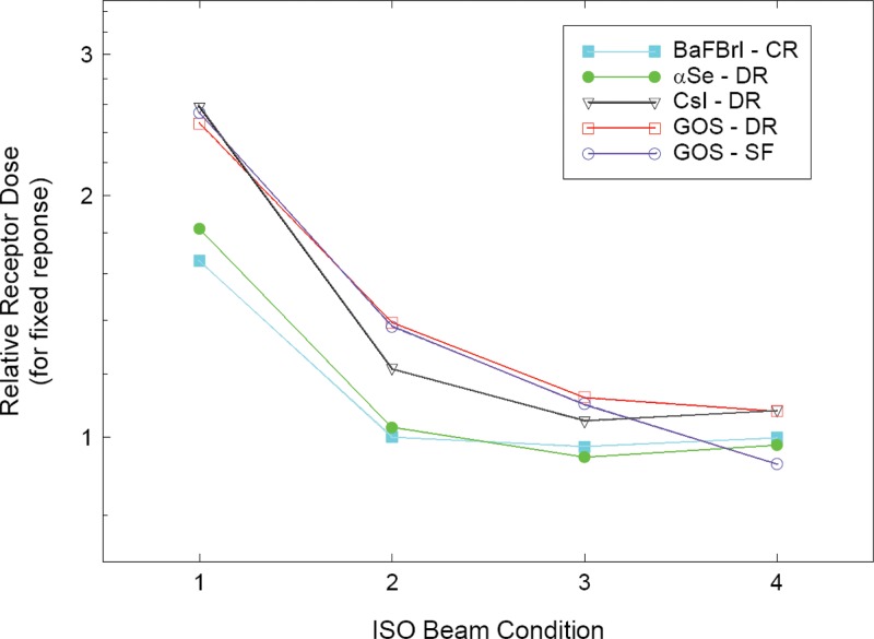
Techniques required to achieve optimal radiographic imaging in DR may be different from those used for film/screen imaging. In addition, different DR detectors may require different technique factors due to differences in the energy dependence of the detector materials in use.4 (See Fig. 1.) These technique differences between DR systems may cause confusion and suboptimal image quality at sites where more than one type of system is in use. Operators need a clear set of rules to produce consistent, high quality digital radiographic imaging based not on image density but on feedback regarding the detector exposure provided.
Figure 1.
Energy dependence of common detector materials (Ref. 4).
Several manufacturers currently use an exposure indicator which parallels the concept of “speed” or “speed class” used by film manufacturers. In addition, many manufacturers and users have become accustomed to characterizing their systems as functioning within a given speed class. This has created some misunderstandings and scientific inaccuracies which have been discussed in the literature.5
TG116 recommends avoiding the concept of speed class when referring to DR system performance. The definition of radiographic speed according to ISO 9236-1 is based on the radiation exposure required to achieve a net optical density of 1.0 on the developed film.6 With digital radiography there is no fixed relationship between the radiation exposure and the resultant density in the image. With film-screen detectors a change in speed may also result in a change in the spatial resolution properties of the detector. This same relationship does not hold true with digital detectors since sharpness is independent of the amount of exposure used to acquire the digital image.
The characterization of a digital radiographic system as being in a given speed class may give the false indication that it should always be operated at a specific exposure level. It may also give the false impression that the resulting digital image will have the same noise and resolution characteristics as those acquired with an equal speed class film/screen system. The digital system in reality can be operated over a broad range of sensitivity since the amount of radiation exposure determines only the level of quantum mottle and not the brightness of the image. From this context the level of radiation exposure, and thus the speed class, should be dependent upon the imaging task and upon the observer’s tolerance of image noise. As a general rule the ‘‘as low as reasonably achievable’’ (ALARA) concept should prevail in that the minimum amount of exposure, and hence, the maximum tolerable noise content, should be used to achieve the necessary diagnostic information.7 Using the speed class characterization for given digital imaging systems may increase the possibility that ALARA is violated for some imaging tasks.
An index of detector exposure is appropriate because it is reflective of the noise content, and thus the signal-to-noise ratio (SNR) in the image. For DR systems, the appropriate incident exposure is variable based on the desired signal-to-noise ratio rather than on the resulting optical density of a radiograph. Different digital detectors may require more or less radiation exposure to achieve the same noise content depending upon the DQE of the detector technology in use. For a given system, the image noise content will track inversely with the detector exposure. As radiation exposure to the detector increases, image noise will decrease and SNR will increase.
A standardized indicator of the exposure incident on a DR detector that is consistent from manufacturer to manufacturer and model to model is needed. This could be used to monitor differences in exposure between DR systems at a given institution, to compare techniques between institutions, or to estimate the quality of images from a given radiographic system. It could also provide quality control (QC) data if software is provided to record and retrospectively analyze exposure data from all systems.
A standard indicator which reflects the radiation exposure that is incident on a detector after every exposure event is appropriate. The detector exposure indicator is intended to reflect the noise levels present in image data. An adequate exposure is one that results in an appropriate noise level in the image as determined by the clinic where the system is in use. This report does not make recommendations on exposure adequacy, nor does the indicator represent exposure to the patient.
The task group considers the recommendations in this report to be achievable and important. It recognizes that a parallel standard was recently completed within the International Electrotechnical Commission (IEC), designated IEC 62494-1 Ed.1: Medical electrical equipment—Exposure index of digital x-ray imaging systems—Part 1: Definitions and requirements for general radiography. This IEC standard specifies the definitions and calibration conditions for the detector exposure indices of digital radiography systems. The leadership of Task Group 116 participated in this IEC effort since its inception and served as U.S. National Committee experts in IEC Working Group 43. The concepts and calibration conditions in the IEC working draft are consistent with those in this report. While the terminology and definitions in the IEC standard may differ in scale and nomenclature from those in this report, the IEC standard is completely consistent with this report. Absolute adherence to the nomenclature, symbols, and multiplicative factors of scale in this report are inconsequential to achieving the ultimate benefit of these recommendations as long as all manufacturers adhere to the IEC standard definitions. Users should be able to rely on a manufacturer’s claim of conformance to the IEC standard to identify equipment offering a standard exposure index as described in this report.
DEFINITION OF TERMS USED
Digital radiography systems utilize a series of computational processes to transform the raw data of the detector into an image intended for presentation. These processes include those used to assess the average response of the detector and its relation to the incident x-ray exposure.
The image formation process begins with the extraction of raw data from the detector immediately following an exposure event. Those data must be corrected for imperfections in the detector array such as the presence of bad pixel elements, dark current corrections, and gain corrections that may be applied on a pixel-by-pixel basis. After these corrections have been applied, the set of resulting pixel values are ready to be processed by the system and are referred to as “for-processing” pixel or Q values. The system then attempts to identify which of these pixels contain information that is of interest to the user, typically those that contain information relevant to the anatomy being examined. This process is called segmentation. It is from the segmented image values that TG116 proposes the exposure indicators be determined. The final image for display results from grayscale transformations, broad area equalization, edge restoration, noise reduction, or other image-related processes that are performed on the for-processing Q values resulting in “for-presentation” values. values are typically stored in a PACS and transmitted to a printer or workstation for display. The remainder of this section defines the terms used in this document that relate to digital radiography processes just described.
DR: Radiographic imaging technology producing digital projection images such as those using photostimulable storage phosphor [computed radiography (CR)], amorphous selenium, amorphous silicon, CCD, or MOSFET technology.
Standardized radiation exposure : The air kerma at the detector of a DR system produced by a uniform field radiation exposure using a nominal radiographic and specific added filtration resulting in a specific beam half layer value (HVL) (see Sec. 4).
- For-processing pixel values : For-processing pixel values are the image pixel values produced by a DR system after necessary corrections have been applied to the initially recorded raw data to compensate for these types of effects (see IEC62220-1 Ed.1 for a complete description of appropriate correction methods).7 The following corrections may be applied:
- Defective pixels may be replaced by appropriate data.
- Flat-field correction.
- Correction for the gain and offset of single pixels.
- Geometric distortion.
- The relationship between Q and may vary for different DR systems. Manufacturers are expected to provide access to Q data and to provide information on this relationship as a part of normal system documentation. Images with Q values would typically be processed by the DR system in order to produce images for presentation.
- Normalized for-processing pixel values : Normalized for-processing pixel values are for-processing pixel values Q which have been converted to have a specific relation to a standardized radiation exposure . Q values are converted to using the DR system’s relationship between Q and . After conversion of Q to , the relationship between air kerma at the input surface of the detector and the value is
where is in microgray units, , and .(1) - For-presentation image values : For-processing pixel values are typically modified by image processing to produce an image with values suitable for display . This processing generally determines the useful values for display and applies a grayscale transformation. The processing may also provide broad area equalization, edge restoration, or noise reduction.
- Indicated equivalent air kerma : An indicator of the quantity of radiation that was incident on regions of the detector for each exposure made. The value reported may be computed from the median for-processing pixel values in defined regions of an image that correlate with an exposure to the detector. The median value is then converted to the air kerma from a standardized radiation exposure that would produce the same detector response, i.e., result in the same median for-processing signal value Q in a predefined ROI. The regions from which the median is determined may be defined in different ways (see Sec. 5). The value should be reported in microgray units with three significant figures of precision.
- Image values of interest (VOIs): Pixel values in the original image that correspond to the region in the recorded image area for a particular body part and anatomical view. may be calculated from a subset of pixels within the VOI. Not all pixel values in an image are associated with objects that are of interest to the viewer for the purposes of diagnosis. Those that are of interest are referred to as the VOIs. The pixels that are associated with the VOI are typically identified based on their physical location and their relative signal strength characteristics. This identification process is referred to as segmentation. Specification of a standard method to be used for segmentation is not within the charge of this task group. Further, to recommend one standard method above all others may impede the development of more sophisticated methods that yield more stable results in the future. Detector values suitable for presentation are typically sent to display devices (printers or workstations) or image archives. DICOM standards, including DICOM PS3.14, define these as presentation values, or P values.8
- Target equivalent air kerma value : The optimum value that should result from any image when the detector is properly exposed. values will typically be established by the user and/or DR system manufacturer and stored as a table within the DR system. The table is referred to in this document as where b and v are table indices for specific body parts and views.
- Deviation index (DI): An indicator as to whether the detector response for a specific image, , agrees with . Relative exposure indices are to be reported as
with one significant decimal of precision (i.e., ). DI is intended as an indicator for radiographers and radiologists for whether or not the technique used to acquire a radiograph was correct. This definition results in a DI of 0.0 when the reported equals (a perfect exposure). The index changes by ±1.0 for each change of the reported .(2)
RECOMMENDATIONS
This report makes the following specific recommendations regarding the indicator of exposure for digital radiography systems:
It is recommended that all DR systems (regardless of detector design) provide an indicator of the x-ray beam air kerma (expressed in ) that is incident on the digital detector and used to create the radiographic image. This indicator shall be called the indicated equivalent air kerma . It is further recommended that the DICOM Standard incorporates a new element for digital radiography that is specifically defined as the indicated equivalent air kerma. The indicator value shall be included in the DICOM header of every image as a floating point value with three significant figures.
In addition to the indicated equivalent air kerma, it is recommended that the relative deviation from the value targeted by the system for a particular body part and view be reported. This index, the DI, should be prominently displayed to the operator of the digital radiography system immediately after every exposure and immediately after any modification of the detected image values of interest. It is further recommended that the DICOM Standard incorporate a new element for digital radiography that is specifically defined as the deviation index. This indicator value shall be included in the DICOM header of every image as a signed decimal string value between −9.9 and with one significant digit after the decimal.
The indicated equivalent air kerma and the deviation index are determined from the segmentation image pixels (see Sec. 5). It is recommended that systems provide display functions to optionally delineate the segmented image pixels as an overlay on the recorded image that is otherwise normally presented for approval by the operator. Additionally, this overlay region can be incorporated in any images exported for archive or viewing using DICOM services. DICOM Segmentation Storage SOP Class (Supplement 111) forms the basis for achieving this functionality.9 Alternatively, this could be accomplished with overlay and annotations that are part of Gray Scale Presentation State Storage objects described in DICOM Supplement 33.10
Vendors should provide appropriate analytical tools (see Sec. 11) and allow for-processing image data (Q values), or exposure values normalized to the standard beam conditions , to be displayed and analyzed on the system console. It is also important that the vendor allows these data to be exported in DICOM format for off-line analysis. To accomplish this, all DR systems should provide access to images containing for-processing pixel values Q. This can be provided by support for DICOM export services of DX for-processing images containing normalized for-processing values . Alternatively, images of either or Q can be made available in DICOM PS3.10 format on a media storage device.11
The relationship between values and the standardized radiation exposure incident to the DR detector is required for tests of system performance. It is recommended that this relationship be provided by the system manufacturer over the full range of radiation exposures that the system is capable of recording.
For tests of system performance, it is useful to view and analyze the for-processing image values of acquired test radiographs. It is recommended that systems provide functions to display images without image processing (i.e., Q values) and to report the mean, median, mode, standard deviation, and pixel count of values within graphically defined regions. Interactively drawn circular or rectangular regions are appropriate for this purpose.
For testing of systems, it is recommended that manufacturers provide methods to remove the antiscatter grid without otherwise changing the detector response or provide grid attenuation factors to be used in calibration.
STANDARD RADIATION EXPOSURE CONDITIONS
Standard beam spectrum
A uniform field radiation exposure made to the detector of a DR system is used to assess the relation between for-processing image values recorded by the detector and the quantity of radiation incident on the detector . The radiographic technique used to make the exposure is intended to provide a beam quality typical of that for most examinations for which the system is used. This is done by using additional filtration to emulate the beam hardening of a patient. This section recommends standardized radiation conditions to be used for this purpose and addresses only general radiographic systems.
The IEC and ISO have previously made recommendations for standard radiation conditions for use in testing medical diagnostic x-ray systems.6, 12, 13 A variety of conditions with different beam qualities are recommended and labeled with “RQA” prefixes. However, these conditions require thick filters composed of 99.9% aluminum which is impractical for field measurements. Alloy 1190 falls into the category of scientific grade (also called ultrapure aluminum) and is available only through specialty metal companies for a high price and in small quantities and limited form. Alloy 1100 is a 99.0% pure Al alloy that is widely available on the market.
The use of copper as a component of the added filtration is recommended in order to reduce the overall thickness of added material. In prior publications, 0.5 mm of Cu was found to minimize the variability in the response of a CR system as was varied within .14, 15 The addition of Al material allows a HVL near the desired nominal to be achieved while keeping the copper thickness at a value that is readily available from metal foil suppliers. The added Al material should be on the beam exit surface of the Cu so that any Cu characteristic radiation is absorbed in the aluminum.
Typically, clinical tubes in use at modern facilities contain enough filtration to exceed the IEC open beam HVL specification of 2.5 mm Al at (RQR5). If this is the case, the filtration to be added to the beam should be reduced to satisfy RQA5 by removal of all or part of the aluminum. If the open beam HVL falls below the specification of 2.5 mm Al at , the filtration to be added to the beam should be increased to satisfy RQA5 by addition of up to 4 mm of aluminum. If the unfiltered beam is generated using exotic added filtration, it is recommended that added filtration be replaced with enough aluminum to meet the requirements of RQR5. The may also be adjusted, if necessary.
Added filtration with 0.5 mm of copper plus 3–4 mm of aluminum is suitable for x-ray tubes with modest intrinsic filtration. For an unfiltered x-ray tube spectra with HVL of 2.58 mm Al at (RQR5), computational simulations (see Appendixes A, B) indicate that a similar beam quality with Al is obtained using added filtration of either 21 mm of pure aluminum as specified for RQA5, 0.5 mm Cu plus 3 mm Al (type 1100), or 24 cm of muscle.
The following types of brass (30%–50% zinc with traces of tin) are also considered acceptable to be used in place of the copper: Admiralty brass (30% zinc and 1% tin), alpha brass (less than 35% zinc), alpha-beta brass or duplex brass (35%–45% zinc), arsenical brass or DZR brass, beta brass (45%–50% zinc), cartridge brass (30% zinc), common brass or rivet brass (37% zinc), high brass (35% zinc), low brass (20% zinc), naval brass (40% zinc brass and 1% tin), red brass (gunmetal), or yellow brass (33% zinc). Use of leaded brass, aluminum brass, white brass, or gilding metal is not recommended.
For the first edition of IEC 61267, was to be adjusted to achieve a desired beam HVL.11 For the second edition, more stringent constraints were placed on the beam quality before added filtration rather than allowing adjustments. As a consequence, the conditions recommended in the second edition are applicable only to laboratory facilities. It has also been reported that CR system response varies by approximately 10% over a limited a range of kV.14 Measurements made by TG members on a variety of clinical systems (both CR and DR) indicate that system response is very consistent within the recommended ranges of HVL, kV, and added filtration (see Appendix B). System response in terms of for-processing signal per unit exposure varied by less than or equal to 6% with /filter combinations as low as with 0 mm Al (5.93 mm Al HVL) to with 8 mm Al (8.62 mm Al HVL). Similar results have been found by others and reported in the literature (see Fig. 1).4 For this limited range of kV, 5% tolerance seems reasonable.
While use of the RQA5 beam is acceptable for calibration, TG116 recommends standard beam conditions using copper foil and highly available type 1100 aluminum with a specified range whose accuracy has been independently verified to be within 3% of the indicated value (see Table 1). The target HVL is intended to be reasonably close to RQA5 . Minor adjustments in indicated and added filtration are permitted to achieve the target beam quality. While not required, it is acceptable to vary the by up to ±5% and the amount of added aluminum within the listed range to achieve a beam quality that is as close as possible to the listed target HVL. The generator used for the standard beam must be capable of maintaining a constant kV throughout the entire exposure.
Table 1.
Standard beam radiographic conditions.
Type 1100.
Standard beam geometry and calibration verification procedure
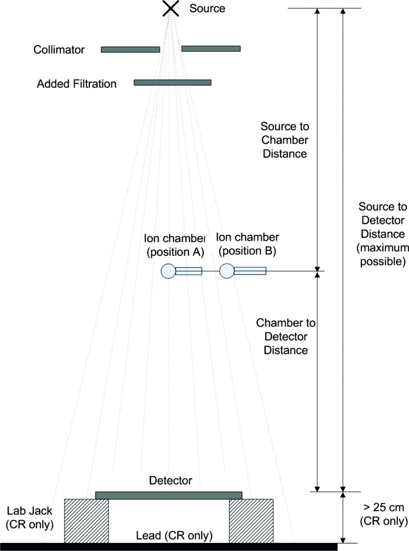
This section describes the measurement geometry to be used to determine under the standard radiation exposure conditions shown in Fig. 2. The steps to use when making these measurements are summarized below.
-
(1)
Prior to any measurements verify that the x-ray source has acceptable exposure reproducibility (coefficient of variation ) and kV accuracy (±3%) at the standardized condition. During any exposure for which an image is not acquired, the image receptor should be protected from exposure to the primary beam.
-
(2)The detector should be placed as far from the x-ray source as is practical, at least 100 cm.
- (a)
-
(b)If present, and if possible, remove the antiscatter grid and any other system components present between the ion chamber and the image detector without otherwise modifying the response of the detector. If any components cannot be removed, obtain the attenuation factors from the DR system or component vendor.
-
(c)If the detector is not square, the long axis of the detector should be perpendicular to the x-ray tube anode-cathode axis.
-
(3)
Place a calibrated ion chamber at the center of the beam approximately midway between the source and detector (see position A in Fig. 2). The distances should be measured to the center of the chamber and to the surface to the detector. The distance from the x-ray source, to the center of the ion chamber, and to the surface of the detector must be known. If the distance from the detector housing surface to the detector is not labeled consult the manufacturer for this measurement.
-
(4)
Collimate the x-ray beam to only cover the ion chamber with no more than 1 in. margins.
-
(5)
Add 0.5 mm copper filtration at the face of the collimator.
-
(6)
Cover the detector with a lead attenuator or similar barrier to preclude exposure to the detector. Measure the HVL of the filtered beam and adjust the and/or aluminum filtration within the limits specified in Table 1 to obtain a HVL as close as possible to 6.8 mm Al.
-
(7)
Make an exposure and determine the air kerma at the detector using an inverse square correction and applying the grid attenuation factor, if appropriate. Repeat the exposure at a new setting that will deliver the desired air kerma to the detector. In general, the desired air kerma will produce a value of that is in the middle of the detector response range.
-
(8)
Move the ion chamber perpendicular to the tube axis such that it is outside the detector field of view (see position B in Fig. 2).
-
(9)
Remove the filtration and open the collimator so the x-ray beam will cover the entire detector and includes a margin large enough to cover the ion chamber. If the system does not allow the collimator to be opened beyond the detector size, open the collimator as large as possible and place the ion chamber as close to the edge of the x-ray beam as possible within the field of view of the detector. Ensure that the entire ion chamber is in the radiation beam and is not shadowed by a collimator blade. Replace the filtration.
-
(10)
Remove the protective lead apron and make an exposure using the found in step (7) above. Determine the ratio of the air kerma at position A to that at position B.
Figure 2.
Standard beam geometry.
When making standardized radiation exposures using this geometry, the air kerma recorded by the ion chamber is converted to for each exposure using the ratio determined and the inverse square correction. Some manufacturers have specified other requirements in addition to beam quality, such as readout time delay after exposure with CR systems. These requirements should be adhered to as long as the standard beam conditions specified in this part are not affected.
ASSESSMENT OF INDICATED EQUIVALENT AIR KERMA
It is expected that manufacturers of DR systems will establish the relationship between for-processing image values and standardized radiation exposure , i.e., Q as a function of . This relationship should be specified over the full range of exposures for which the system is designed to respond. If individual systems vary in response, information provided with the system should include the acceptable variation specific to a particular system. As a part of acceptance testing, physicists may wish to verify this relationship by recording images of a uniform field obtained using standard beam exposures made with an appropriate set of values.
For validating Q as a function of , the incident air kerma should be measured using the methods described in Sec. 4B for which reflects the radiation incident to the central region of the detector. For each image recorded, either the for-processing image pixel values Q or the normalized for-processing image pixel values should be analyzed to determine the median value from a central region of interest ( and ).
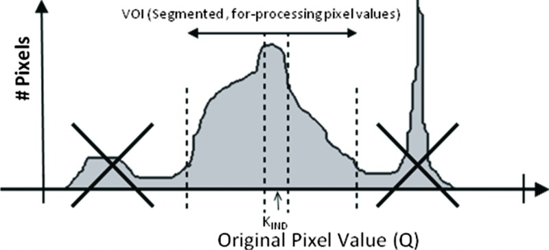
For determining the indicated equivalent air kerma from an individual clinical image, is computed as the corresponding to the value in a defined region of a recorded image (see Fig. 3). The median of image values is computed and transformed using the known relationship between for-processing image pixel values and exposure. The median is recommended rather than the mean or mode because it is less affected by data extremes and outliers. Rectangular or circular regions having an area greater than or equal to about 4% of the active detector area should be used. The median value can be determined using vendor-supplied analysis tools designed specifically for evaluating the test image or by exporting the test image as a DICOM object to an external workstation for evaluation. The median Q value and the median value are thus the same as long as the transformation is monotonic. Additionally, the median value can be determined from the histogram of values within the defined region.
Figure 3.
Example of a method to determine from an analysis of the image histogram. (Courtesy of Agfa Medical Imaging.)
The region used to compute should be defined such that the indicated equivalent air kerma reflects the median exposure within the segmentation image pixels in the recorded image. The segmentation image pixels will vary depending on the purpose of the radiograph. For example, the primary anatomic region of interest in a chest radiograph is the lung parenchyma whereas the mediastinal and subdiaphragmatic portions of the image would be secondary regions. However, the mediastinum would be a primary region for a thoracic spine radiograph. Hence the segmentation image pixels for the PA chest exam and for the PA T spine, even if collimated identically, would not comprise the same set of image pixels.
For some existing systems the segmentation image pixels are defined by the portions of the image for which body tissue has attenuated the beam. Unattenuated regions of direct exposure are excluded along with regions outside of the collimated primary beam that receive only scattered and off-focus radiation. Other systems have used geometric regions (circles, rectangles, etc.) positioned in the general area of the primary anatomic region. These can be systematically placed in the field such as for the position of a central automatic exposure control (AEC) cell.
More robust scene recognition algorithms may be used to identify the segmentation image pixels. Robust region definition methods typically require advanced image segmentation algorithms that have generally not been fully disclosed by manufacturers. In most cases, these methods occasionally fail under certain clinical conditions. To aid users in identifying recordings for which the segmentation may have failed, it is recommended that systems provide functions to display an overlay of the segmentation image pixels. If provided, this overlay should be accurately registered to the image pixels. Additionally, methods to modify the selection of segmentation of the image pixels after the automated segmentation algorithm is performed should be provided.
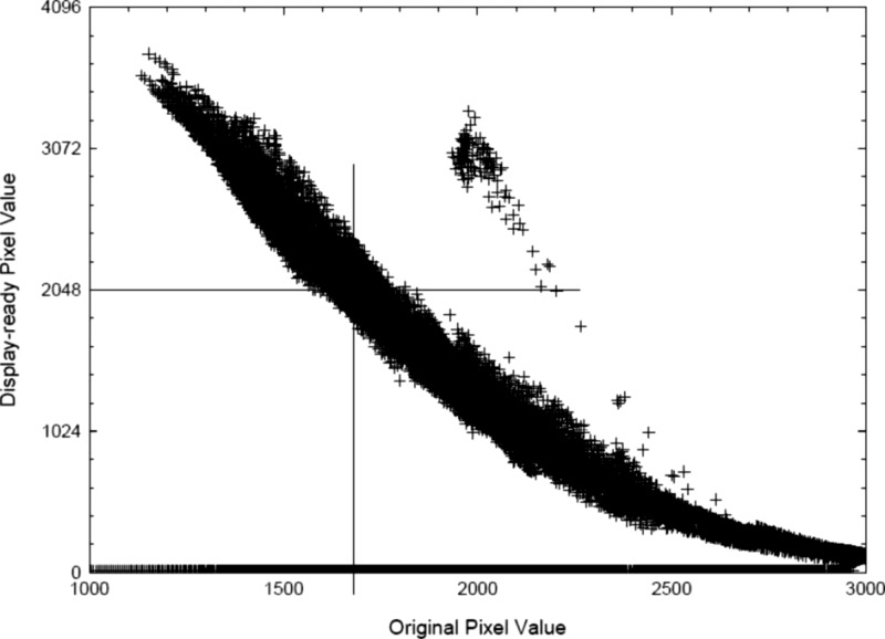
For many systems, region definition is used to identify that portion of the image that should be rendered in the midportion of the grayscale transformation. In recent reports, it has been suggested that the for-presentation image pixel values be used to define the region for computation of .16 In this work, pixels of the for-presentation image within a fixed range of presentation values are used to define the region for computation of (see Fig. 4). For example, presentation values from 45% to 55% of the full range of values are in the midgray regions of the image, which normally correspond to the anatomic regions of highest interest to be rendered with maximum contrast. The value of is computed from pixels in the for-processing image that correspond to this range. Regardless of the method used to define the region that is used to compute , its value should reflect any changes to the segmentation image pixels that are made by the operator.
Figure 4.
Example of a method to determine from of a processed image (Ref. 16).
This report does not make recommendations as to how the segmentation image pixels are to be defined. Rather, the scope of recommendations is restricted to recommendations directed at standardizing the terminology and beam conditions associated with reporting indices of exposure. It is expected that conformance in these areas can be achieved in the near future. The TG recognizes that the defined region from which is computed has strong influence on the result. A completely satisfactory solution for this difficult engineering problem remains unidentified. In light of this, the consensus of the TG is that it would be inappropriate to limit further development of more robust segmentation algorithms by establishing a standard method for defining segmentation pixels at this time.
The indicated equivalent air kerma is an indicator of the detector response in regions where anatomically important tissues have been recorded by a DR detector. is not equal to the incident exposure for the radiograph recorded. Rather, it is associated with the incident exposure from a standard reference beam that would have produced the same detector response. For this reason, it is referred to as an “equivalent” air kerma. For the general radiography standard beam conditions, the incident exposure required for the same receptor response in a typical DR detector varies modestly for peak tube potential values in the range from 55 to .4 In general, the actual incident exposure required to produce the same detector response will change with varying tube potential for radiographs of a specific object.
REPORTING DEVIATION INDEX
For radiographs of different body parts and/or views, the value of required to obtain acceptable image quality may vary. Additionally, the purpose and clinical diagnostic indications expected for a particular procedure may influence what is considered acceptable. For this reason, it is recommended that manufacturers automatically reference the appropriate standard beam condition (based on body part and anatomical view) when determining and deduce the recorded relative exposure from the appropriate in relation to that targeted for the body part and view of the radiograph.
The DI is intended to indicate the acceptability of SNR conditions in the segmentation image (as compared to high or low) to persons performing or interpreting radiographic examinations. How this index is calculated and the information displayed to these groups have an influence on how it is interpreted. Several options were considered by the TG for the nature of this index. Some were of the opinion that an index that varies linearly with would be more understandable to both radiologists and technologists. However, this approach suffers from the fact that such an index would asymptotically approach 0 as exposures decreased to 0, thus minimizing the apparent impact that underexposure has on image quality. Another consideration is the fact that image noise is logarithmically related to exposure. For underexposed images, use of a linear indicator would not reflect the magnitude of the change necessary to bring about a corresponding improvement in noise. It was decided that a logarithmic scale in base 10 would provide appropriate information in terms of both direction (overexposure or underexposure indicated by a positive or negative value, respectively) and magnitude ( is approximately 125% of the intended exposure, −1 is 80% of the intended exposure) on needed technique corrections. An exposure resulting in a DI value of would require an adjustment of −1 step on the density or control of a properly calibrated modern radiographic system.
Tables of targeted values may be provided by manufacturers with values reflecting typically acceptable values for the detector technology being used. Typically, these will be lower for detector technology that has higher detective quantum efficiency. Provisions must be available for imaging centers to adjust the values based on an individual facility’s criterion for image quality. Systems should provide a mechanism to export and import tables in a consistent format so that tables could be shared between imaging facilities using the same DR system. A process for updating the tables of all systems within a facility that is managed via a network would be extremely valuable so that changes in values can be readily disseminated to distributed systems. DR systems should also provide the means to automatically save the associated for any body part and view as the default target value when invoked by an appropriately privileged operator.
CLINICAL USE OF THE DEVIATION INDEX
The clinical use of the deviation index is essentially the same as that of film optical density: It serves as an indicator of proper radiographic exposure. For film/screen images, the optical density of the image itself is used to indicate proper exposure according to the clinical preferences of the facility. By delinking image appearance (in terms of brightness or contrast) from the amount of radiation exposure used to produce it, digital imaging alleviates the dynamic range limitation suffered by film. The drawback is that the direct visual feedback as to proper exposure is also severed. As has been noted before, the result can be widely varying clinical techniques, with consequences to both image quality and patient radiation exposure. The primary concern with DR image quality as it relates to detector exposure is with image noise (quantum mottle). DR postprocessing and “QC” workstations generally utilize displays of lower resolution ( or less) and lower brightness and capable of rendering fewer gray levels than those to be used for primary diagnostic interpretation. These “secondary”17 workstations are also rarely calibrated to DICOM PS3.14. As result, it is often the case that image noise is not well appreciated on such displays. What might appear acceptable on the QC workstation may be diagnostically unacceptable to the radiologist reading on a display calibrated to DICOM PS3.14. The deviation index can be used clinically to ensure that the amount of radiation delivered to the detector and, hence, the noise content in the image, is appropriate for a given imaging task.
The reader should be cautioned that possible system errors in the segmentation may cause the DI to incorrectly reflect the adequacy of the exposure. Causes of errors in segmentation will vary by vendor—some examples include the presence of prostheses or gonadal shielding, failure in identification of collimated area due to scatter or off-focus radiation, and unexpected positioning of a body part in the field of view. Poorly defined collimation may lower the DI, depending on the exam and projection. Undercollimation that causes unusually large amounts of the image to be unattenuated by the patient may increase the DI. Both of these interferences can result in a false DI. If any of these is the case and the reported DI is out of the acceptable range, a repeated exposure may not be necessary. The technologist should closely scrutinize every image for noise content, using zoom and pan utilities if available. DI values should be treated more like a guide instead of an absolute measure of image quality. Until segmentation becomes more robust, the technologist should judge image quality on noise content and not depend solely on the exposure index value.
EXPOSURE INDICATOR AND RADIOGRAPHIC TECHNIQUES
The indicator serves as a means of establishing appropriate radiographic techniques which might otherwise drift widely from desired levels. Adhering to target ranges for the particular deviation index values can be a valuable tool for standardization and stabilization of manual techniques. For departments involved in clinical aspects of radiologic technology training programs DI can also be used as an aid to instruct students in proper manual technique selection and for evaluation of trainee performance in this regard.
DI values are determined for each body part and anatomical view being imaged on an exposure by exposure basis by comparing the value for a given exposure to the target values stored on the system. These values are the optimal exposure values determined either by the vendor or by the site system administrator for each body part and anatomical view being imaged. The values should be set according to clinical preferences and specific exam needs. This approach is consistent with maintaining exposures in a range that is ALARA. The values associated with each body part and view, if present, should automatically be invoked when the body part and view for postprocessing are selected by the operator at the processing system console.
Once levels are set, it is useful to identify several types of “control limits” on DI: A target range, a “management trigger” range, or a “repeat” range (see Table 2). The reason for this is that unlike filmed images, in which inadequate or excessive image optical density is a determinant of when a repeated film is needed, the reason for repeating a digital image is primarily noise related. What would be an underexposed film image may be of adequate diagnostic value in digital form. Similarly, it is never appropriate to repeat overexposed digital images unless analog-to-digital converter saturation has occurred which may cause relevant parts of the image to be “burned out” or “clipped” (that is, all pixels in the affected region are forced to the maximum digital value and thus containing no information) or contrast to be affected in excessively exposed regions of the image. Since this judgment depends upon the diagnostic task, it is appropriate to seek consultation with a radiologist for certain ranges of DI-indicated underexposure and overexposure prior to repeating.
Table 2.
Exposure indicator DI control limits for clinical images.
| DI | Range Action |
|---|---|
| Excessive patient radiation exposure: Repeat only if relevant anatomy is “burned out,” require immediate management follow-up | |
| to | Overexposure: Repeat only if relevant anatomy is burned out |
| −0.5 to | Target range |
| Less than −1.0 | Underexposed: Consult radiologist for repeat |
| Less than −3.0 | Repeat |
A properly functioning AEC system will produce optical densities of OD under varying combinations of and phantom thickness (adjusting mA to result in exposure times greater than 10 ms).18 For a film/screen combination, optical density in the straight-line portion of the H&D curve is related to detector exposure (or ) as follows:
| (3) |
Combining Eqs. 2, 3, the range of deviation indices corresponding to a given OD range would be
| (4) |
For a film/screen combination with a gamma of 2.85 (a fairly common gamma in clinical use), the acceptable DI range would be
The TG recommends the action levels shown in Table 2.
To be effective, care must be taken to assure that appropriate targets and limits are posted and the radiographers are educated and periodically re-educated as to their meaning. A substantial deviation from the established target range should require management oversight to determine the cause for the deviation and implement appropriate corrective action such as retraining, recalibration of the equipment, or reassessment of the target value. Operators should be instructed that high DI values are associated with excessive radiation dose but have good image quality with respect to noise. Tighter limits on DI may be difficult to achieve in practice due to variations and drifts in CR reader calibration (especially with multiple readers), variations between detectors, as well as traditional differences between x-ray rooms (generator design, calibration, and tube filtration).
AND AUTOMATIC EXPOSURE CONTROL SYSTEMS
In regard to maintaining appropriate image quality and patient exposures, it is clear that AEC systems are just as important to digital imaging as for film/screen imaging despite the wide dynamic range of DR. Regardless of detector type, AEC systems are designed to (and must be appropriately calibrated to) terminate an x-ray exposure once a predetermined radiation exposure is recorded at the detector. Like film/screen systems, digital detectors have energy dependence, which in general differs from that of the AEC sensors (see Fig. 1).4 Depending on design and calibration of the AEC, the result can be digital image levels that vary from the desired level.
A well-designed AEC should be capable of modifying required detector exposures based on exposure conditions (typically selected and mA) to compensate for energy dependence and exposure rate and thereby maintain a consistent image signal-to-noise ratio.19 Assuming that AEC performance is evaluated under clinically relevant conditions which can be simulated by various thicknesses of acrylic and ranging from 60 to 120,19 the can serve as the indicator of image signal level for this purpose, just as optical density did for film. Adequate AEC performance with film/screen is considered to be a density variation of ±0.15 OD on a system using film with a gamma of 2.5. For equivalent performance on a DR system using AEC, one would expect to remain constant with varying thickness and (adjusting mA to result in exposure times greater than 10 ms) within ±7%.
In using during AEC performance evaluation, several caveats must be noted. First, the may be associated with a different image region from that used by AEC sensors; second, the size of the area used by determination may introduce different field sizes and energy-related effects from those affecting the AEC; and third, many of the conventional radiographic systems used with DR were designed to compensate for film/screen energy dependencies and may not be capable of providing constant response for DR.
Many radiographic systems in use today incorporate AEC systems designed for use with film/screen systems and may allow for energy compensation appropriate for film/screen. Such compensation may be hard-wired and unalterable or may have insufficient ability to compensate appropriately for DR. In particular, it is often the case that tends to be higher for AEC-based exposures at lower because the AEC compensation intended for rare-earth film/screen systems overcorrects for lower .20 If this is the case, values for DI may need to be adjusted upward to appropriately reflect this energy dependence.
Appropriate ranges for AEC performance evaluation must therefore take into account the age and pedigree of the radiographic system. Derived limits for AEC testing are equivalent to those that are used for film (for example, ±0.15 optical density units).21 Certainly, the much narrower latitude of film/screen calls for fairly tight AEC performance limits for reliable clinical results. Although desirable for DR as well, this may not be achievable in practice at this time.
INAPPROPRIATE CLINICAL USE OF DI
A final note regarding DIs and clinical techniques: Even if images being produced clinically have corresponding DIs well with the target range, the clinical techniques used may still not be appropriate. One can just as readily achieve an acceptable DI for an AP L-spine view with as with ; evidence of underpenetration and concomitant excess patient exposure with the lower may be clear from the contrast and underexposure of the spine regions but may be windowed/and leveled out in a digital image. Similarly, poor collimation, unusual patient body habitus, the presence of prosthetic devices, or the presence of gonadal shielding in the image may raise or lower DIs (depending on the exam and projection) and perhaps hide an inappropriate technique.22, 23, 24, 25 It is essential that all aspects of good clinical technique be adhered to and an appropriate DI value should not be interpreted as proof of good work.
RECOMMENDED OPTIONAL FEATURES
In addition to implementation of this standardized exposure indicator, there are opportunities for other useful tools to facilitate presentation of image processing-related information and improve the overall quality of the imaging operation. For instance, Sec. 3 calls for an overlay that graphically illustrates the pixels in a given image which have been used to calculate . This is intended to provide a very quick method of determining that the automated segmentation software performed correctly for any image. A similar feature would be to create a pop-up display of the Q histogram with the locations of the segmentation image pixels minimum and maximum overlaid on it showing the minimum and maximum Q values used for determination. Finally, there are many clever ways to indicate the DI for every image using a sliding bar or color coded tool with position and or color linked to the magnitude of DI.
Other highly desirable features are logs of the DI values and logs of the reasons for rejected and repeated images stored on the system. The anatomical view selection and technique factor information for every rejected image as well as the images themselves should also be stored on the system. Software to analyze these logs to assist with process improvement by identifying potential problematic exams, problems with equipment, and technologists in need of continuing education is also invaluable to the user community.
As already mentioned in Sec. 3, systems should provide a mechanism to export and import tables in a consistent format so that tables could be shared between imaging facilities using the same DR system. A process for updating the tables of all systems within a facility that is managed via a network would be extremely valuable so that changes in values can be readily disseminated to distributed systems.
For each clinical mode of operation other than general radiography for which a system is designed, the calibration conditions should be specified by the manufacturer (see Sec. 12). The manufacturer should also provide the following:
Filter(s) to be utilized for establishing for general radiography as well as for other modes of operation and should specify which body parts and views are associated with each filter (see Sec. 12).
A means to readily mount/dismount the filter(s) on an x-ray collimator.
mA, time/, SID, grid or no grid, and system protocol settings for calibration conditions.
The grid transmission factor associated with each beam condition (if present).
Exact specification of how to configure the system to obtain the for-processing image data.
Written, step-by-step calibration protocol and recommended frequency of calibration.
Full disclosure of the values associated with each body part and view.
Specification of the accuracy and reproducibility of the for the standard beam condition and the expected change in for other beam conditions.
The task group strongly recommends implementation of all of these ideas and anticipates the creation of many more once the efforts of the equipment manufacturing community are brought to bear on these issues.
APPLICATION TO DEDICATED CHEST, MAMMOGRAPHY, VETERINARY, AND DENTAL RADIOGRAPHY
is intended to be used as a measure of image quality with respect to image noise. For low energy x rays, more incident radiation is required to create the same detector response as for high energy x rays. The variation in detector response for values between 55 and 90 is sufficiently small to make an effective indicator of image quality with respect to the recorded noise in the image.4 For higher energies, this may not be the case. To maintain a consistent relationship between image noise and the indicator, it is possible that two standard beam conditions could be defined, one for imaging of the chest at tube potential settings above and one for all other radiographic images. This higher energy standard beam should be reasonably close to RQA9 (see Table 3).
Table 3.
A standard beam condition for dedicated chest imaging systems.
| Application | Added filtration | Target HVL | IEC surrogate | |
|---|---|---|---|---|
| Dedicated chest | 114–126 | 1 or 40 mm pure Al | 1 | RQA-9 |
Type 1110.
For a tube with HVL of 5.00 at (RQR9), similar beam quality with is obtained with 40 mm of pure aluminum as specified for RQA9 or with 1.0 mm Cu plus 4 mm of Al (type 1100). If 11.6 mm Al HVL cannot be achieved at with the recommended filtration, the additional aluminum filtration may be reduced and the adjusted to achieve the required HVL.
Digital mammography, veterinary, and dental radiography can all potentially benefit from a universal exposure indicator for the same reasons discussed in this report. Digital radiography in these fields suffers the same problems with manufacturer specific exposure indices from which DR suffers. Application to these areas would require modification of the calibration beam conditions to reflect the differences in typical beam attenuation and beam energies in clinical use.
The conditions for general radiographic systems differ substantially from those for mammography systems. Developing a universal exposure indicator for mammography would be useful for providing technologists feedback about exposure adequacy, especially for institutions with digital mammography units from different manufacturers.
APPENDIX A: RQA-5 VS TG116 STANDARD BEAM CONDITIONS, XSPECT 3.5B COMPUTATION SIMULATION
Simulation of standard beam conditions
Computational simulations using the XSPECT toolkit were used to simulate
the x-ray spectrum emitted by typical x-ray tube and collimator assemblies,
the attenuation of the spectrum by various amounts of added filtration,
- the half value of the x-ray spectrum,
- incident on the added filtration and
- incident on a detector;
and the signal and noise of a digital radiography detector.
For x-ray source conditions, three x-ray sources were considered based on their HVL at :
-
(A)
IEC RQR5 (2.58 mm Al, , Al intrinsic filtration).
-
(B)
Henry Ford Health System (HFHS) Rm 3 (3.02 mm Al, , Al/Cu intrinsic filtration).
-
(C)
HVL 4 (4.00 mm Al, , Al/Cu intrinsic filtration).
Source A is a lightly filtered source based on the IEC RQR5 specifications. Source B is based on a clinical system at HFHS for which the HVL has been experimentally measured. Source C is a hypothetical system with relatively heavy intrinsic filtration.
For added filtration, three added filtration configurations were considered:
-
(A)
21 mm aluminum (99.9%, RQA5).
-
(B)
0.5 mm copper and 2.8 mm aluminum (99.0% Al).
-
(C)
24.5 cm muscle [National Bureau of Standards (NBS) muscle composition].26
Added filtration A is based on the RQA5 standard and filtration B on the TG116 standard. For filtration B, the aluminum thickness is specified as 2.8 mm based on results indicating that the HVL matches at the same . The added aluminum was iteratively changed to determine this value. Additionally, the relation between added aluminum and the needed to obtain a HVL of 6.8 was determined. Similarly, 24.5 cm of muscle is chosen to match the HVL at the same .
The results are summarized as follows:
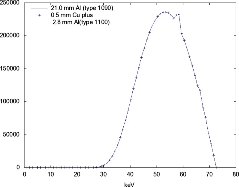
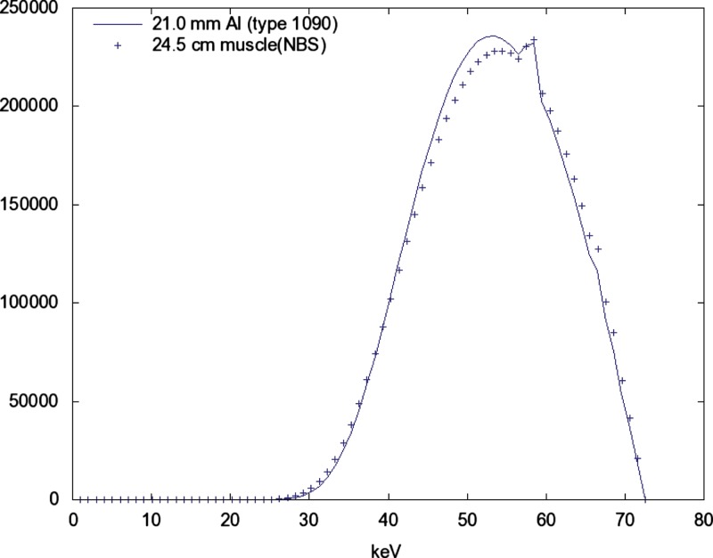
The three added filtration conditions produce nearly identical spectra at the same when the is adjusted to obtain a HVL of 6.8 (see Figs. 56).
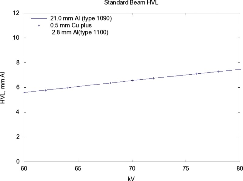
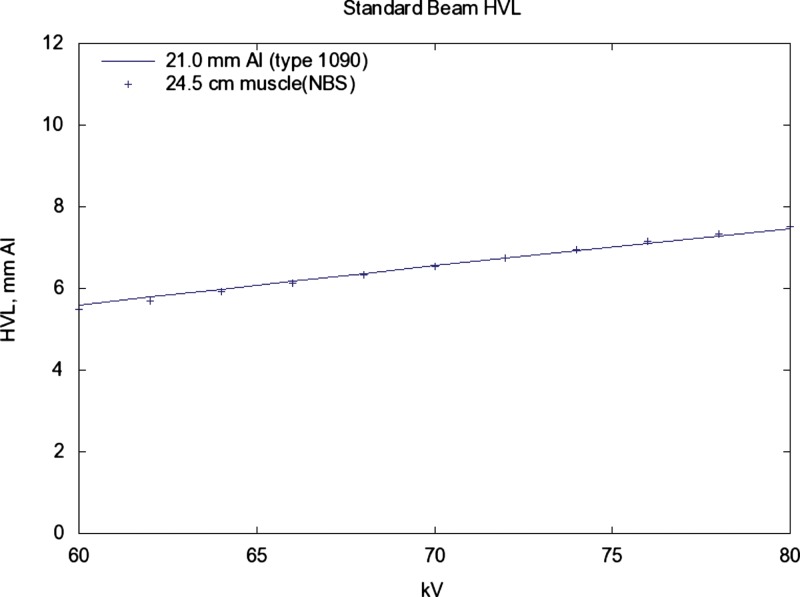
The HVL increases/decreases by about 0.1 for a change (see Fig. 7).
The for which a HVL of 6.8 is produced is related to the HVL of the source with a slope of −2.5 kV/mm ( at 2.58, 72.6 at 3.02, 70.1 at 4.00 mm). See Fig. 8.
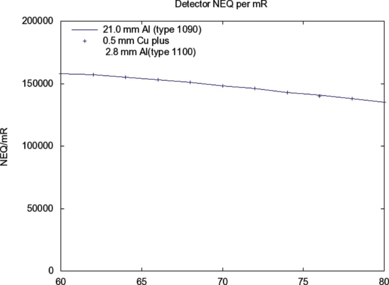
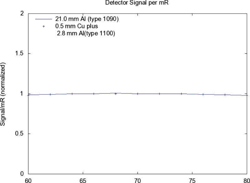
The detected signal and SNR in relation to is nearly identical for added filtrations A and B above (see Figs. 910).
Figure 5.
Using a source with , , the spectra for alternative additive filtrations are shown. The spectrum with added filtration 21 mm of aluminum (Type 1090, 99.9%) is shown as a solid line. The spectrum with added filtration of 0.5 mm of copper plus 2.8 mm of aluminum (Type 1100) is shown as points. The points have been reduced by a factor of 0.514 to produce the same exposure (mR) as the line. Both spectra have HVL=6.80.
Figure 6.
Same solid line as Fig. 5. Again, the spectrum with added filtration 21 mm of aluminum (Type 1090, 99.9%) is shown as a solid line. The spectrum with added filtration of 24.5 cm of muscle (NBS) is shown as points. These values have been increased by a factor of 43.7 to normalize the exposure.
Figure 7.
Same solid line as Fig. 5. The points are for 0.5 mm Cu plus 2.8 mm Al (1100) added filtration. The HVL of both is 6.8 at a kV of 72.59. For both, the slope of the relation with kV is 0.094 mm/kV. As a rule of thumb, a 1 kV increase will produce a 0.1 increase in HVL.
Figure 8.
Same source as in Fig. 5. The solid line shows the dependence of HVL on kV for 21 mm Al (1090). The points are for 24.5 cm muscle (NBS) added filtration. The sensitivity of HVL in relation to kV is slightly more compared with that for 21 mm Al added filtration.
Figure 9.
Same source as Fig. 5. The detected NEQ (i.e. ) for alternative additive filtrations are shown in relation to kV. The response for 21 mm added aluminum (Type 1090, 99.9%) is shown as a solid curve. The points are for 0.5 mm Cu plus 2.8 mm Al (1100) added filtration.
Figure 10.
Similar conditions as for Fig. 9, the detected signal (electrons) per incident mR (scatter free) as a function of kV is shown.
XSPECT computational tools
HVL (aluminum) were computed using the XSPECT toolkit for modeling x-ray transmission imaging. This toolkit contains programs for generating and modifying x-ray spectra stored in a common format. Utility programs modify the spectra to account for primary beam attenuation, unit conversion, and distance effects. Other programs compute the exposure in mR, the HVL of the x-ray spectrum, and the response of a detector in terms of the recorded signal and noise in units of electrons. The toolkit is presently being used in a graduate laboratory course on radiation imaging (NERS 580, University of Michigan, www.engin.umich.edu/class/ners580).
X-ray emission spectrum (SPECT_GEN)
X-ray emission spectra in units of photons/ are obtained from the SPECT_GEN module. In generating a spectrum, the user defines the , atomic number, tube angle, voltage waveform, and spectral increment. The program then generates a spectrum of bremsstrahlung and characteristic radiations and corrects them for self-absorption. The spectral calculations are based on equations from Storm27, 28 and contain empirical corrections for tube angle and voltage ripple. The results from XSPECT have been crosschecked for molybdenum and tungsten tubes against Fewell and Shuping’s data published by the FDA though the Bureau of Radiological Health.29
Primary beam attenuation (ATTEN)
Attenuation of the emission spectrum by various layers of materials is done using the program ATTEN that applies Beer’s law to the primary beam based on the material composition of the layer. Material compositions are stored in material files having a standardized format and maintained in a material library. Photoelectric cross sections for the elements were obtained from the work of Biggs and Lighthill.30 The coherent and incoherent cross sections were taken from the work of McMaster et al.31 For aluminum materials, type 1100 was used for 99.0% purity material and type 1090 for 99.9% purity material. Typical impurities were taken from matweb (www.matweb.com)
Entrance exposure (mR)
After the beam is attenuated, a simple inverse square law is applied to yield the spectrum at the entrance point to the patient. The MR program then computes the exposure at this point. The computation of exposure involved summing the product of energy fluence and the air energy absorption coefficient over the range of spectral energies.31 A conversion factor of 87.643 (ergs/gm)/R is used along with the air ionization factor of 33.97 J/C.
Detector response (DETECT)
The DETECT routine is used to compute detector signal by a weighted numeric integral of the x-ray energy spectrum incident on the detector assembly, (photons/):
where is the pixel area in and S has units of electrons/. The signal transfer efficiency, (electrons/keV), represents the average number of electrons produced in the detector by an incident x-ray with energy E. If equals 1.0 for all energies, the signal computed is that for an ideal energy integrating detector, .
The noise variance of the detector signal was computed using a similar integration (see equation above). The noise variance has units has units of . The noise transfer efficiency, , represents the average contribution to the signal variance of a pixel by an incident x-ray with energy E. The noise computed for an ideal detector is similarly obtained by setting . The signal-to-noise ratio, , is seen to be proportional to as expected
The accuracy of the signal and noise estimate computed by the DETECT routine depends on an accurate knowledge of the transfer efficiencies and . For this work, both were determined by using a Monte Carlo analysis to estimate the detector’s signal probability distribution function, , that describes the probability of collecting q electrons when an x-ray of energy E is incident on the detector. The detector tables for a thick selenium direct digital radiography detector were used in this comparison.
APPENDIX B: COMPARISON OF PURE ALUMINUM VERSUS COMMERCIALLY AVAILABLE TYPE 1100 AND 1190 ALUMINUM AND A COPPER/ALUMINUM ALTERNATIVE FOR RQA5
Introduction
Task Group 116 has recommended 0.5 mm copper (Cu) with 0–4 mm of alloy 1100 aluminum (Al) as an alternative x-ray beam hardener to obtain the same RQA5 spectrum as specified in IEC 61267:2005.12 IEC 61267 requires the use 99.9% pure aluminum for the RQA5 radiation qualities.
Alloy 1190 is a 99.9% pure Al alloy that meets the requirements of IEC 61267. In attempts to purchase alloy 1190, the authors were unsuccessful in finding an off-the-shelf source; alternatively alloy 1100 is a 99.0% pure Al alloy that is widely available on the market. Alloy 1190 is registered with 99.9% purity, which is higher than what is considered the highest purity commercial grade Al with 99.45%.32 Alloy 1190 falls into the category of scientific grade (also called ultrapure aluminum) and is available only through specialty metals companies for a high price and in small quantities and limited form.
What is currently unknown is the impact of using the widely available alloy 1100 compared with the specified alloy 1190.
Materials and methods
Since aluminum composition will vary from batch to batch and from the source of the raw materials, the first goal using simulation is to determine mixture compositions that reflect the maximum, minimum, and median attenuation possible for alloys 1100 and 1190. Since it is not possible to simulate all the possible combinations of elements in a specific batch, mixture modeling theory was used to select a reasonable set of mixtures as input to the simulation model to produce a prediction formula.
To perform the mixture modeling, the custom design platform in JMP 6 software (SAS Institute, Cary, NC) was used. A total of 1395 mixtures for each alloy using 30 elements were made in order to develop an accurate prediction formula.
Once the mixtures were selected in JMP, radiation quality simulation was performed using IDL 6.4 (IIT Visual Solution, Boulder, CO). The initial beam spectrum was calculated using the method developed by Boone and Seibert,33 and to this beam different filters were applied depending on the results desired. As the filters were applied, the attenuation was calculated with 1 keV interval from 1 to 70 keV.
The mass attenuation coefficients used in the simulation were taken from Cullen et al.34 with the exception of vanadium which was from the NIST mass attenuation coefficient data set.35 For a composite material such as alloy 1100, the linear attenuation coefficient μ was calculated according to the weight fraction of each element.
To determine the HVL for each Al Alloy mixture model, the initial x-ray spectrum was hardened to RQR5 with pure Al to achieve a HVL of 2.58 mm Al. Then the composition filter was added and a new beam spectrum calculated. Last the HVL was determined for the new beam using 100% pure Al. For the calculation of copper/aluminum filters, pure copper was used first and then the 1100 alloy.
Once simulated values were determined for each mixture, JMP 7 software (SAS Institute, Cary, NC) was used to develop a HVL prediction formula. Next the HVL for 5000 simulated batches of each alloy was generated using the HVL prediction formula.
Results and discussion
The numeric details of the distribution of the 5000 simulated samples of both alloys 1100 and 1190 are listed in Table 4. It is important to note that the standard deviation of alloy 1100 is 22.5 times greater than that of alloy 1190, but the ±3 standard deviation is still only ±0.0425 mm Al. The last line in the table shows the deviation of the mean from the RQA5 target of 6.8 mm Al.
Table 4.
Simulated HVL results from the various alloy batches.
| Pure Al | Alloy 1190 | Alloy 1100 | 0.5Cu/1Al | 0.5Cu/2Al | 0.5Cu/3Al | |
|---|---|---|---|---|---|---|
| Mean | 6.7638 | 6.788 5 | 6.880 3 | 6.656 7 | 6.753 9 | 6.846 0 |
| Std. Dev. | – | 0.000 629 3 | 0.014 166 4 | 0.000 760 4 | 0.001 442 4 | 0.002 056 2 |
| Mean target | −0.0362 | −0.011 5 | 0.080 3 | −0.143 3 | −0.046 1 | 0.046 |
From the simulation results, we see that the HVL using pure Al is slightly lower than the target of 6.8, but the rounding to one decimal point is 6.8. Out of all alloys tested, 1190 provides a HVL that is the closest to the target with a mean difference of just 0.01 mm Al. The standard deviation is negligible so it can be expected that any batch of alloy 1190 would produce a HVL value rounded to 6.79 mm Al. HVL for alloy 1100 had a noticeable shift from the target of 6.8, which may be attributed to the addition of Cu and iron (Fe) to the alloy. With a range of 6.8803±0.0283 mm Al covering 95% of all batches, we have a range of 6.8525–6.9081 mm Al. The 0.1 mm Al error margin is acceptable for clinical use and well within the ±0.25 mm Al proposed by Task Group 116.
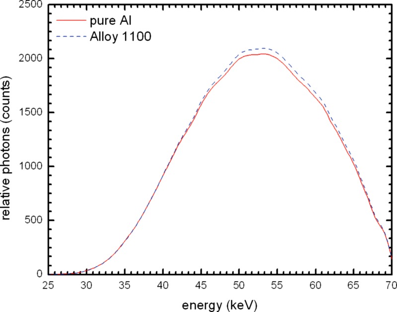
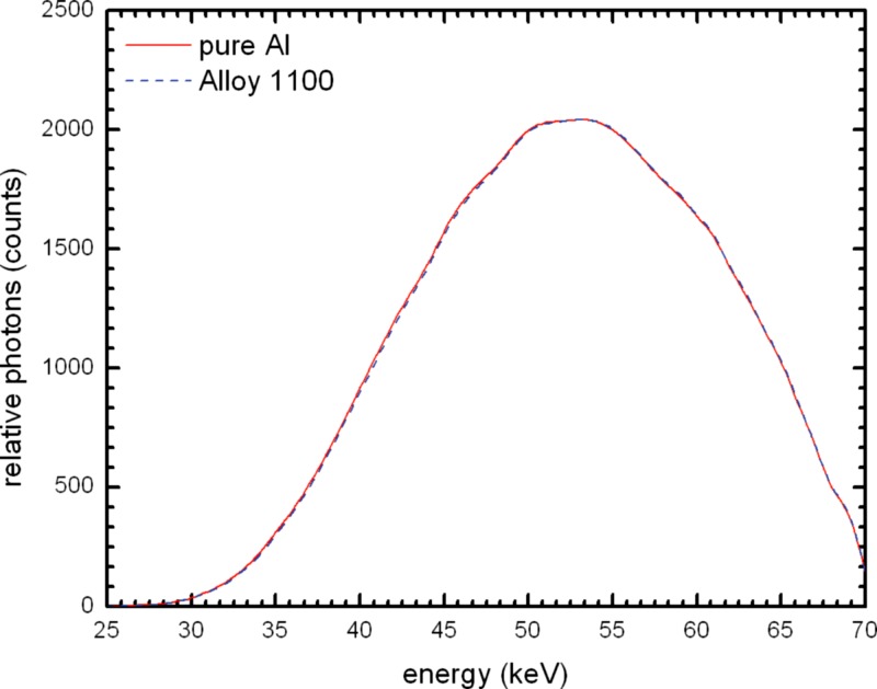
Figure 11 shows the comparison between the mean beam spectrum for alloy 1100 and that of pure Al. Alloy 1100 absorbs slightly less radiation, and the beam quality is shifted slightly harder. This can also be seen in Table 4 with the mean having a difference of 0.1165 mm Al. A normalized plot of the two spectra (Fig. 12) makes it easier to see the difference in beam hardness.
Figure 11.
Simulated beam spectrum comparison of 21 mm 100% Al and the mean of 21 mm alloy 1100 at .
Figure 12.
Simulated beam spectrum comparison of 21 mm 100% Al and the mean of 21 mm alloy 1100 at normalized to the 100% Al spectrum to allow for better visualization of the differences.
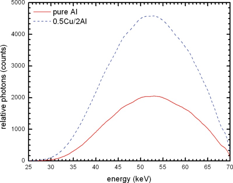
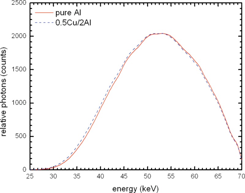
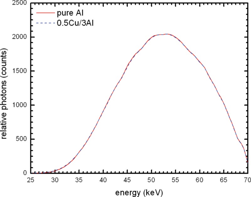
Figure 13 compares the spectrum for 21 mm pure Al to that for Cu/Al combination; there is a large difference in the height of the beam spectra. Using the 0.5 mm Cu and 2 mm Al filter combination there are over two times more photons. Figures 1415 show the spectra for different Cu/Al filters normalized to the output of pure Al. It can be seen that there is a left shift with 2 mm Al and with 3 mm Al the spectra are nearly identical. The HVL values in Table 4 show that 2.5 mm Al with 0.5 mm Cu would have essentially the same HVL as 21 mm pure Al.
Figure 13.
Simulated beam spectrum comparison of 0.5 mm Cu and 2.0 mm alloy 1100 and 21 mm 100% Al at .
Figure 14.
Simulated beam spectrum comparison of 0.5 mm Cu and 2.0 mm alloy 1100 and 21 mm 100% Al at normalized to the 100% Al spectrum to allow for better visualization of the differences.
Figure 15.
Simulated beam spectrum comparison of 0.5 mm Cu and 3.0 mm alloy 1100 and 21 mm 100% Al at normalized to the 100% Al spectrum to allow for better visualization of the differences.
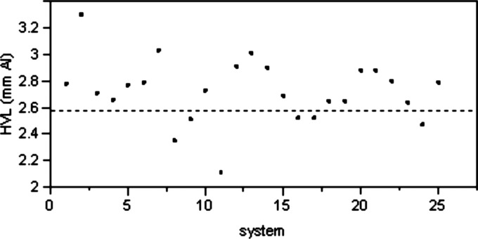
In addition to the investigation by the authors, several Task Group 116 members performed testing of x-ray systems at their institutions to determine if the target HVL of 6.8 mm Al can be achieved using 0.5 mm Cu filter in combination with an Al filter ranging in thickness from 0 to 4 mm. A total of 25 systems were tested. The initial filtration was measured for all 25 systems and the results are plotted in Fig. 16. It is important to note that out of the 25 systems only 6 had initial HVL of less than the maximum of 2.58 mm Al specified in IEC 61267.
Figure 16.
Initial X-ray system HVL on 25 tested units at .
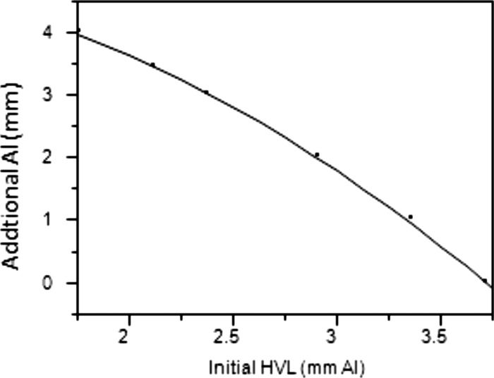
Since it is usually difficult to remove filtration in a clinical setting, it is much more practical to adjust the added filtration to reach the target HVL of 6.8 mm Al. The AAPM recommendation of varying the amount of Al in the Cu/Al filter combination is an appropriate method. Figure 17 plots the amount of additional Al needed to achieve the target HVL of 6.8 mm for different initial HVL values.
Figure 17.
Approximate Al to add to 0.5 mm Cu for RQA5@. Averaged from 25 systems tested.
Conclusion
We conclude that the IEC 61267 requirement to use 99.9% pure Al is unrealistic and is unnecessary. While the use of 21 mm of alloy 1100 Al is a close substitute, a slightly thinner filter would be appropriate to achieve the target HVL of 6.8 mm Al.
The use of a Cu/Al combination filter is an adequate alternative. Our simulation results show that 0.5 mm Cu and 3.0 mm Al provide the same HVL as 21 mm of pure Al. A side benefit of using Cu/Al combination is that it requires half of the exposure to achieve the same exposure as a 21 mm pure Al filter.
References
- Freedman M., Pe E., Mun S. K., Lo S. C. B., and Nelson M., “The potential for unnecessary patient exposure from the use of storage phosphor imaging systems,” Proc. SPIE 1897, 472–479 (1993). 10.1117/12.146998 [DOI] [Google Scholar]
- Gur D., Fuhman C. R., Feist J. H., Slifko R., and Peace B., “Natural migration to a higher dose in CR imaging,” Proceedings of the Eighth European Congress of Radiology (ISBN: 0938-7994), Vienna, Italy, 12–17 September 1993, p. 154.
- Seibert J. A., Shelton D. K., and Moore E. H., “Computed radiography x-ray exposure trends,” Acad. Radiol. 3(4), 313–318 (1996). 10.1016/S1076-6332(96)80247-9 [DOI] [PubMed] [Google Scholar]
- Van Metter R. and Yorkston J., “Applying a proposed definition for receptor dose to digital projection images,” Proc. SPIE 6142, 426–444 (2006. [Google Scholar]
- Huda W., “The current concept of speed should not be used to describe digital imaging systems,” Radiology 234, 345–346 (2005). 10.1148/radiol.2342040760 [DOI] [PubMed] [Google Scholar]
- International Organization for Standardization 9236-1:2004, 2004.
- Willis C. E. and Slovis T. L., “The ALARA concept in pediatric CR and DR: Dose reduction in pediatric radiographic exams—A white paper conference executive summary,” Pediatr. Radiol. 34,S162–S164 (2004). 10.1007/s00247-004-1264-y [DOI] [PubMed] [Google Scholar]
- Digital Imaging Communications in Medicine (DICOM) 3.0, Performance Standard (PS) 3.14, Grayscale Standard Display Function, National Electrical Manufacturers Association, 1300 N. 17th Street Rosslyn, VAa 22209, 2007.
- Digital Imaging Communications in Medicine (DICOM) 3.0, Supplement 111: Segmentation Storage SOP Class, National Electrical Manufacturers Association, 1300 N. 17th Street Rosslyn, VA 22209, 2007.
- Digital Imaging Communications in Medicine (DICOM) 3.0, Supplement 33: Grayscale Softcopy Presentation State Storage, National Electrical Manufacturers Association, 1300 N. 17th Street Rosslyn, VA 22209, 2007.
- Digital Imaging Communications in Medicine (DICOM) 3.0, Performance Standard (PS) 3.10, Media Storage and File Format for Media Interchange, National Electrical Manufacturers Association, 1300 N. 17th Street Rosslyn, VA 22209, 2007.
- IEC 61267 (ed. 2.0), Medical diagnostic X-ray equipment - Radiation conditions for use in the determination of characteristics, International Electrotechnical Commission (2005).
- IEC 62220-1 (ed. 1.0), Medical electrical equipment - characteristics of digital X-ray imaging devices - Part 1: Determination of the detective quantum efficiency, International Electrotechnical Commission (2003).
- Samei E., Seibert J. A., Willis C., Flynn M., Mah E., and Junck K., “Performance evaluation of computed radiography systems,” Med. Phys. 28, 361–371 (2001). 10.1118/1.1350586 [DOI] [PubMed] [Google Scholar]
- Seibert J. A., Bogucki T., Ciona T., Huda W., Karellas A., Mercier J., Samei E., Shepard S. J., Stewart B., Strauss K., Suleiman O., Tucker D., Uzenoff R., Weiser J., and Willis C., AAPM Report No. 93, American Association of Physicists in Medicine, College Park, MD (2006).
- Van Metter R. and Yorkston J., “Toward a universal definition of speed for digitally acquired projection images,” Proc. SPIE 5745, 442–457 (2005). 10.1117/12.595606 [DOI] [Google Scholar]
- Samei E.et al. , AAPM Report No. OR-3, American Association of Physicists in Medicine, College Park, MD (2005).
- Hendee W. R. and Rossi R. P., Quality assurance for radiographic x-ray units and associated equipment, DHEW Publication (OSTI ID 5545617), Bureau of Radiological Health, Rockville, MD, Colorado Univ. Medical Center, Denver, CO, FDA-79-8094 (1979).
- Christodoulou E. G., Goodsitt M. M., Chan H. P., and Hepburn T. W., “Phototimer setup for CR imaging,” Med. Phys. 27, 2652–2658 (2000). 10.1118/1.1319522 [DOI] [PubMed] [Google Scholar]
- Goldman L. W., “Speed values, AEC performance evaluation and quality control with digital receptors,” in Specifications, Performance Evaluations, and Quality Assurance for Radiographic and Fluoroscopic Equipment in the Digital Era, AAPM Medical Physics Monograph No. 30 edited by Goldman L. W. and Yester M. V., Medical Physics Publishing, Madison, WI: (2004). [Google Scholar]
- Wilkinson L. E. and Heggie J. C. P., “Determination of Correct AEC Function with Computed Radiography Cassettes,” Australas. Phys. Eng. Sci. Med. 20, 186–191 (1997). [PubMed] [Google Scholar]
- Willis C. E., Weiser J. C., Leckie R. G., Romlein J., and Norton G., “Optimization and quality control of computed radiography,” Proc. SPIE 2164, 178–185 (1994). 10.1117/12.173999 [DOI] [Google Scholar]
- Willis C. E., Leckie R. G., Carter J., Williamson M. P., Scotti S. D., and Norton G., “Objective measures of quality assurance in a computed radiography-based radiology department,” Proc. SPIE 2432, 588–599 (1995). 10.1117/12.208381 [DOI] [Google Scholar]
- Chotas H. G. and Ravin C. E., “Digital radiography with photostimulable storage phosphors: Control of detector latitude in chest imaging,” Invest. Radiol. 27, 822–828 (1992). 10.1097/00004424-199210000-00012 [DOI] [PubMed] [Google Scholar]
- Arreola M. and Rill L., “Management of pediatric radiation dose using Canon digital radiography,” Pediatr. Radiol. 34, S221–S226 (2004). 10.1007/s00247-004-1273-x [DOI] [PubMed] [Google Scholar]
- Hubbell J. H., NBS Report No. 29, 1969. (unpublished).
- Storm E., “Calculated bremsstrahlung spectra from thick tungsten targets,” Phys. Rev. A 5(6), pp. 2328–2338 (1978). 10.1103/PhysRevA.5.2328 [DOI] [Google Scholar]
- Storm E., “Emission of characteristic L and K radiation from thick tungsten targets,” J. Appl. Phys. 43(6), 2790–2796 (1972). 10.1063/1.1661596 [DOI] [Google Scholar]
- Fewell T. R. and Shuping R. E., “Handbook of mammography spectra,” DHEW Publication, FDA 79-8071, Bureau of Radiological Health, Rockville, MD (1978).
- Biggs F. and Lighthill R., Analytical Approximations for X-Ray Cross Sections II, SC-RR-71-0507, Weapons Effects Research Department, Sandia Laboratories, Albuquerque, New Mexico (1971).
- McMaster W. H., Del Grande N. Kerr, Mallett J. H., and Hubbell J. H., Compilation of x-ray cross sections UCRL-50174, sections I, II revision 1, III, IV, Atomic Data and Nuclear Data Tables, Volume 8, Issues 4–6, US Atomic Energy Commission (1970).
- Bureau of Mines, Mineral Facts and Problems (1985 edition), Bulletin #675, US Department of the Interior, Washington, DC (1986).
- Boone J. M. and Seibert J. A., “An accurate method for computer-generating tungsten anode x-ray spectra from 30 to 140 kV,” Med. Phys. 24, 1661–1670 (1997). 10.1118/1.597953 [DOI] [PubMed] [Google Scholar]
- Cullen D. E., Chen M. H., Hubbell J. H., Perkins S. T., Plechaty E. F., A. R. J., and Scofield J. H., Lawrence Livermore National Laboratory Report No. UCRL-50400, 1989. (unpublished).
- Hubbell J. H. and Seltzer S. M., Tables of X-Ray Mass Attenuation Coefficients and Mass Energy-Absorption Coefficients (Version 1.4), National Institute of Standards and Technology, Gaithersburg, MD (2004) (http://physics.nist.gov/xaamdi).


