

Abstract
To better engineer small-diameter blood vessels, a few types of novel scaffolds were fabricated from biodegradable poly(L-lactic acid) (PLLA) by means of thermally induced phase separation (TIPS) techniques. By utilizing the differences in thermal conductivities of the mold materials, the scaffolds with oriented gradient microtubular structures in axial or radial direction were created using benzene as the solvent. The porosity, tubular size, and the orientation direction of the microtubules can be controlled by polymer concentration, TIPS temperature, and materials of different thermal conductivities. The gradient microtubular structure was intended to facilitate cell seeding and mass transfer for cell growth and function. We also developed nanofibrous scaffolds with oriented and interconnected micro-tubular pore network by a one-step TIPS method using benzene/tetrahydrofuran mixture as the solvent without using porogen materials. The structural features of such scaffolds can be conveniently adjusted by varying the solvent ratio, phase separation temperature and polymer concentration to mimic the nanofibrous feature of extracellular matrix. These scaffolds were fabricated for the tissue engineering of small-diameter blood vessels by utilizing their advantageous structural features to facilitate blood vessel regeneration.
Keywords: blood vessel scaffold, PLLA, thermally induced phase separation, orientation, nanofiber
1. Introduction
Cardiovascular disease is still the leading cause of mortality in the United States, with 1 million lives lost each year and healthcare-related costs exceeding 300 billion dollars [1]. Large-diameter (inner diameter>6 mm) blood vessels have been successfully replaced with nondegradable polymeric materials such as Dacron (polyethylene terephthalate, PET) and expanded polytetrafluoroethylene (ePTFE). However, Dacron and PTFE are not the ideal solution for blood vessels because they are not natural tissues. For small-diameter (inner diameter<6 mm) blood vessels (SDBV), poor patency due to thrombosis and hyperplasia is a major problem when Dacron and PTFE are used. Tissue-engineered living blood vessels could potentially serve as a better source of grafts for patients [2–4]. Scaffolds play a pivotal role in tissue engineering [5–11]. Since Shinoka, Ma, and colleagues reported the feasibility of constructing heart valve leaflets and blood vessels using synthetic biodegradable polymer scaffolds [12–15], there have been very active research on vascular tissue engineering [16–31]. By using a synthetic biodegradable polymer scaffolding, it has been demonstrated that tissue engineered blood vessel substitutes could achieve adequate mechanical strength for arterial implantation either directly [13] or after in vitro pre-cultivation [30].
The structural design of the biodegradable synthetic matrices or scaffolds is a key issue in engineering living vascular substitutes, especially for SDBVs. To fabricate the blood vessel scaffolds, several factors should be considered: (1) biocompatibility and biodegradability of the polymers, (2) a high porosity with a structure suitable for cell seeding, distribution, function and tissue regeneration, (3) structural similarity to the native extracellular matrix (ECM) -- such as the tubular geometry at a macroscopic level and the fibrous architecture at the nanometer scale, and (4) adequate mechanical properties to support tissue regeneration. Although there are many ongoing efforts to develop scaffolds for blood vessel tissue engineering, the scaffolds developed up to this time point have various drawbacks and limitations. Yang fabricated scaffolds for SDBV tissue engineering using biodegradable polymers [32]. However, the micropores in such scaffolds were randomly oriented and with non-fibrous walls, having low structural similarity to blood vessels. Our lab developed the directional thermally induced phase separation (TIPS) technique to fabricate biodegradable polymer scaffolds consisting of an oriented array of open microtubules [33]. Wang and colleagues [34] prepared poly(lactic-co-glycolic acid) (PLGA) blood vessel scaffolds by adopting this method to achieve an axially orientated pore structure in the tubular walls. However, these scaffolds had solid walls without nanofibrous structure and had very low degree of lateral interconnectivity. Vaz [35] developed a bi-layered tubular scaffold composed of a stiff and oriented PLA outer shell and a random PCL fibrous inner layer (PLA/PCL) using the electrospinning technique. A major limitation of such a scaffold was that the pores were too small to allow uniform cell seeding and cultivation. Our laboratory developed a phase separation technique to fabricate synthetic nanofibrous matrices [36] as well as techniques to generate interconnected spherical pores within the polymer scaffolds [33, 37, 38]. However, they have not been previously used for the fabrication of tubular scaffolds with oriented pores to facilitate blood vessel tissue engineering.
In this work, we aimed to develop novel scaffolds with structural features on multiple scales to mimic certain key structural features of the extracellular matrix (ECM) and with designed pores/channels to facilitate cell seeding and the three-dimensional blood vessel regeneration.
2. Results
2.1. Architecture
When the temperature of a polymer solution is reduced below the freezing point of the solvent, solid-liquid phase separation occurs and a porous scaffold can be obtained after the removal of the solidified solvent [11]. When a typical mold such as a Teflon vial is used, random pores are generated as previously reported [11]. These randomly arranged pores are not ideal for uniform cell seeding, subsequent proliferation and organized blood vessel regeneration. In the present work, different parts of the molds are made of different materials (e.g., more thermally conductive steel and less conductive Teflon) so that the different thermal conductivities of these materials are utilized to regulate the phase separation process (Figure 1). When such a mold is cooled, the polymer solution inside phase separates under a directionally distributed temperature field because of the different thermal conductivities of the materials. For example, the steel parts reach lower temperatures (such as the freezing point of the solvent) more rapidly than the Teflon parts. Thus, temperature gradients are formed in the mold, leading to directional phase separation and the formation of oriented structures. Detailed structural features and the physical properties are discussed below.
Figure 1.

View of the molds for preparing the oriented gradient microtubule-structured scaffolds: (left) schematic illustrations of the molds; (top right) appearance of the molds with two different materials; (bottom right) appearance of produced scaffolds.
2.1.1. Microtubular gradient structure
Axial oriented structure
When a polymer solution was placed in a mold consisting of a steel bottom and Teflon wall/shaft/top, a temperature gradient was formed from bottom to top (from low to high) and maintained uniaxially during the thermally induced phase separation process. The characteristic architecture of an array of parallel microtubules was achieved (Figure 2). When benzene was used as the solvent of poly(L-lactic acid) (PLLA), the cross-sections of the microtubules were polygons with 3–7 sides. When the polymer concentration was increased from 2.5% to 10%, the porosity of the formed scaffolds was slightly reduced from 95% to 90%, and the average pore size was also decreased from 120–150μm to 80–120μm. When phase separation temperature was decreased from −20°C to −196°C (liquid nitrogen), the pore size was greatly decreased from 115–140μm to 20–40μm (Table 1).
Figure 2.

SEM micrographs of cross section under axial temperature gradient at −20°C for PLLA/benzene solutions with different concentrations (wt/v): (A) 2.5%; (B) 5.0%; (C) 7.5%; (D) 10.0%; (E) longitudinal section, 7.5%; (F) illustration of the microtubular structure (inset – cross-section).
Table 1.
Structural and mechanical properties of the solid-walled PLLA scaffolds
| Polymer | Solvent | Concentration (wt/v, %) | Phase separation temperature (°C) | Pore structure | Density (g/cm3) | Porosity (%) | Pore Size (μm) | Compressive modulus (MPa) | Compressive yield strength (MPa) | ||
|---|---|---|---|---|---|---|---|---|---|---|---|
|
| |||||||||||
| axial | radial | axial | radial | ||||||||
|
| |||||||||||
| PLLA | Benzene | 2.5 | −20 | ◀ | 0.064 | 94.9 | 0–200 | — | — | — | — |
| PLLA | Benzene | 2.5 | −20 | ▶ | 0.063 | 95.0 | 0–210 | — | — | — | — |
| PLLA | Benzene | 2.5 | −20 | ▲ | 0.065 | 94.8 | 120–150 | 0.55 | 0.32 | 0.22 | 0.13 |
| PLLA | Benzene | 5.0 | −20 | ◀ | 0.098 | 92.2 | 0–150 | 1.7 | 4.9 | 0.16 | 0.40 |
| PLLA | Benzene | 5.0 | LN | ◀ | 0.096 | 92.4 | 10–20 | 2.1 | 5.2 | 0.20 | 0.45 |
| PLLA | Benzene | 5.0 | −20 | ▶ | 0.097 | 92.3 | 0–155 | 1.8 | 4.5 | 0.17 | 0.43 |
| PLLA | Benzene | 5.0 | LN | ▶ | 0.094 | 92.5 | 10–20 | 2.0 | 5.0 | 0.21 | 0.48 |
| PLLA | Benzene | 5.0 | −20 | ▲ | 0.102 | 91.9 | 115–140 | 3.8 | 2.0 | 0.38 | 0.15 |
| PLLA | Benzene | 5.0 | LN | ▲ | 0.101 | 92.0 | 20–40 | 4.2 | 2.9 | 0.43 | 0.23 |
| PLLA | Benzene | 7.5 | −20 | ◀ | 0.123 | 90.2 | 0–120 | 2.6 | 6.3 | 0.27 | 0.53 |
| PLLA | Benzene | 7.5 | −20 | ▶ | 0.125 | 90.1 | 0–120 | 2.5 | 5.9 | 0.24 | 0.56 |
| PLLA | Benzene | 7.5 | −20 | ▲ | 0.125 | 90.1 | 90–130 | 4.5 | 2.8 | 0.44 | 0.21 |
| PLLA | Benzene | 10.0 | −20 | ◀ | 0.133 | 89.4 | 0–100 | 3.6 | 8.4 | 0.37 | 0.85 |
| PLLA | Benzene | 10.0 | −20 | ▶ | 0.135 | 89.3 | 0–100 | 3.9 | 8.7 | 0.40 | 0.88 |
| PLLA | Benzene | 10.0 | −20 | ▲ | 0.131 | 89.6 | 80–120 | 7.7 | 4.0 | 0.68 | 0.34 |
◀:O/I oriented structure; ▶: I/O oriented structure; ▲: bottom-top oriented structure
Radially oriented gradient structure
When the mold was composed of a steel wall and Teflon bottom/top/shaft or a reversed composition (steel shaft/bottom/top and a Teflon wall), a temperature gradient was formed in the radial direction either from outside (warmer) to inside (colder) or from inside (warmer) to outside (colder). Accordingly, the radially oriented gradient pore structures of the PLLA scaffolds were formed (Figures 3–5). They were named O/I (microtube size decreased gradually from outside wall to inside wall) and I/O (microtube size decreased gradually from inside wall to outside wall) structures in the following discussion.
Figure 3.

SEM micrographs of cross sections of vessel scaffold prepared under radial temperature gradient (I/O structure) at −20°C for PLLA/benzene solutions with different concentrations (wt/v): (A) 2.5%; (B) 5.0%; (C) 7.5%; (D) 10.0%.
Figure 5.
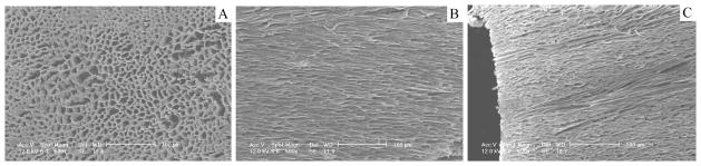
SEM micrographs of axially oriented gradient structure of scaffolds prepared using 5.0% (wt/v) PLLA/Benzene solution at −196°C: (A) cross section; (B) cross section, O/I structure; (C) cross section, I/O structure.
It was found that the resulting scaffolds had an oriented fishbone-like architecture, which had parallel microtubes with thin partitions. Also, the microtube diameters became radially larger or smaller along the direction of the temperature gradient (summarized in Figure 6). For instance, the microtube size of the I/O structured gradient scaffold was gradually reduced from 200 μm to nearly zero while that of the O/I structured scaffold was gradually increased from about 30 to 200 μm. The microtube size was reduced with increasing polymer concentration (Figures 2–5 and Table 1). The radial temperature gradient direction did not significantly affect the average pore size at the same polymer concentration. The pore size formed under the radial temperature gradient was also greatly reduced from 200μm to 20μm when the temperature changed from −20°C to −196°C (Figures 3–5 and Table 1). The phase separation temperature had no obvious effect on the porosity (Table 1). It is worth noting that there was no obvious gradient microtubule structure and no fishbone-like structure under the phase separation temperature of −196°C (Figure 5).
Figure 6.

Pore size of the radially oriented gradient microtubular structure. (PLLA/benzene solutions with PLLA concentration of 5.0%, phase separation temperature: −20°C)
The phase separation temperature and the direction of temperature gradient both had clear effects on the micro-architecture of the PLLA scaffolds. This was due to the nature of the solid-liquid phase separation, i.e., the crystallization of the solvent, which controls the pore architecture of the formed scaffold [33]. Different directions of the temperature gradient resulted in different crystallization paths of the solvent (benzene). In comparison with the axial temperature gradient, benzene has a shorter crystallization path under the radial temperature gradient due to its thinner wall thickness. Therefore, benzene rapidly crystallized under such an extremely low temperature and there likely was not enough time to form the gradient and branched pore structure.
2.1.2. Nanofibrous interconnected structure
It has been shown in our previous studies that the nano-fibrous architecture advantageously enhances bone and cartilage tissue regeneration [37, 39–43]. The native blood vessels are largely composed of collagens Type I and III and elastin, which are fibers of the nano-meter dimensions. Therefore, the scaffold to engineer a blood vessel may be advantageous if it mimics the nano-sized fiber architecture.
Although the scaffolds resulting from PLLA/benzene solutions are partly similar to the natural blood vessels in structure, their solid pore walls are greatly different from the blood vessels composed of nanofibrous proteins. In the following work of this paper, a benzene/tetrahydrofuran (THF) mixture was used as the solvent for PLLA in the TIPS procedure to create a nanofibrous scaffold with oriented and interconnected microtubules (Figure 7). When the solvent was THF alone, the scaffold was composed of nanofibers, but few micro-sized pores (Figure 7J&K). However, when benzene and THF were mixed at various ratios, nano-fibrous matrices with oriented microtubules on the micrometer scale were created. Similar to the scaffold made from PLLA/benzene solution (in section 2.1.1), these scaffolds had low densities and high porosities. The density increased and the porosity decreased with increasing polymer concentration. When benzene/THF ratio was 9/1 (v/v), the diameter of the microtubule was from about 80 μm to 250 μm. A partly nanofibrous structure was formed in these microtubule walls and the average diameter of the nanofibers was 165±15 nm. When the ratio of benzene/THF was 8:2 (v/v) and 6:4 (v/v), complete nanofibrous structure was achieved. The average fiber diameter of the fibrous matrices did not change statistically with the concentration of the polymer or the ratio of benzene/THF. The fiber diameter was similar to what was seen in nano-fibrous PLLA matrices fabricated using THF alone. However, the size of microtubules was greatly reduced with further increase of THF percentage in the solvent mixture.
Figure 7.

SEM micrographs of PLLA scaffolds prepared using PLLA solutions in benzene and THF using a TIPS technique. A–C: 7.5% (wt/v) PLLA/(benzene/THF), benzene/THF (v/v)=9:1; D–F: 7.5% (wt/v) PLLA/(benzene/THF), benzene/THF (v/v)=8:2; G–I: 7.5% (wt/v) PLLA/(benzene/THF), benzene/THF (v/v)=6:4; J–K: 7.5% (wt/v) PLLA/(benzene/THF), benzene/THF (v/v)=0:10. The TIPS temperature was −20°C.
At the same benzene/THF ratio, the pore size decreased with decreasing temperature (Table 2) and increasing polymer concentration (Figure 8 and Table 2), although the diameter of the nanofibers did not change appreciably with the temperature (Figure 9 and Table 2). It is important to note that in the benzene/THF ratio range studied, the microtubules with nanofibrous walls were highly interconnected “tunnels” in the scaffolds, and the “tunnels” were also oriented in the orthogonal directions. Table 2 summarized the structural properties of the matrices described here.
Table 2.
Structural and mechanical properties of the nanofibrous PLLA scaffolds
| Polymer | Solvent (Benzene/THF) | Concentration (wt/v %) | Phase separation temperature (°C) | Density (g/cm3) | Porosity (%) | Pore Size (μm) | Fiber Diameter (nm) | Compressive modulus (MPa) | Compressive yield strength (MPa) |
|---|---|---|---|---|---|---|---|---|---|
| PLLA | 100/0 | 7.5 | −20 | 0.125 | 90.1 | 120±16 | — | 4.5 | 0.44 |
| PLLA | 90/10 | 7.5 | −20 | 0.102 | 91.9 | 107±15 | 165±15 | 4.2 | 0.41 |
| PLLA | 80/20 | 2.5 | −20 | 0.048 | 96.2 | 153±25 | 158±20 | 0.5 | 0.18 |
| PLLA | 80/20 | 5.0 | −20 | 0.065 | 94.8 | 126±18 | 155±18 | 2.9 | 0.30 |
| PLLA | 80/20 | 7.5 | −20 | 0.093 | 92.6 | 80±7 | 157±21 | 3.5 | 0.38 |
| PLLA | 80/20 | 10.0 | −20 | 0.110 | 91.3 | 77±9 | 160±31 | 6.4 | 0.52 |
| PLLA | 80/20 | 5.0 | −80 | 0.069 | 94.5 | 115±20 | 158±20 | 3.2 | 0.33 |
| PLLA | 80/20 | 5.0 | LN | 0.068 | 94.6 | 52±12 | 154±23 | 3.3 | 0.32 |
| PLLA | 60:40 | 7.5 | −20 | 0.091 | 92.8 | 20±3 | 143±20 | 3.0 | 0.28 |
| PLLA | 0/100 | 7.5 | −20 | 0.094 | 92.5 | — | 144±22 | 3.0 | 0.38 |
Figure 8.

SEM micrographs of PLLA scaffolds prepared with various polymer concentrations using a TIPS technique (Benzene/THF=8:2, PLLA concentration (wt/v): A, 2.5%; B: 5.0%; C: 7.5%; D: 10.0%, the TIPS temperature was −20°C).
Figure 9.

SEM micrographs vs. the TIPS temperature (Benzene/THF=8:2, the PLLA concentration is 5.0% (wt/v). A: −20°C; B: −80°C; C: −196°C).
Compared with the simple solid-liquid phase separation of PLLA/benzene solution, there are likely two stages of phase separation of the PLLA/(benzene/THF) solution in the scaffold fabrication process: solid-liquid phase separation followed by a liquid-liquid phase separation. Benzene has a much higher freezing temperature than THF. Therefore, during the first stage of the solid-liquid phase separation, the crystallization of benzene created micropores. The oriented gradient microtubular structure in an axial or radial direction (similar to Figures 2–5) can be achieved during this step if a proper temperature gradient was utilized. After this stage, the polymer solution was separated into a solidified benzene phase and a polymer-rich PLLA/THF phase, which was partially compartmented by the benzene crystals. The nano-fibrous structure was formed during the second stage by spinodal liquid–liquid phase separation and subsequent crystallization of the polymer-rich phase. Figure 10 describes the proposed phase separation mechanism of PLLA/(benzene/THF) solutions.
Figure 10.

Schematic illustration of the nanofibrous scaffolds with interconnected microtubular structure in a TIPS process of PLLA/Benzene/THF solutions.
2.2. Mechanical properties
The mechanical properties, including compressive modulus and compressive yield strength, are shown in Tables 1 and 2. The typical results on the compressive yield strength are presented in Figures 11&12. For the scaffolds possessing oriented gradient microtubules, the anisotropic architecture led to anisotropic mechanical properties. Both the compressive modulus and the yield strength of a scaffold with a microtubular architecture were significantly greater in the longitudinal direction than in the transverse direction of the tubular structure (Table 1 & Figure 11). Both the compressive modulus and the compressive yield strength increased with polymer concentration as expected (Tables 1&2 and Figure 11). At the same polymer concentration, there was no statistical difference in the mechanical properties between the two types of radially oriented gradient (O/I or I/O) scaffolds (Table 1 and Figure 11).
Figure 11.

Compressive yield strength of PLLA scaffolds prepared with benzene as the solvent using a TIPS technique. The PLLA concentration was 5.0%. The TIPS temperature was −20°C.
Figure 12.

Compressive yield strength of PLLA scaffolds prepared with PLLA solutions in benzene, THF, and their mixtures using a TIPS technique. The TIPS temperature was −20°C.
Compressive modulus and compressive yield strength of the nano-fibrous scaffolds with interconnected channels were both slightly lower than those of the scaffolds with a solid-walled oriented gradient structure at the same polymer concentration in the oriented direction of microtubules. At similar polymer concentrations, the scaffolds with a solid-walled structure (prepared using benzene) had larger average pore size and higher skeletal density of the pore walls, which may have led to the higher compressive modulus and yield strength. The average pore size became smaller as the THF was introduced and increased, resulting in the looser aggregation of nanofibers in the pore walls, which might be associated with the lower compressive modulus and yield strength.
2.3. Cellular migration into the scaffolds in vivo
To investigate cell migration into and distribution within the scaffolds of different pore structures in vivo, scaffolds with radially oriented and non-oriented pores were subcutaneously implanted into mice. After 2 weeks of implantation, H-E staining of the cross sections of implants showed that abundant host cells migrated into the scaffolds with orientated pores and the fibroblast-like cells appeared healthy in the micro-channels (Figure 13A). In contrast, substantially fewer cells migrated into the scaffolds with non-oriented pores (Figure 13B). Both hypes of the scaffolds maintained geometrical shape and structural integrity during the 2-week implantation.
Figure 13.

After 2 weeks of implantation, H–E staining of the cross sections of implants showed that abundant host cells migrated into the scaffolds with orientated pores and the fibroblast-like cells appeared healthy in the micro-channels (Figure 13A), substantially fewer cells migrated into the scaffolds with non-oriented pores (Figure 13B). Both hypes of the scaffolds maintained their original shapes. Scale bar: 200 μm.
3. Discussion
It is well recognized that scaffolds play a critical role in tissue engineering. The three-dimensional pore structure and surface morphology of the scaffolds affect the quality of the tissue being developed on the scaffold. However, there are limited reports on the scaffolds for blood vessel engineering. Blood vessels as many other tissues including nerve, muscle, tendon, ligament, bone and teeth, have oriented architectures.
In this paper, biodegradable PLLA scaffolds with an oriented microtubular structure along different directions were successfully created. We have demonstrated how to control the architectural parameters such as porosity, tubular diameter, and orientation direction of the microtubules by varying processing parameters such as polymer concentration and temperature gradient. Moreover, by designing the molds using different materials for different parts, we can create various oriented microtubules and gradient pore structures. For instance, a gradient scaffold can be created with the oriented structure from the outside wall (with larger pores) to the inside wall (with smaller pores). The inside layer with smaller pores could be advantageous for the seeding and growth of endothelial cells (ECs), while the outside layer with the bigger pores could create a more suitable environment for the growth of smooth muscle cells (SMCs) and their matrix synthesis. It is also likely that the radially oriented microtubules with in a scaffold provide an easier pathway for cell seeding and the uniform distribution throughout the scaffold. The scaffold implantation study in this paper has demonstrated that cells can easily migrate into radially oriented tubular pores to achieve higher cell density and more uniform cell distribution throughout the scaffold than into the random pores of the control scaffold. The healthy appearance of the cells in the radially oriented pores may be associated with the better mass transfer conditions than in less inter-connected pores of the control scaffold. The intact vessel-shaped geometry also demonstrates the adequate mechanical properties to support tissue regeneration in the ectopic implantation model used in this study. Although beyond the scope of this work, future studies are warranted to investigate the effects and mechanisms of pore structure and orientation on cell function such as proliferation, differentiation and neo tissue development along with the degradation of the polymer scaffolds in a blood vessel replacement model.
Inspired by the nanofibrous architecture of collagen in natural ECM, our laboratory previously developed synthetic nanofibrous polymer scaffolds with macro-/micro- pores by combining porogen template-leaching and phase separation techniques [6, 38, 44]. In the present work, we developed a technique to fabricate the scaffolds with both the interconnected microtubular pores and the nanofibrous pore wall architecture without using any templates (preformed porogen materials). By simply controlling the ratio of benzene/THF, the polymer concentration and the phase separation temperature, scaffolds with different porosity, microtubule size, nanofiber density on the microtubule walls can be created, allowing for the optimization of scaffolds for specific cells and specific tissues. Different from the non-directional spherical pore structure of the scaffolds generated by paraffin or sugar spheres, both oriented and interconnected microtubular network can be achieved in the scaffolds using the new methods developed in this work. The new fabrication technique is simple, tunable, and can also greatly shorten the production time of the scaffolds. Moreover, the technique is versatile and likely has the general applicability to other polymers as the mold design and the solvent type rather than the polymer type play the main roles in determining the gradient microtubular and nanofibrous architectures.
4. Conclusions
This paper presented a few types of novel scaffolds fabricated from biodegradable polymers by means of new thermally induced phase separation techniques. Tubular biodegradable PLLA scaffolds were fabricated for the tissue engineering of small-diameter blood vessels by utilizing their certain nano-structural similarities to the ECM and advantageous pore design to facilitate tissue regeneration. We demonstrated how to control the architectural parameters such as porosity, pore size, and the orientation direction of the micro-tubular pores using the processing parameters, including polymer concentration and temperature gradient, especially utilizing the differences in thermal conductivity of the mold materials. The gradient microtubular structure was shown to facilitate cell migration and uniform distribution throughout the scaffold in vivo. The oriented gradient pores were also intended to improve mass transfer conditions for cell growth and function. We also developed nanofibrous scaffolds with oriented and interconnected micro-tubular pore network by a one-step TIPS method without use of any template materials. The structural features of such scaffolds can be conveniently adjusted by varying the solvent ratio, phase separation temperature and polymer concentration. The fabrication technology does not require expensive facilities, is easy to carry out, and can shorten the scaffold fabrication time. These fabrication technologies are versatile and could be utilized to fabricate scaffolds and complex porous materials from different polymers and for tissue engineering and various other applications.
5. Experimental
Materials
PLLA with an inherent viscosity of 1.4–1.8 dl/g was purchased from Boehringer Ingelheim (Ingelheim, Germany) and was used as received. Benzene, THF and other reagents were obtained from Aldrich Chemical Company (Milwaukee, WI). They were of analytical grade and used without further treatment.
Vessel scaffold fabrication
Three different molds were designed to fabricate different blood vessel scaffolds with orientation and gradient pore structures. The molds were composed of top and bottom plates, inner shaft and outer cylinder made of the same or different materials, as shown in Figure 1. The usage of different materials (metal and Teflon) was intended to create different temperature gradients for the TIPS process. In the present study, the molds with an inner-diameter of 3.00 mm and an outer-diameter of 5.00 mm were used.
The PLLA was dissolved in benzene to form homogeneous solutions with concentrations of 2.5%–10%. The polymer solution was poured into different molds then transferred into a freezer set to a chosen temperature to induce phase separation. The phase-separated polymer/solvent system was then transferred into a freeze drying vessel at −5 to −10°C in an ice/salt bath, and was freeze-dried under vacuum (pressure lower than 0.5 mmHg) for 72 hours. The dried scaffolds were then kept in a desiccator until characterization or usage.
For the preparation of nano-fibrous PLLA scaffolds, benzene and THF with various ratios were used as mixed solvents. After the phase separation, the molds containing the polymer solution were immersed into cold hexane for 2 days to extract the solvents, changing the hexane three times a day. Hexane was then exchanged with cyclohexane. The polymer scaffolds were removed from the cyclohexane, and was frozen at −70°C for at least 5 hours. The frozen scaffolds were lyophilized at −10°C for 72 hours and then kept in a desiccator until usage.
Structure/property characterization
To estimate the density and porosity of the PLLA scaffolds, the inner-diameter, outer-diameter and height of each scaffold were measured after freeze-drying to calculate the volume of each scaffold. The mass of each scaffold was measured with an analytical balance, and the overall density (Df) was calculated from the volume and the mass. The porosity ε of each scaffold was calculated from the measured overall density Df of the fibrous matrix and the skeletal density Dp using previously described techniques. Porosity was defined as:
Where the skeletal density Dp of the scaffolds was given by:
Where Xc was the degree of crystallinity determined with differential scanning calorimetry as described elsewhere [36]. For PLLA, Da=1.248g/mL (density of amorphous polymer) and Dc=1.290g/mL (density of 100% crystalline polymer).
Porous morphologies of the scaffolds were examined using scanning electron microscopy (SEM) (S-3200N, Hitachi, Japan). To expose the internal architecture, a sample was cut carefully with a razor blade after freeze-drying. All samples were coated with gold using a sputter coater (Desk-II, Denton Vacuum Inc., Moorstown, NJ), where the pressure was below 50 mTorr, the current was approximately 40 mA, and the coating time was 120 s. The diameters of the pores and the nanofibers were measured from SEM micrographs using Image-pro plus software (Media Cybernetics). More than 40 micropores and nanofibers were chosen to calculate an average diameter. To determine the gradient structure of the pores, each wall thickness was divided into ten equal parts from the inner-wall to the outer-wall or from outer-wall to inner-wall.
The compressive mechanical properties of PLLA scaffolds were measured with an MTS Synergie 200 mechanical tester (MTS Systems Corporation, Eden Prairie, MN). For compression testing, the specimens were homocentric tubes measuring 5 mm in outer-diameter, 3 mm in inner-diameter and 3.0 mm in height. The load was applied in the direction either parallel or perpendicular to the tubular axis. The crosshead speed was 0.5 mm/min and the compressive modulus was defined as the initial linear modulus. The yield strength was determined from the cross point of the two tangents on the stress-strain curve around the yield point. At least 5 specimens were tested for each sample.
Subcutaneous implantation
The animal procedures were performed according to the protocol approved by the University of Michigan Committee of Use and Care of Laboratory Animals. The tubular scaffolds (2 mm in thickness) were implanted into subcutaneous pockets of 6–8 weeks old C57BL/6 male mice (Charles River Laboratories, Wilmington, MA). Surgery was performed under general inhalation anesthesia with isofluorane. Two midsagittal incisions were made on the dorsa and one subcutaneous pocket was created on each side of each incision using blunt dissection. One scaffold was implanted subcutaneously into each pocket. Four samples were implanted for each group. After placement of implants, the incisions were closed with staples. At the end of 2 weeks of implantation period, the mice were euthanized and the implants were harvested.
Histological analysis
Implants were washed in PBS, fixed with 3.7% formaldehyde in PBS overnight, dehydrated through a graded series of ethanol, embedded in paraffin, and sectioned at a thickness of 5 μm. Sections were deparaffinized, rehydrated with a graded series of ethanol, and stained with hematoxylin and eosin (H–E).
Figure 4.

SEM micrographs of cross sections of vessel scaffolds under radial temperature gradient (O/I structure) at −20°C from PLLA/benzene solutions with different concentrations (wt/v): (A) 2.5%; (B) 5.0%; (C) 7.5%; (D) 10.0%.
Acknowledgments
The research was supported by the National Institutes of Health (NIDCR Research Grants DE015384 and DE017689: PXM).
References
- 1.Isenberg BC, Williams C, Tranquillo RT. Circulation Research. 2006;98:25–35. doi: 10.1161/01.RES.0000196867.12470.84. [DOI] [PubMed] [Google Scholar]
- 2.Nerem RM, Seliktar D. Annual Review of Biomedical Engineering. 2001;3:225–243. doi: 10.1146/annurev.bioeng.3.1.225. [DOI] [PubMed] [Google Scholar]
- 3.Germain L, Remy-Zolghadri M, Auger F. Medical & Biological Engineering & Computing. 2000;38:232–240. [PubMed] [Google Scholar]
- 4.Teebken OE, Haverich A. European Journal of Vascular and Endovascular Surgery. 2002;23:475–485. doi: 10.1053/ejvs.2002.1654. [DOI] [PubMed] [Google Scholar]
- 5.Ma PX. Adv Drug Deliv Rev. 2008;60:184–198. doi: 10.1016/j.addr.2007.08.041. [DOI] [PMC free article] [PubMed] [Google Scholar]
- 6.Wei GB, Ma PX. Advanced Functional Materials. 2008;18:3568–3582. doi: 10.1002/adfm.200800662. [DOI] [PMC free article] [PubMed] [Google Scholar]
- 7.Wang YQ, Noga DE, Yoon K, Wojtowicz AM, Lin ASP, Garcia AJ, Collard DM, Weck M. Advanced Functional Materials. 2008;18:3638–3644. [Google Scholar]
- 8.Zhang YJ, Wang SP, Eghtedari M, Motamedi M, Kotov NA. Advanced Functional Materials. 2005;15:725–731. [Google Scholar]
- 9.Boccaccini AR, Chicatun F, Cho J, Bretcanu O, Roether JA, Novak S, Chen Q. Advanced Functional Materials. 2007;17:2815–2822. [Google Scholar]
- 10.Xie BJ, Parkhill RL, Warren WL, Smay JE. Advanced Functional Materials. 2006;16:1685–1693. [Google Scholar]
- 11.Zhang R, Ma PX. J Biomed Mater Res. 1999;44:446–55. doi: 10.1002/(sici)1097-4636(19990315)44:4<446::aid-jbm11>3.0.co;2-f. [DOI] [PubMed] [Google Scholar]
- 12.Shinoka T, Ma PX, Shum-Tim D, Breuer CK, Cusick RA, Zund G, Langer R, Vacanti JP, Mayer JE., Jr Circulation. 1996;94:II164–8. [PubMed] [Google Scholar]
- 13.Shinoka T, Shum-Tim D, Ma PX, Tanel RE, Isogai N, Langer R, Vacanti JP, Mayer JE. Journal of Thoracic and Cardiovascular Surgery. 1998;115:536–545. doi: 10.1016/S0022-5223(98)70315-0. [DOI] [PubMed] [Google Scholar]
- 14.Shinoka T, Breuer CK, Tanel RE, Zund G, Miura T, Ma PX, Langer R, Vacanti JP, Mayer JE., Jr Ann Thorac Surg. 1995;60:S513–6. doi: 10.1016/0003-4975(95)00733-4. [DOI] [PubMed] [Google Scholar]
- 15.Breuer CK, Shinoka T, Zund G, Mooney DJ, Ma PX, Langer R, Mayer TE, Vacanti JP. Biotechnology and Bioengineering. 1996;50:562–567. doi: 10.1002/(SICI)1097-0290(19960605)50:5<562::AID-BIT11>3.0.CO;2-L. [DOI] [PubMed] [Google Scholar]
- 16.Stegemann JP, Kaszuba SN, Rowe SL. Tissue Engineering. 2007;13:2601–2613. doi: 10.1089/ten.2007.0196. [DOI] [PMC free article] [PubMed] [Google Scholar]
- 17.Sarraf CE, Harris AB, McCulloch AD, Eastwood M. Cell Proliferation. 2003;36:241–254. doi: 10.1046/j.1365-2184.2003.00281.x. [DOI] [PMC free article] [PubMed] [Google Scholar]
- 18.He HB, Matsuda T. Tissue Engineering. 2002;8:213–224. doi: 10.1089/107632702753724987. [DOI] [PubMed] [Google Scholar]
- 19.Boland ED, Matthews JA, Pawlowski KJ, Simpson DG, Wnek GE, Bowlin GL. Frontiers in Bioscience. 2004;9:1422–1432. doi: 10.2741/1313. [DOI] [PubMed] [Google Scholar]
- 20.Opitz F, Schenke-Layland K, Richter W, Martin DP, Degenkolbe I, Wahlers T, Stock UA. Annals of Biomedical Engineering. 2004;32:212–222. doi: 10.1023/b:abme.0000012741.85600.f1. [DOI] [PubMed] [Google Scholar]
- 21.Xu CY, Inai R, Kotaki M, Ramakrishna S. Tissue Engineering. 2004;10:1160–1168. doi: 10.1089/ten.2004.10.1160. [DOI] [PubMed] [Google Scholar]
- 22.Mironov V, Kasyanov V, Shu XZ, Eisenberg C, Eisenberg L, Gonda S, Trusk T, Markwald RR, Prestwich GD. Biomaterials. 2005;26:7628–7635. doi: 10.1016/j.biomaterials.2005.05.061. [DOI] [PubMed] [Google Scholar]
- 23.Engbers-Buijtenhuijs P, Buttafoco L, Poot AA, Dijkstra PJ, de Vos RAI, Sterk LMT, Geelkerken RH, Vermes I, Feijen J. Biomaterials. 2006;27:2390–2397. doi: 10.1016/j.biomaterials.2005.10.016. [DOI] [PubMed] [Google Scholar]
- 24.Sarkar S, Lee GY, Wong JY, Desai TA. Biomaterials. 2006;27:4775–4782. doi: 10.1016/j.biomaterials.2006.04.038. [DOI] [PubMed] [Google Scholar]
- 25.Stitzel J, Liu L, Lee SJ, Komura M, Berry J, Soker S, Lim G, Van Dyke M, Czerw R, Yoo JJ, Atala A. Biomaterials. 2006;27:1088–1094. doi: 10.1016/j.biomaterials.2005.07.048. [DOI] [PubMed] [Google Scholar]
- 26.Campbell GR, Campbell JH. Current Pharmaceutical Biotechnology. 2007;8:43–50. doi: 10.2174/138920107779941426. [DOI] [PubMed] [Google Scholar]
- 27.Couet F, Rajan N, Mantovani D. Macromolecular Bioscience. 2007;7:701–718. doi: 10.1002/mabi.200700002. [DOI] [PubMed] [Google Scholar]
- 28.Lovett M, Cannizzaro C, Daheron L, Messmer B, Vunjak-Novakovic G, Kaplan DL. Biomaterials. 2007;28:5271–5279. doi: 10.1016/j.biomaterials.2007.08.008. [DOI] [PMC free article] [PubMed] [Google Scholar]
- 29.Stankus JJ, Soletti L, Fujimoto K, Hong Y, Vorp DA, Wagner WR. Biomaterials. 2007;28:2738–2746. doi: 10.1016/j.biomaterials.2007.02.012. [DOI] [PMC free article] [PubMed] [Google Scholar]
- 30.Niklason LE, Gao J, Abbott WM, Hirschi KK, Houser S, Marini R, Langer R. Science. 1999;284:489–93. doi: 10.1126/science.284.5413.489. [DOI] [PubMed] [Google Scholar]
- 31.Zorlutuna P, Hasirci N, Hasirci V. Journal of Tissue Engineering and Regenerative Medicine. 2008;2:373–377. doi: 10.1002/term.99. [DOI] [PubMed] [Google Scholar]
- 32.Yang J, Motlagh D, Webb AR, Ameer GA. Tissue Engineering. 2005;11:1876–1886. doi: 10.1089/ten.2005.11.1876. [DOI] [PubMed] [Google Scholar]
- 33.Ma PX, Zhang RY. Journal of Biomedical Materials Research. 2001;56:469–477. doi: 10.1002/1097-4636(20010915)56:4<469::aid-jbm1118>3.0.co;2-h. [DOI] [PubMed] [Google Scholar]
- 34.Hu XX, Shen H, Yang F, Bei JZ, Wang SG. Biomaterials. 2008;29:3128–3136. doi: 10.1016/j.biomaterials.2008.04.010. [DOI] [PubMed] [Google Scholar]
- 35.Vaz CM, van Tuijl S, Bouten CVC, Baaijens FPT. Acta Biomaterialia. 2005;1:575–582. doi: 10.1016/j.actbio.2005.06.006. [DOI] [PubMed] [Google Scholar]
- 36.Ma PX, Zhang RY. Journal of Biomedical Materials Research. 1999;46:60–72. doi: 10.1002/(sici)1097-4636(199907)46:1<60::aid-jbm7>3.0.co;2-h. [DOI] [PubMed] [Google Scholar]
- 37.Chen VJ, Ma PX. Biomaterials. 2004;25:2065–2073. doi: 10.1016/j.biomaterials.2003.08.058. [DOI] [PubMed] [Google Scholar]
- 38.Wei GB, Ma PX. Journal of Biomedical Materials Research Part A. 2006;78A:306–315. doi: 10.1002/jbm.a.30704. [DOI] [PubMed] [Google Scholar]
- 39.Woo KM, Chen VJ, Ma PX. Journal of Biomedical Materials Research Part A. 2003;67A:531–537. doi: 10.1002/jbm.a.10098. [DOI] [PubMed] [Google Scholar]
- 40.Woo KM, Jun JH, Chen VJ, Seo JY, Baek JH, Ryoo HM, Kim GS, Somerman MJ, Ma PX. Biomaterials. 2007;28:335–343. doi: 10.1016/j.biomaterials.2006.06.013. [DOI] [PubMed] [Google Scholar]
- 41.Chen VJ, Smith LA, Ma PX. Biomaterials. 2006;27:3973–3979. doi: 10.1016/j.biomaterials.2006.02.043. [DOI] [PubMed] [Google Scholar]
- 42.Hu J, Feng K, Liu X, Ma PX. Biomaterials. 2009;30:5061–7. doi: 10.1016/j.biomaterials.2009.06.013. [DOI] [PMC free article] [PubMed] [Google Scholar]
- 43.Hu J, Liu X, Ma PX. Biomaterials. 2008;29:3815–3821. doi: 10.1016/j.biomaterials.2008.06.015. [DOI] [PMC free article] [PubMed] [Google Scholar]
- 44.Ma PX, Choi JW. Tissue Engineering. 2001;7:23–33. doi: 10.1089/107632701300003269. [DOI] [PubMed] [Google Scholar]