Abstract
A new, DMF-coordinated, pre-organized diiron compound [Fe2(N-Et-HPTB)(DMF)4](BF4)3 (1) was synthesized, avoiding the formation of [Fe(N-Et-HPTB)](BF4)2 (10) and [Fe2(N-Et-HPTB)(μ-MeCONH)](BF4)2 (11), where N-Et-HPTB is the anion of N,N,N’,N’-tetrakis(2-(1-ethylbenzimidazolyl))-2-hydroxy-1,3-diaminopropane. Compound 1 is a versatile reactant from which nine new compounds have been generated. Transformations include solvent exchange to yield [Fe2(N-Et-HPTB)(MeCN)4](BF4)3 (2), substitution to afford [Fe2(N-Et-HPTB)(μ-RCOO)](BF4)2 (3, R = Ph; 4, RCOO = 4-methyl-2,6-diphenyl benzoate]), one-electron oxidation by (Cp2Fe)(BF4) to yield a Robin-Day class II mixed valent diiron(II,III) compound, [Fe2(N-Et-HPTB)(μ-PhCOO)(DMF)2](BF4)3 (5), two-electron oxidation with tris(4-bromophenyl)aminium hexachloroantimonate to generate [Fe2(N-Et-HPTB)Cl3(DMF)](BF4)2 (6), reaction with TEMPO (2,2,6,6-tetramethylpiperidin-1-yl)oxyl) to form [Fe5(N-Et-HPTB)2(μ-OH)4(μ-O)(DMF)2](BF4)4 (7), and reaction with dioxygen to yield an unstable peroxo compound that decomposes at room temperature to generate [Fe4(N-Et-HPTB)2(μ-O)3(H2O)2](BF4)·8DMF (8) and [Fe4(N-Et-HPTB)2(μ-O)4](BF4)2 (9). Compound 5 loses its bridging benzoate ligand upon further oxidation to form [Fe2(N-Et-HPTB)(OH)2(DMF)2](BF4)3 (12). Reaction of the diiron(II,III) compound (5) with dioxygen was studied in detail by spectroscopic methods. All compounds (1-12) were characterized by single crystal X-ray structure determinations. Selected compounds and reaction intermediates were further examined by a combination of elemental analysis, electronic absorption spectroscopy, Mössbauer spectroscopy, EPR spectroscopy, resonance Raman spectroscopy, and cyclic voltammetry.
INTRODUCTION
Bacterial multicomponent monoxygenases (BMMs) comprise a remarkable class of enzymes that catalyze the oxidation of aliphatic and aromatic hydrocarbons using naturally abundant O2.1-3 Soluble methane monooxygenase (sMMO),4 the flagship of the BMM family, catalyzes the conversion of methane to methanol. Extensive structural studies revealed that the reduced hydroxylase component of sMMO (sMMOHred) contains a diiron(II) core coordinated by a bridging and three terminal glutamate residues along with two imidazole groups disposed in a syn manner with respect to the iron–iron vector.5-7 Spectroscopic and kinetic studies revealed fascinating redox reactions involved in the mechanistic pathway of dioxygen activation and substrate oxidation. This redox interplay involves oxygenated iron species, including diiron(III) peroxo, diiron(III) hydroperoxo, and di(μ-oxo)diiron(IV) intermediates in the catalytic cycle of sMMO. A detailed account of this chemistry has recently appeared.8 Descriptions of several model systems for the active site of sMMOHred and other diiron active sites as well as an account of their reactivity can be found elsewhere.9-16
Redox chemistry is a key feature in several steps of the catalytic cycle of sMMO, which involves stepwise formation of the higher valent diiron centers, substrate oxidation and re-reduction of the diiron(III) resting state to the intermediate mixed valent FeIIFeIII species and finally to an active, diiron(II) species.8,17,18 Involvement of such intricate redox interplay is an incentive for bioinorganic chemists to test the potential of small molecule model systems to mimic such redox reactions. Although a mixed valent Fe(II,III) state may not be catalytically relevant in most O2 activating diiron enzymes4,8, myo-inositol oxygenase (MIOX)19-22 is an exception. MIOX contains a non-heme diiron(II,III) cluster that catalyzes the unique, ring-cleaving, four-electron oxidation of myo-inositol to D-glucuronate. The enzyme MIOX is a key regulator of inositol levels, and the catalyzed reaction19,21,23 is the first step in the glucuronate-xylulose pathway. One approach to provide insight into the chemical nature of such mixed-valent forms of the enzymes is to prepare and spectroscopically characterize diiron(II,III) complexes and to investigate their reactivity. Several such complexes having different ligand systems are known and their spectroscopic properties have been studied in detail.24-31 But few if any undergo reactions of relevance to dioxygen activation.
Although one can construct tailor-made dinucleating ligand systems that closely mimic the structures32 of carboxylate bridged diiron enzymes such as sMMOHred, simple diiron compounds based on established dinucleating ligands are also valuable for testing the feasibility of stepwise redox reactions like those stated above. With the latter alternate route in mind, we prepared a diiron complex based on the HN-Et-HPTB ligand.33 This ligand system has been successfully used in modeling chemistry since 1993.31,34-37 Complexes of the type [FeII2(N-Et-HPTB)(μ-O2X)]2+, where O2X is an oxyanion bridge, have been reported recently in order to delineate factors affecting the carboxylate shift upon formation of diiron-O2 adducts.38 Another recent report39 includes photocatalytic activation of O2 by a diiron(II) complex upon irradiation of a system composed of the corresponding diiron(III) analog based on HN-Et-HPTB, using a ruthenium(II)–polybipyridine-type complex as the photosensitizer and triethylamine (TEA) as a sacrificial electron donor.
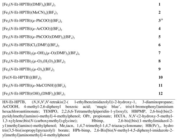
Here we report the synthesis and versatile reactivity of a DMF-coordinated diiron(II) compound, 1 (Chart 1), that features no bridging carboxylate. Reactions of 1 include reversible solvent exchange, substitution, reversible one and two electron oxidations, reaction with a radical oxidant, and dioxygen chemistry leading to the isolation and characterization of 9 new compounds (Scheme 1) including a Robin-Day40 Class II mixed valent diiron compound. Reaction of this diiron(II,III) species with dioxygen is described in detail for the first time. This report thus describes the synthesis, X-ray structure determinations, spectroscopic studies, cyclic voltammetry studies and reactivities of diiron complexes with or without bridging carboxylate ligands and the corresponding reactive intermediate species.
Chart 1.
Abbreviations and designations of compounds
Scheme 1.
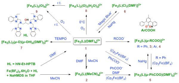
Schematic depiction of the syntheses of complexes 1-9 and 12 (Chart 1).
Experimental Section
Preparation of Compounds
All reactions and manipulations were performed under a pure dinitrogen atmosphere using either Schlenk techniques or an inert atmosphere box. Solvents were passed through a solvent purification system prior to use. In the preparations that follow, reactants were used as suspensions or solutions in solvents of specified volume, filtrations were performed through Celite, solvent removal steps were carried out in vacuo, and products were washed with ether and dried. HN-Et-HPTB was synthesized according to a literature procedure.33 Fe(BF4)2·6H2O, NaHMDS, tris(4-bromophenyl)aminium hexachloroantimonate (‘magic blue’), sodium benzoate, and anhydrous DMF were obtained from commercial sources and used without further purification. Yields are reported for recrystallized compounds. The identities of all 12 compounds in Chart 1 were confirmed by single crystal X-ray structure determinations. Compound 3 was previously reported34 without the DMF molecules in the lattice. A compound analogous to 5 was recently reported.31 Selected compounds were further characterized by elemental analysis and studied by electronic absorption, EPR, and Mössbauer spectroscopy. All Fe(II) compounds are extremely air-sensitive and must be handled accordingly.
[Fe2(N-Et-HPTB)(DMF)4](BF4)3 (1)
To a suspension of HN-Et-HPTB (0.2 mmol, 144 mg) in 2 mL of THF was added NaHMDS (0.2 mmol, 37 mg) in 2 mL of THF with stirring. After 1 min, Fe(BF4)2·6H2O (0.4 mmol, 135 mg) in 2 mL of THF was added and the resultant slurry was stirred for 2 h. This slurry was filtered and the solid collected, washed with cold THF, and dried. The solid was dissolved in DMF, filtered, and the filtrate was diffused overnight with Et2O at −45 °C with additional 1 day standing at r.t. to yield a pale yellow crystalline solid. This solid was recrystallized twice in the same manner to generate the product as colorless crystals (167 mg, 60%). Anal. Calcd. for C55H77B3F12Fe2N14O5 (1): C, 47.67; H, 5.60; N, 14.14. Found: C, 47.52; H, 5.32; N, 13.89.
[Fe2(N-Et-HPTB)(MeCN)4](BF4)3 (2)
To a suspension of HN-Et-HPTB (0.2 mmol, 144 mg) in 2 mL of THF was added NaHMDS (0.2 mmol, 37 mg) in 2 mL of THF with stirring. After 1 min, Fe(BF4)2·6H2O (0.4 mmol, 135 mg) in 2 mL of THF was added and the resultant slurry was stirred for 2 h. By following the work up procedure for 1, but using MeCN instead of DMF, the product was obtained as a colorless crystalline solid (160 mg, 60%).
Alternatively the compound could be prepared by dissolving [Fe2(N-Et-HPTB)(DMF)4](BF4)3 in MeCN followed by overnight diffusion of Et2O at −45 °C and 1 additional day of standing at r.t., affording the product as a colorless crystalline solid in similar yield.
Despite repeated attempts, it was not possible to obtain satisfactory elemental analyses.
[Fe2(N-Et-HPTB)(μ-PhCOO)](BF4)2 (3)
To a solution of [Fe2(N-Et-HPTB)(DMF)4](BF4)3 (0.05 mmol, 69 mg) in 2 mL of MeCN was added PhCOONa (0.05 mmol, 7 mg) in 2 mL of MeCN and the mixture was stirred for 6 h. The yellowish solution was evaporated to dryness. The residue was extracted with 1 mL of DMF, filtered, and the filtrate was diffused overnight with Et2O at −45 °C and allowed to stand for a day at r.t. to afford the product as a light yellow crystalline solid (42 mg, 66%).
Alternatively, this compound can be prepared directly from HN-Et-HPTB, Fe(BF4)2·6H2O, PhCOOH, and Et3N in methanol by following a method reported earlier.34 The product was recrystallized by Et2O diffusion into a DMF solution as light yellow needles in 78% yield.
[Fe2(N-Et-HPTB)(μ-ArCOO)](BF4)2 (4)
To a mixture of HN-Et-HPTB (0.2 mmol, 144mg) and 4-methyl-2,6-diphenyl benzoic acid (0.2 mmol, 58 mg) suspended in 4 mL of THF was added NaHMDS (0.4 mmol, 74 mg) in 2 mL of THF with stirring. After 1 min, Fe(BF4)2·6H2O (0.4 mmol, 135 mg) in 2 mL of MeCN was added causing a transient violet color which eventually affords a colorless solution and subsequently a nearly colorless slurry upon stirring for 6 h. By following the work-up procedure for 3, the product was obtained as a colorless crystalline solid (235 mg, 81%). Anal. Calcd. for C69H78B2F8Fe2N12O5 (4·2 C3H7NO): C, 57.52; H, 5.46; N, 11.67. Found: C, 57.18; H, 5.16; N, 11.55.
Fe2(N-Et-HPTB)(μ-PhCOO)(DMF)2](BF4)3 (5)
To a solution of [Fe2(N-Et-HPTB)(DMF)4](BF4)3 (0.05 mmol, 69 mg) in 2 mL of MeCN was added, with stirring, a suspension of PhCOONa (0.05 mmol, 7 mg) in 2 mL of MeCN followed by addition of a solution of (Cp2Fe)(BF4) (0.05 mmol, 14 mg) in 2 mL of MeCN. The mixture was stirred for 6 h. The greenish brown solution was evaporated to dryness and the residue thus obtained was thoroughly washed with THF to afford a brown solid. By following the work-up procedure for 3, the product was obtained as a brown crystalline solid (30 mg, 40 %).
Alternatively, this compound can be prepared from 3. A solution of (Cp2Fe)(BF4) (0.05 mmol, 14 mg) in 2 mL of MeCN was added to a solution of 3 (0.05 mmol, 64 mg) in MeCN and stirred for 4 h. By following the work-up procedure for 3 the product was obtained as dark red brown crystals (50 mg, 63%). Anal. Calcd. for C62H84B3F12Fe2N14O8 (5·2 DMF·H2O: C, 48.81; H, 5.55; N, 12.85. Found: C, 48.77; H, 5.13; N, 12.79.
[Fe2(N-Et-HPTB)Cl3(DMF)](BF4)2 (6)
To a solution of 1 (0.05 mmol, 69 mg) in 2 mL of MeCN was added a solution of tris(4-bromophenyl)aminium hexachloroantimonate (0.06 mmol, 49 mg) in 2 mL of MeCN. The mixture was stirred for 6 h. The orange solution was evaporated to dryness. By following the work up procedure for 3, the product was obtained as an orange crystalline solid (40 mg, 65%). This compound gave a slightly low carbon analysis. Anal. Calcd. for C46H56B2Cl3F8Fe2N11O2 (6): C, 46.52; H, 4.76; N, 12.98. Found: C, 45.87; H, 4.78; N, 12.91.
[Fe5(N-Et-HPTB)2(μ-OH)4(μ-O)(DMF)2](BF4)4 (7)
To a solution of [Fe2(N-Et-HPTB)(DMF)4](BF4)3 (0.05 mmol, 69 mg) in 1 mL of DMF was added a solution of TEMPO (0.1 mmol, 16 mg) in 1 mL of DMF and the mixture was stirred for 12 h. This solution was diffused for 2 d with Et2O at −45 °C with additional 1 day standing at r.t. to obtain the product as light red crystals. This compound was characterized by an X-ray structure determination.
[Fe4(N-Et-HPTB)2(μ-O)4](BF4)2 (9)
Dioxygen was bubbled into a solution of [Fe2(N-Et-HPTB)(DMF)4](BF4)3 (0.05 mmol, 69 mg) in 1 mL of DMF for 1 min. This solution was diffused with Et2O at r.t. for 2 d to obtain the product as red-brown crystals (34 mg, 66%).
When dioxygen was bubbled into a solution of identical composition that had been pre-cooled to 0 °C followed by ether diffusion at 0 °C for 2 d and subsequent standing at r.t. for 1 day, the product obtained was a mixture of [Fe4(N-Et-HPTB)2(μ-O)4](BF4)2 (major product) and [Fe4(N-Et-HPTB)2(μ-O)3(H2O)2](BF4) (8) (minor product). The latter was identified by an X-ray structure determination only and was never obtained in appreciable quantities as a pure compound.
[Fe(N-Et-HPTB)](BF4)2 (10) and [Fe2(N-Et-HPTB)(μ-MeCONH)](BF4)2 (11)
To a suspension of HN-Et-HPTB (0.5 mmol, 361 mg) in 2 mL of THF was added NaHMDS (0.51 mmol, 94 mg) in 2 mL of THF. After 1 min, Fe(BF4)2·6H2O (1 mmol, 336 mg) in 4 mL of MeCN was added and the mixture was stirred for 4 h. The reaction mixture was then evaporated to dryness. The residue obtained was insoluble in THF, MeCN, and DCM. It was dissolved in DMF, filtered, and the filtrate was diffused overnight with Et2O at −45 °C with an additional 1 d standing at r.t. to afford a mixture of [Fe2(N-Et-HPTB)(DMF)4](BF4)3, [Fe2(N-Et-HPTB)(MeCONH)](BF4)2, and [Fe(N-Et-HPTB)](BF4)2. The latter two compounds were identified by X-ray structure determinations only. No attempts were made to prepare them in pure form.
[Fe2(N-Et-HPTB)(OH)2(DMF)2](BF4)3 (12)
To a solution of 5 (0.05 mmol, 79 mg) in 2 mL of MeCN was added, with stirring, a solution of (Cp2Fe)(BF4) (0.06 mmol, 17 mg) in 2 mL of MeCN. The mixture was stirred for 24 h. By following the work-up procedure for 5, the product was obtained as a brown crystalline solid (26 mg).
Alternatively, this compound can be prepared from 3. A solution of (Cp2Fe)(BF4) (0.12 mmol, 33 mg) in 2 mL of MeCN was added to a solution of 3 (0.05 mmol, 4 mg) in MeCN and stirred for 24 h. By following the work-up procedure for 5 the product was obtained as a brown crystalline solid (24 mg).
Irrespective of the procedure, 12 was never obtained as pure material in bulk quantities and was contaminated with 5 as identified by unit cell determination, solution stability comparisons in presence of O2, and cyclic voltammetry. Compound 12 was characterized only by the single crystal X-ray structure determination.
General Physical Methods
Electronic absorption spectra were recorded on either a Cary 1 or a Cary 50 spectrophotometer using 6Q Spectrosil quartz cuvettes (Starna) with a 1 cm path length. X-band EPR spectra were recorded at 77 K on a Bruker EMX spectrometer. Electrochemical measurements were performed with 1 mM solutions of samples in DMF using a VersaSTAT3 Princeton Applied Research potentiostat running the V3-Studio electrochemical analysis software. A three-electrode setup was employed comprising a platinum working electrode, a platinum wire auxiliary electrode, and a silver rod as the pseudo reference electrode. Tetra-n-butylammonium hexafluorophosphate (0.1 M) was used as the supporting electrolyte. Electrochemical potentials are referenced internally to the ferrocene/ferrocenium couple at 0.00 V.
57Fe Mössbauer Spectroscopy
Mössbauer spectra were recorded on an MSI spectrometer (WEB Research Co.) with a 57Co source in a Rh matrix maintained at r.t.. Solid samples were prepared by suspension of the complex (40-50 mg) in Apiezon M grease and placed in a nylon sample holder. All samples contained natural abundance iron and were measured over the course of 1-2 d. Data were acquired at 77 K and isomer shift (δ) values are reported with respect to an α-Fe foil that was used for velocity calibration at r.t. Spectra were fit to Lorentzian line shapes using the WMOSS plot and fit program.
Resonance Raman Spectroscopy
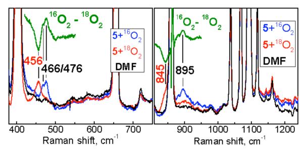
Resonance Raman samples were prepared by injecting 6 mM DMF solutions of Compound 5 in NMR tubes filled with 16O2 or 18O2 gas. The reaction was allowed to proceed for 6 min at room temperature before freezing the samples in liquid nitrogen. Resonance Raman spectra were collected on a McPherson 2061/207 spectrometer equipped with a Princeton Instrument liquid-N2-coooled CCD detector (LN-1100 PB). The 647-nm excitation was provided by a Coherent Innova 302C krypton ion laser and a matching long wave pass filter (RazorEdge filter, Semrock) was used to attenuate the Rayleigh scattering. Frequencies were calibrated relative to several frequency standards and are accurate to ± 1 cm−1. The samples were placed in a copper cold finger cooled with liquid nitrogen to maintain the sample temperature at ~110 K during data acquisition. Individual spectra obtained at different laser power and with or without sample spinning were compared to confirm the integrity of the samples during data acquisition.
X-ray Structure Determinations
The structures of compounds shown in Chart 1 were determined. Diffraction-quality crystals were obtained by ether diffusion into MeCN or DMF solutions as described in the respective syntheses. Single crystals were mounted in Paratone oil using 30 μm aperture MiTeGen MicroMounts (Ithaca, NY) and frozen under a 100 K KRYO- FLEX nitrogen cold stream. Data were collected on a Bruker SMART APEX CCD X-ray diffractometer with Mo Kα radiation (λ= 0.71073 Å) controlled by the APEX 2 (v. 2010.1-2) software package. Raw data were integrated and corrected for Lorentz and polarization effects using the Bruker APEX II program suite.41 Absorption corrections were performed using SADABS. Space groups were assigned by analysis of metric symmetry and systematic absences (determined by XPREP) and were further checked by PLATON42,43 for additional symmetry. Structures were solved by direct methods and refined against all data in the reported 2θ ranges by full-matrix least squares on F2 with the SHELXL program suite44 using the OLEX 2 interface.45 Hydrogen atoms at idealized positions were included in final refinements. The OLEX 2 interface was used for structure visualization and drawing ORTEP plots.46,47 Crystallographic data and final agreement factors for complexes 1-12 are given in Tables 1-2 along with explanations for restraints used and positions of residual electron densities. Most of the compounds contain disordered anions, solvents and/or parts of a ligand and are mentioned for individual compounds in the footnotes of Tables 1-2. These features were taken care of by disorder modeling using free variables (PART instructions) along with appropriate restraints (SADI and EADP). Compound 5 contains 2 independent molecules in its asymmetric unit (Pī , Z =4). These two independent units display different Fe—O bond distances. X-ray structures of 2, 6, 8, 9 and 12 contained several severely disordered solvent molecules. Their contributions to the structure factors were taken into account by either applying the MASK procedure in the OLEX2 program package (2, 8, 9, 12) or by using the SQUEEZE procedure in PLATON (6). Solvent accessible voids and total electron counts per cell for 2, 6, 8, 9 and 12 are 736.6 Å3, 115.7; 657 Å3, 224; 2485.6 Å3, 183.8; 1888.6 Å3, 279.2; 541.0 Å3, 86.9, respectively. Refinement details and explanations (wherever necessary) are included in the individual CIFs.
Table 1.
X-ray crystallographic data for compounds 1-6 (Chart 1) at 100 Ka
| Compounds | 1 | 2·2MeCN | 3·2DMF | 4·2DMF | 5·3DMF | 2 (6)·Et2O |
|---|---|---|---|---|---|---|
| formula | C55H77B3 F12Fe2N14O5 |
C55H67B3 F12Fe2 N16O |
C56H68B2 F8Fe2 N12O5 |
C69H78B2 F8Fe2 N12O5 |
C65H89B3 F12Fe2 N15O8 |
C96H122B4 Cl6F16Fe4 N22O5 |
| formula weight | 1386.44 | 1340.38 | 1274.54 | 1440.75 | 1580.64 | 2447.50 |
| crystal system | triclinic | triclinic | triclinic | triclinic | triclinic | monoclinic |
| space group | Pī | Pī | Pī | Pī | Pī | P21/c |
| a, Å | 12.629(8) | 14.656(6) | 13.016(1) | 12.150(2) | 19.182(9) | 19.606(8) |
| b, Å | 15.415(10) | 16.035(6) | 13.827(2) | 16.280(2) | 19.943(9) | 21.522(9) |
| c, Å | 17.705 (1) | 16.885(6) | 18.859(2) | 17.653(2) | 20.448 (9) | 17.649(7) |
| α, deg | 78.326(1) | 112.807(1) | 72.271(2) | 98.098(2) | 99.085(1) | |
| β, deg | 86.512(1) | 94.447(1) | 80.965(2) | 95.663(2) | 105.025(1) | 114.826(1) |
| γ, deg | 68.977(1) | 110.424(1) | 67.018(2) | 101.203(2) | 97.781(1) | |
| V, Å3 | 3150.5(4) | 3321.4(2) | 2973.4(6) | 3362.3(8) | 7331.1(6) | 6759.2(5) |
| Z | 2 | 2 | 2 | 2 | 4 | 2 |
| ρcalcd, gm/cm3 | 1.462 | 1.340 | 1.424 | 1.423 | 1.432 | 1.203 |
| μ, mm−1 | 0.555 | 0.520 | 0.571 | 0.514 | 0.490 | 0.611 |
| θ range, deg | 1.67-25.69 | 1.51-25.69 | 1.66-26.01 | 1.60-25.73 | 1.63-25.62 | 1.14-25.74 |
| completeness to θ, % |
99.8 | 99.8 | 99.1 | 99.0 | 99.8 | 99.9 |
| reflections collected |
51577 | 55393 | 44835 | 53875 | 119525 | 108108 |
| independent reflections |
11969 | 12625 | 11587 | 12706 | 27612 | 12909 |
| R(int) | 0.0251 | 0.0250 | 0.0470 | 0.0297 | 0.0298 | 0.0405 |
| drestraints | 7 | 0 | 11 | 0 | 56 | 16 |
| parameters | 844 | 830 | 835 | 892 | 1949 | 771 |
| Max., min. transmission |
0.9570, 0.8602 |
0.9498, 0.8596 |
0.9451, 0.7954 |
0.9797, 0.8865 |
0.9619, 0.8512 |
0.9760, 0.7921 |
| R1b(wR2)c [I>2sigma(I)] |
0.0513 (0.1236) |
0.0348 (0.0927) |
0.0728 (0.1650) |
0.0381 (0.1016) |
0.0577 (0.1545) |
0.0595 (0.1899) |
| R1b(wR2)c | 0.0597 (0.1301) |
0.0411 (0.0958) |
0.1290 (0.2235) |
0.0483 (0.1090) |
0.0733 (0.1689) |
0.0708 (0.1999) |
| GOF(F2)d | 1.028 | 1.056 | 1.013 | 1.044 | 1.055 | 1.065 |
|
emax, min peaks, e.Å−3 |
1.924, −1.825 |
0.918, −0.726 |
1.241, −0.800 |
0.862, −0.488 |
1.919, −2.161 |
2.330, −0.870 |
Mo Kα radiation (λ = 0.71073 Å).
R1 = Σ∥Fo∣-∣Fc∥/Σ∣Fo∣.
wR2 = {Σ[w(Fo2-Fc2)2]/Σ[w(Fo2)2]}1/2.
GOF = {Σ[w(Fo2–Fc2)2]/(n–p)}1/2, where n is the number of data and p is the number of refined parameters.
1, Disordered DMF; 3, disordered BF4−(2), N-Et group (3), DMF (1), and phenyl ring (1); 5, disordered BF4− (1), DMF (1), N-Et group (1); 6, disordered DMF (2), N-Et group (1), Et2O (1).
1, Electron density near one BF4−, disorder modeling was not reasonable; 3, Electron density near one of the phenyl rings, disorder modeling was not reasonable; 5, near one of the disorder modeled BF4−; 6, near disorder modeled diethyl ether, reasonable modeling was not found.
Table 2.
X-ray crystallographic data for compounds 7-12 (Chart 1) at 100 Ka
| Compounds | 7·3DMF·Et2O | 8·2DMF | 9·2DMF | 10·4MeCN | 11·DMF | 12·2DMF |
|---|---|---|---|---|---|---|
| Formula | C105H150B4 F16Fe5 N25O13 |
C92H116B2 F8Fe4 N22O9 |
C92H112B2 F8Fe4N22O8 |
C51H62B2 F8Fe N14O |
C48H60B2 F8Fe2 N12O3 |
C55H78B3 F12Fe2 N14O7 |
| formula weight | 2596.99 | 2071.09 | 2051.06 | 1116.62 | 1138.40 | 1419.44 |
| crystal system | triclinic | triclinic | triclinic | orthorhombic | monoclinic | Triclinic |
| space group | Pī | Pī | Pī | Pbcn | P21/n | Pī |
| a, Å | 17.548(2) | 15.092(2) | 17.282(1) | 23.978(2) | 13.879(1) | 12.821(4) |
| b, Å | 18.524(2) | 17.612(3) | 17.599(1) | 11.555(8) | 23.342(2) | 17.528(6) |
| c, Å | 20.896(2) | 27.955(4) | 23.455(3) | 19.580(1) | 15.968(1) | 17.703(6) |
| α, deg | 78.952(2) | 85.993(3) | 100.636(2) | 73.288 (1) | ||
| β, deg | 71.109(2) | 80.605(2) | 95.959(2) | 97.122(2) | 76.650(1) | |
| γ, deg | 69.479(2) | 64.731(2) | 116.188(1) | 79.532(1) | ||
| V, Å3 | 5995.2(1) | 6629.1(2) | 6151.0(1) | 5425.0(6) | 5133.0(8) | 3678.9(2) |
| Z | 2 | 2 | 2 | 4 | 4 | 2 |
| ρcalcd, gm/cm3 | 1.439 | 1.257 | 1.107 | 1.367 | 1.473 | 1.281 |
| μ, mm−1 | 0.684 | 0.506 | 0.527 | 0.357 | 0.649 | 0.478 |
| θ range, deg | 1.63-25.76 | 1.48-25.80 | 1.61-24.75 | 1.70-25.71 | 1.55-25.69 | 1.49-25.70 |
| completeness to θ , % |
99.1 | 99.0 | 98.6 | 100.0 | 100.0 | 99.8 |
| reflections collected |
95976 | 25264 | 92034 | 84107 | 83460 | 58867 |
| independent reflections |
22796 | 107121 | 20801 | 5165 | 9751 | 13988 |
| R(int) | 0.0585 | 0.0630 | 0.0457 | 0.0422 | 0.0469 | 0.0365 |
| drestraints | 16 | 6 | 3 | 3 | 46 | 17 |
| Parameters | 1509 | 1269 | 1161 | 360 | 668 | 791 |
| max., min. transmission |
0.9731, 0.8210 | 0.9899, 0.8629 |
0.9691, 0.8169 |
0.9858, 0.9385 | 0.9745, 0.9262 |
0.9811, 0.9104 |
| R1b(wR2)c [I>2sigma(I)] |
0.0841 (0.2271) |
0.0809 (0.2559) |
0.0762 (0.2433) |
0.0652 (0.1622) |
0.0912 (0.2200) |
0.0848 (0.2554) |
| R1b(wR2)c | 0.1140 (0.2484) |
0.1157(0.278 9) |
0.0959 (0.2587) |
0.0776 (0.1737) |
0.1089 (0.2335) |
0.1110 (0.2771) |
| GOF(F2)d | 1.073 | 1.116 | 1.096 | 1.057 | 1.051 | 1.143 |
|
emax, min peaks, e.Å−3 |
1.821 , −1.137 |
1.096, −0.675 | 1.118, −1.136 | 1.467, −0.951 |
1.232, −1.101 |
1.473, −1.418 |
Mo Kα radiation (λ = 0.71073 Å).
R1 = Σ∥Fo∣-∣Fc∥/Σ∣Fo∣.
wR2 = {Σ[w(Fo2-Fc2)2]/Σ[w(Fo2)2]}1/2.
GOF = {Σ[w(Fo2–Fc2)2]/(n–p)}1/2, where n is the number of data and p is the number of refined parameters.
7, disordered DMF (2), diethyl ether (1); 8, disordered DMF (2), N-Et group (2); 9, disordered DMF(1), N-Et group (1); 10, MeCN (3); 11, disordered DMF (1), BF4− (2), N-Et (2), N-CH (4); 12, disordered DMF (1), perchlorate (3).
7, near one BF4−, disorder modeling was not reasonable; 8, near iron; 9, near BF4−, disorder modeling was not helpful; 10, near alkoxide group, not taken into account; 11, near severely disordered benzimidazole; 12, near hydroxide groups, no meaningful disorder modeling found; 13, near one of the perchlorates, disorder modeling was not helpful.
RESULTS AND DISCUSSION
Synthesis
Compound 1 was prepared by addition of an iron(II) salt to a solution of deprotonated HNEt-HPTB in THF. The choice of solvent is of utmost importance because the same reaction in MeCN or in a 1:1 mixture of THF and MeCN yields a mixture of compounds 1, Fe(N-Et-HPTB)](BF4)2 (10), and [Fe2(N-Et- HPTB)(μ-MeCONH)](BF4)2 (11). The bridging acetamide in 11 was probably generated by base-catalyzed (NaHMDS) partial hydrolysis of MeCN. Hydrolysis of MeCN in the presence of iron compounds is precedented.48 This problem was avoided by use of THF as the sole solvent and filtration followed by thorough washing with THF to obtain a pale greenish yellow solid prior to use of MeCN or DMF as the solvent for crystallization to obtain 2 or 1, respectively, as colorless crystals. To the best of our knowledge, 1 and 2 do not have any precedent in the literature except for a diiron(III) compound, reported only recently39 while this manuscript was in preparation. Compound 1 offers a rich chemistry involving solvent exchange, substitution, dioxygen reactivity, and controlled redox reactions leading in this study to the isolation and X-ray structural characterization of 9 compounds (2-9, 12), as presented in Scheme 1. Electronic absorption spectroscopic signatures of selected compounds are provided in Supporting Information (Fig. S1). The coordinated DMF molecules in 1 are easily displaced by MeCN to yield compound 2 by simple dissolution of 1 in MeCN and diffusion of Et2O into the resulting solution. Alternatively, 2 can be directly prepared as described in the Experimental Section.
Compound 1 can be treated as a basic framework for preparing carboxylate-bridged diiron complexes, as shown by the syntheses of 3 with a bridging benzoate and 4 with a sterically demanding m-terphenyl carboxylate. The most important aspect of the reactivity of 1 is the possibility of one- and two-electron oxidations. One-electron oxidation of 1 with one equivalent of (Cp2Fe)(BF4), followed by immediate addition of sodium benzoate, yielded the class II mixed valent (FeIIFeIII) compound (5). Alternatively, 5 can be prepared by reaction of 334 and one equivalent of Cp2Fe(BF4). Use of two equivalents of Cp2Fe(BF4) leads to loss of the carboxylate bridge, as shown by the isolation of the diiron(III) compound 12 in low yield. The hydroxo groups in 12 may have originated either from water carried over from Fe(BF4)2·6H2O used to prepare 1 and 334 or from adventitious moisture in otherwise dry solvents. Compound 5 can be converted back to 334 by treatment with one equivalent of NaHg as confirmed by X-ray structural analysis. On the other hand, reaction of 1 with one equivalent of ‘magic blue’ (Chart 1) yielded an orange-colored diiron(III) compound (6) in 65% yield. In this reaction, both tris(4-bromophenyl)aminium cation (E0red = 0.70 V vs. ferrocene)49 and hexachloroantimonate anion may each have acted as one-electron oxidants accompanied by chloride abstraction by the resulting iron(III) centers. Another possibility is that the hexachloroantimonate anion serves as two-electron oxidant, with concomitant chloride abstraction by the iron(III) centers. These modes of reaction by SbCl6− coupled with subsequent halogenation in the case of organometallic complexes are well documented.50 Interestingly, reduction of 6 using NaHg gives back compound 1, as confirmed by a unit cell determination of a single crystal grown from Et2O diffusion into a DMF solution of the isolated colorless product. Formation of 11 is frequently also observed along with 1. This reaction can be visually monitored by the gradual bleaching of the dark orange red color of 6 to yield a nearly colorless solution upon addition of NaHg in portions until a total of 2.5 equivalents are used. Reaction of TEMPO with 1 was not well behaved, and only trace amounts of a red crystalline product (7) were isolated at an unconvincing stoichiometry of reactants. This chemistry was not further pursued.
Dioxygen Reactivity of 1
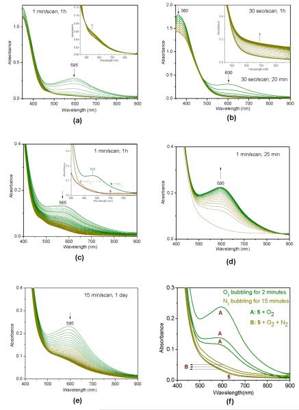
Compound 1 is highly reactive toward O2, as monitored by absorption spectroscopy in both coordinating (DMF, Fig. 1a) and non-coordinating (DCM, Fig. 1b) solvents. Upon bubbling O2 through a colorless solution of 1 in DMF, the solution immediately developed a dark green color corresponding to a visible band at 595 nm (600 nm in DCM solution), suggesting the formation of a peroxo species. Appearance of a visible band at 588 nm was reported upon exposure of a DCM solution of 334 to O2 at −60 °C, whereas a visible band at 570 nm was observed upon similar conditions in the case of diferrous propionate analog of 3.34 These observations suggest the presence of a spectral band arising from a peroxo-to-Fe(III) charge-transfer transition.34 The difference between the absorption maxima (600 nm in the case of 1 + O2, compared with 588 and 570 nm) in the same solvent (DCM) and same ligand system (HN-Et-HPTB) can be attributed to the absence of a bridging carboxylate in 1. Dioxygen presumably binds to the open coordination sites of 1 and is reduced to the peroxide oxidation state by the iron centers. At r.t., the green color of the solution slowly changes to light brown within 1 h and then to red-brown over the course of 8 h. Similar observations were noted upon changing the solvent from DMF to DCM, although, as expected, the dark green peroxo compound seemed to be less stable in non-coordinating and less polar DCM as compared to coordinating and more polar DMF. This result is consistent with previous reports that highly polar solvents such as DMF or DMSO stabilize dioxygen adducts.34 Two compounds have been isolated and characterized (8 and 9) that may correspond to those responsible for the color changes (light brown, 8, 2FeII, 2FeIII; red-brown, 9, all FeIII) observed during the UV-Vis spectroscopic study (Fig. 1). Formation of such (μ-oxo)polyiron(III) species upon decomposition of related peroxo-diiron(III) compounds has been previously proposed.37 A recent report describes the dioxygen reactivity of several complexes of the type [FeII2(N-Et-HPTB)(μ-O2X)]2+ (O2X is an oxyanion bridge).38 These diiron(II) complexes react with O2 at low temperatures in DCM at −90 °C to form triply bridged (μ−η1:η1-peroxo)diiron(III) species. With one exception (O2X = O2AsMe2), all these triply bridged intermediates (λmax = 630-710 nm) convert irreversibly to doubly bridged species (λmax = 580-620 nm) by expulsion of the bridging O2X unit before decaying to yellow final products. Compound 1 does not have any bridging unit and it generates an absorption maximum at 595 nm in DMF (600 nm in DCM) solution upon reaction with dioxygen and thus is in good agreement. Dioxygen reactivity of 1 may be seen in this regard as the dioxygen reactivity of a diiron(II) compound that does not have a O2X bridging unit.
Figure 1.
Electronic absorption spectroscopic monitoring at r.t. of (a) decomposition of in situ generated peroxo species (1 + O2) in DMF, [1] = 0.0002 M; inset: magnified view of the second stage of decomposition; (b) decomposition of in situ generated peroxo species (1 + O2) in CH2Cl2, [1] = 0.0002 M; inset: second stage of decomposition in measured separately; (c) decomposition of the oxidized species formed by reaction of 5 ([5] = 0.0002 M) with KO2 (0.0005 M) in presence of 18-crown-6 (0.0005 M) in DMF; inset: absorption spectra for selected stages of the experiment; (d) reaction of 5 ([5] = 0.0002 M) with dioxygen (5 sec bubbling) forming a green solution in DMF; (e) decomposition of the green colored species upon standing at r.t.; (f) demonstration of quasi-reversibility for the formation of the green colored species by reaction of compound 5 with O2.
Reactivity of 5 with Superoxide and Dioxygen
Compound 5 reacts rapidly with superoxide to form an unstable green species, presumably a peroxo complex that decomposes within 1 h at r.t. to form a light brown/yellow solution (Fig. 1c). Compound 5 did not show any reactivity toward TEMPO. On the other hand, 5 reacted with dioxygen at r.t. (Fig. 1d) to form a dark green diiron(III,III) peroxo compound featuring an absorption maximum at 595 nm (ε = 2960 ± 210 L M−1 cm−1) resembling the spectroscopic signature obtained by treatment of 1 with O2. The green colored solution slowly decays with full bleaching of the band at 595 nm within 1 day at r.t. (Fig. 1f) and a color change to light brown. Appearance of a visible band at 588 nm was also reported upon exposure of a DCM solution of 334 to O2 at −60 °C. Compound 5 presumably generates a transient diiron(III) superoxo species, which in turn reacts with 5 to yield a meta-stable diiron(III) peroxo compound (green, λmax = 595 nm) and another diiron(III) compound. This sequence has been studied by resonance Raman spectroscopy, Mössbauer spectroscopy, EPR spectroscopy, and electrochemistry, and the results are discussed in the corresponding sections below. The formation of the dark green solution upon reaction of 5 with dioxygen could be partially reversed upon bubbling nitrogen through it for 15 min. Bubbling dioxygen for 2 minutes into this brown solution again generated the green species. Prolonged incubation times did not increase the absorbance of 595 nm band. Also, the more time spent, the more incapable the solution was of showing dioxygen reactivity owing to slow decomposition of the green solution, as shown in Fig. 1e. Unlike 5, 1 forms a highly unstable peroxo species that decomposes rapidly at r.t. (Fig. 1a) compared with decomposition of 5 + O2 (Fig. 1e). Complete reversibility was not observed, as seen by the slow decrease in the absorbance of the regenerated green species in Fig. 1f. This result is in agreement with its observed instability in solution, shown in Fig. 1e. Attempts to isolate the light brown species yielded very tiny brown crystals that were insufficient for single crystal X-ray structure analysis.
X-ray Structures
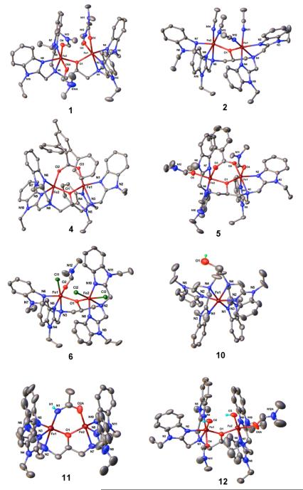
Molecular structures of 1-12 (except 334) are presented in Figs. 2 and 3. Selected bond distances and angles are provided in Tables S1 and S2, respectively, in Supporting Information. Compounds 1, 2, and 12 have very similar structures, with either DMF (1, 12) or MeCN (2) as coordinating solvents. Compounds 3,34 4, 5 and 11 have similar structures, differing only in the nature of the bidentate bridging ligand, which is either benzoate (3, 5), 2,6-diphenyl-4-methylbenzoate (4), or acetamide (11). In contrast to its acetonitrile analog reported recently,31 the crystallographic unit cell of 5 contains two independent molecules having different Fe—O bond distances. This situation occurs in X-ray structures of three different crystals from three different batches of 5. The two benzimidazoles are cis to each other on Fe(III) and trans to each other on Fe(II). The opposite situation was found in case of the acetonitrile analog.31 Compound 5 has been identified as a class II mixed valent FeIIFeIII species, based on X-ray structural, electrochemical, EPR, and Mössbauer spectroscopic analyses. Compound 5 displays two different Fe—Ocarboxylate distances (1.947(2), 2.069(2) and 1.961(2), 2.050(3) Å) and two different Fe—OLigand distances (1.929(2), 2.047(2) and 1.947(2), 2.035(2) Å) that also differ in the two crystallographically independent molecules. These results are consistent with the different sets of Fe—O bond distances observed in previously reported Class II mixed valent compounds.25,26
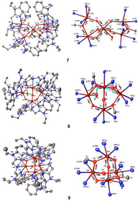
Figure 2.
Molecular structures of selected compounds with 50% probability thermal ellipsoids and partial atom-labeling schemes. Hydrogen atoms are omitted for clarity with a few exceptions.
Figure 3.
Molecular structures of selected compounds shown with 50% probability thermal ellipsoids and partial atom labeling schemes. Also shown are the core structures with bond distances. Hydrogen atoms are omitted for clarity with some exceptions.
The core structures of cluster compounds 7, 8, and 9 along with Fe—O bond distances are shown in Fig. 3. Compound 7 is a mixed oxo-hydroxo bridged cluster and contains a 2FeIII/3FeII configuration based on X-ray structural analysis. The differential protonation of the bridging ligands is manifest by the two shorter Fe—(μ-O) distances of 1.770(4) and 1.829(4) Å and 8 longer Fe—(μ-OH) distances ranging from 1.953(4) to 2.171(4) Å. Compound 8 is an oxo-bridged Fe4 cluster containing 2 FeII and 2 FeIII centers. This compound also displays four short FeIII—Obridging distances, ranging from 1.828(3)-1.831(3) Å, and two longer distances of 1.955(3) Å, whereas the Fe—OLigand distances are almost invariant (Fig. 3). Compound 9 is also an oxo-bridged Fe4 cluster that adopts an all-ferric adamantane core structure with a broad range of Fe—(μ-O) distances (1.805(3)-2.035(3) Å). Two sets of Fe(III) sites occur, with Fe—(μ-O) distances ranging from 1.805-1.812 Å, and 2.015-2.035 Å in one set, and1.902-1.910 Å and1.895-1.897 Å in the other set.
Mössbauer Spectroscopy
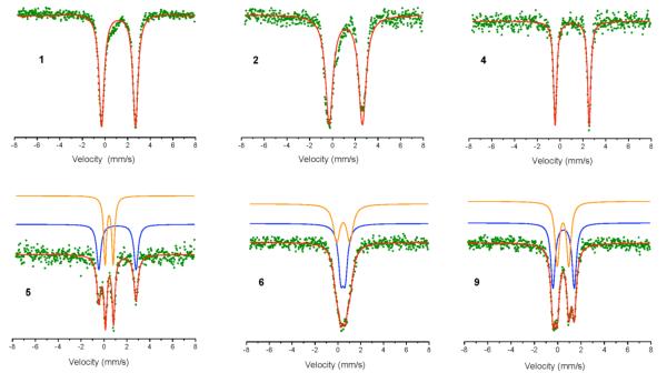
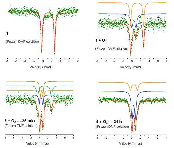
Compounds 1, 2, 4-6, and 9, and reactive species generated upon reaction of 1 and 5 with dioxygen, were examined by 57Fe Mössbauer spectroscopy at 77 K. The Mössbauer spectra are shown in Fig. 4 and Fig. 5 and the parameters are provided in Table 3. As expected, diiron(II) compounds 1 and 2 exhibit almost identical isomer shifts and quadrupole splittings. These parameters are also very similar to those of 4 (Table 3). Mössbauer data for all three of these compounds correspond to high spin iron(II). The diiron(III) compound 6 displays two-site spectra in a 1:1 ratio with identical isomer shifts but distinctly different quadrupole splitting values (Table 3) as a result of the different coordination environments of the two iron sites (Fig. 2). Compound 9 gives rise to two quadrupole doublets with very similar isomer shifts but different quadrupole splitting values (Table 3) owing to the presence of two sets of Fe(III) sites.
Figure 4.
57Fe Mössbauer spectra of selected compounds as solid samples at 77 K.
Figure 5.
57Fe Mössbauer spectra of selected compounds and reactive intermediates at 77 K.
Table 3.
Mössbauer parameters at 77K for selected compounds and reactive intermediates.
| compound | δ (mm/s) | ΔEQ (mm/s) | area (%) |
|---|---|---|---|
| 1 | 1.19 | 2.99 | 100 |
| 2 | 1.17 | 2.92 | 100 |
| 4 | 1.06 | 2.99 | 100 |
| 5 | 1.17 0.48 |
3.25 0.71 |
50 50 |
| 6 | 0.46 0.47 |
0.37 1.17 |
50 50 |
| 9 | 0.51 0.45 |
1.82 0.99 |
50 50 |
| 1 * | 1.21 | 2.94 | 100 |
| 1 + O2 * | 1.19 0.46 |
3.02 0.97 |
54 46 |
| 5 + O2-----25 min * | 1.22 0.52 0.40 0.57 |
3.24 0.53 0.82 0.91 |
32 32 18 18 |
| 5 + O2-----24 hours * | 0.44 0.49 |
0.76 1.59 |
70 30 |
samples loaded in frozen DMF
Mössbauer spectra of 5 at 77 K exhibit two well resolved doublets (Fig. 4) in a 1:1 ratio with δ = 0.48 mm/s, ΔEQ = 0.71 mm/s and δ = 1.17 mm/s, ΔEQ = 3.25 mm/s respectively, consistent with a high spin Fe(II)-Fe(III) formulation.51 This observation is in accord with parameters observed in the case of its acetonitrile analog [Fe2(N-Et-HPTB)(μ-PhCOO)(MeCN)2](ClO4)331 (120 K, δ = 0.46 mm/s, ΔEQ = 0.52 mm/s; δ = 1.11 mm/s, ΔEQ = 3.06 mm/s) and other mixed valent compounds such as [FeIIFeIIIBPMP(OPr)2(BPh4)225, [Na][Me4N][Fe2(HXTA)(OAc)2]29, [FeIIFeIIIL-py(CH3COO)2](BF4)228, and [FeIIFeIIIL-py(PhCOO)2](BF4)228. The observation of discrete quadrupole doublets for 5 at 77 K as well as at r.t. (Fig. S2) indicates that intervalence electron transfer is slow on the Mössbauer time scale (107 s−1) at 77 K, similar to the reported case of [FeIIFeIII(BPMP)(OPr)2](BPh4)2.25 Measurements at r.t., however, show coalescence of the doublets to a small extent, (δ = 0.32 mm/s, ΔEQ = 0.71 mm/s; δ = 1.12 mm/s, ΔEQ = 2.56 mm/s) suggesting the onset of intermediate electron exchange in 5. The observed decrease in isomer shift is also in agreement with the fact that, owing to the second order Doppler effect, Mössbauer isomer shifts diminish by approximately 0.0006 mm/s for each 1 K increase in temperature.52 Similar coalescence effects were observed with Na(Me4N)[Fe2(HXTA)(OAc)2],26 whereas emergence of a valence-detrapped doublet in addition to valence-trapped doublets at r.t. occurs in the case of [FeIIFeIII(bimp)(μ-O2CCH3)2](ClO4)2.27 Reaction of 5 with dioxygen was examined by Mössbauer spectroscopy (Fig. 5). Formation of a green solution upon bubbling dioxygen into a DMF solution of 5 was monitored by UV-Vis spectroscopy (development of λmax = 595 nm absorbance); after 25 min (as shown in Fig. 1d,) the solution was frozen at 77 K and Mössbauer data were collected. The parameters and nature of the fitting suggested that the green solution contains a mixture of unreacted 5, a diiron(III) peroxo species, and another high spin Fe(III) species. This result can be explained by initial formation of a diiron(III) superoxo species that immediately reacts with remaining 5, to form a diiron(III) peroxo species (δ = 0.57 mm/s) and another diiron(III) species (δ = 0.40 mm/s). Mössbauer parameters displayed by the diiron(III) peroxo species are very similar to those of an X-ray structurally characterized cis-1,2-μ-peroxo diiron(III) compound.53 Data were collected again after keeping the sample at r.t. for 24 h to characterize the light brown species. This sample required two site fitting with nearly equal isomer shifts but with different quadrupole splittings indicating formation of a high spin iron(III) compound/compounds with different coordination environments for the iron centers.
Formation of a peroxo complex upon reaction of 1 with dioxygen was also examined by Mössbauer spectroscopy (Fig. 5). In this experiment, a concentrated DMF solution (70 mg of 1 in 2 mL of DMF) was frozen in liquid nitrogen and Mössbauer data were collected. The sample was then warmed to 0 °C under nitrogen, and dioxygen gas was bubbled into it for 2 sec. The resulting dark green solution was immediately frozen in liquid nitrogen and Mössbauer data were measured. The frozen green solution exhibited two quadrupole doublets with one site having virtually identical isomer shifts and quadrupole splittings as observed for 1, either as a solid sample or a frozen DMF solution. The other site displayed an isomer shift of 0.46 mm/s and a quadrupole splitting of 0.97 mm/s, indicating the formation of a diiron(III) peroxo species. Possible contamination by 8 and 9 can be neglected considering their characteristics, especially the nonquivalent iron sites in 8, Mössbauer parameters observed for 9, and much longer time required for formation of 9 even at r.t. Mössbauer parameters for an X-ray structurally characterized cis-1,2-μ-peroxo diiron(III) compound, [Fe2(Ph-bimp)(C6H5COO)(O2)](BF4)2 are reported as δ = 0.58 mm/s, ΔEQ = 0.74 mm/s; δ = 0.65 mm/s, ΔEQ = 1.70 mm/s, ratio of areas 1.1:1, and are assigned to two distinct high-spin iron(III) centers consistent with different Fe—Opereoxo bond distances observed by X-ray structural characterization.53 The lower isomer shift in the putative peroxo compound obtained from 1 can be attributed to the increased electron density around the Fe(III) centers. This increased electron density is due to the absence of a carboxylate bridge, with its electron withdrawing properties, and the presence of alkoxide ligation and ethyl substituted imidazole based ligand, both electron donating, instead of phenoxide ligation and phenyl substituted imidazole based ligand, both less electron donating. Similar arguments may be invoked to explain the difference in isomer shift (0.66 mm/s) and quadrupole splitting (1.40 mm/s) from that reported for [Fe2(μ-1,2-O2)(μ-O2CCH2Ph)2{HB(pz’)3}2].54 Also, X-ray structural characterization of the peroxo compound generated by reaction of 3 with dioxygen in presence of triphenylphosphine oxide (Ph3PO) in MeCN revealed the formulation, [Fe2(O2)(N-Et-HPTB)(Ph3PO)2](BF4)3.35 Contrary to expectations, the benzoate bridge was absent in the crystalline O2 adduct. This result also suggests that 1 may form an analogous peroxo compound, which might have the formula, [Fe2(O2)(N-Et-HPTB)(DMF)2](BF4)3.
Electrochemistry
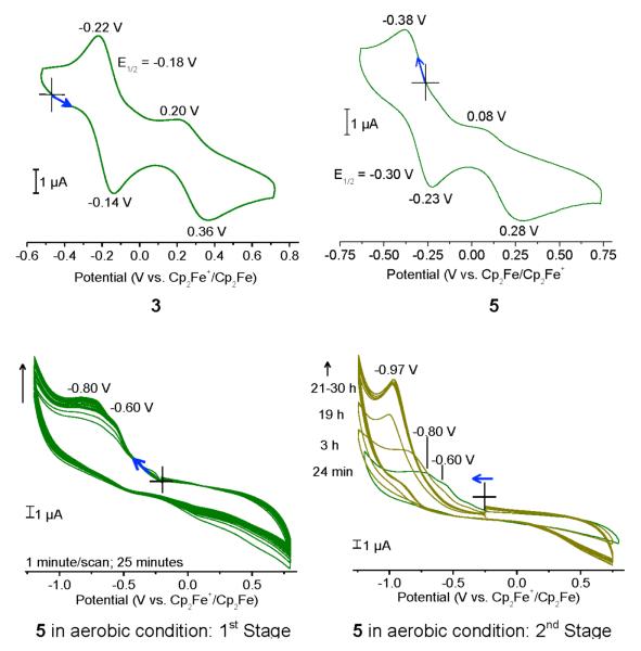
Cyclic voltammetric traces for compounds 3 and 5, obtained using a glassy carbon working electrode, are shown in Fig. 6. Compound 3 exhibited a reversible oxidation at E1/2 = −0.18 V (ΔE = 80 mV, ipa/ipc = 1.1; E1/2 = −0.31 V, ΔE = 60 mV, ipa/ipc = 1.1 with Pt working electrode) along with a quasi-reversible oxidation at 0.36 V (0.17 V with Pt working electrode). The redox processes involved during the cyclic voltammetry of 3 can most likely be presented as follows:
 |
These two well-separated redox processes explain the generation of a stable mixed valent species. The assignment of electrochemical reduction and oxidation events of compound 3 is further supported by electrochemical investigations of 5. The mixed valent FeIIFeIII compound 5 shows a quasi-reversible reduction at E1/2 = −0.30 V with ΔE = 150 mV and ipc/ipa = 1.2 (E1/2 = −0.29 V, ΔE = 100 mV, ipa/ipc = 1.1 with Pt working electrode). Additionally, an irreversible oxidation event occurred at 0.28 V (0.18 V with Pt working electrode). The similarity of both cyclic voltammograms thus further supports the presence of a FeIIFeIII species in case of compound 5 and generation of the same species during one electron oxidation of 3. In addition, the cyclic voltammograms highlight the potential of both the compounds to adopt a FeIIFeII, a mixed valent FeIIFeIII, as well as an FeIIIFeIII state. For both compounds, the oxidation of FeIIFeIII species, generates an unstable FeIIIFeIII species, which could not be isolated and was visible as an irreversible reduction of the FeIIIFeIII species in the cyclic voltammetric experiments.
Figure 6.
Cyclic voltammetric traces of 3 and 5 (glassy carbon working electrode) in DMF. Also shown is the monitoring of dioxygen reactivity of 5 (Pt working electrode). Scan rate = 100 mV/s, except in the case of 4 (50 mV/s).
The dioxygen reactivity of 5 was also examined by electrochemistry in a DMF solution of 5 through which dioxygen was bubbled. The cyclic voltammograms using Pt working electrode appear in Fig. 6. Facile generation of at least two irreversible reduction peaks occurred within 25 min at −0.60 V and −0.80 V respectively. Within 24 h these two peaks gradually vanish and a new reduction peak at −0.97 V is generated. These findings can be rationalized by assuming the formation of an unstable diiron(III) species within 25 min that is converted to a more stable diiron(III) complex with time.
EPR Spectroscopy
Mixed valent diiron(II,III) compounds encountered in small molecules24,26-28,30,31 and in biological samples55 are often successfully characterized by EPR spectroscopy. Most mixed valent Fe(II,III) compounds in a low symmetry ligand field exhibit signals with <gav> less than 2, characteristic of an S = ½ system that results from antiferromagnetic coupling of a high spin Fe(III) ion (S = 5/2, 6A state) with a high spin Fe(II) ion (S = 2, 5T state from splitting of 5D state) under the weak field approximation.55 Compound 5 in a frozen 1:1 DMF/MeCN solution displayed a g < 2 EPR signal (Fig. S3) at 4 K. A similar g < 2 EPR spectrum was obtained when a solution of 5 in MeCN was recorded (Fig. 7). The coordinated DMF molecules in 5 are fully or at least partially replaced by MeCN in this case, thereby generating a MeCN coordinated analog of 5. This reasoning is further supported by the report of a very similar EPR spectrum for [Fe2(N-Et-HPTB)(μ-PhCOO)(MeCN)2](ClO4)331.
Figure 7.
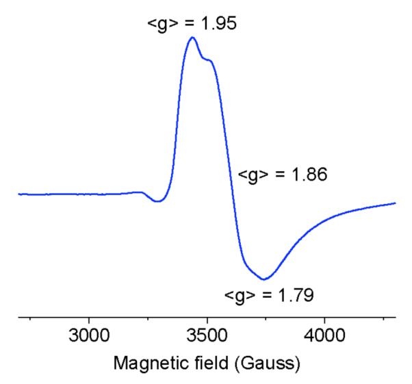
EPR spectra of 5 in MeCN at 4K. Conditions: [5] = 0.2 mM, 9.39 GHz MW frequency, 20 mW micro-wave power, 10 G modulation amplitude, and 0.2 s time constant.
Resonance Raman Spectroscopy
Resonance Raman spectra of the green species generated upon reaction of 5 with dioxygen were obtained at 110 K with 647 nm excitation. Fe—O stretching vibrations were observed at 466/476 cm−1 and 456 cm-1 for samples prepared with 16O2 and 18O2, respectively (Fig. 8). The corresponding O—O stretches for the diiron(III) peroxo complex occur near 895 cm−1 for 16O2 and can be observed near 845 cm−1 and 18O2 despite its overlap with a strong DMF solvent vibration (Fig. 8). These vibrational frequencies match our previous characterization of peroxo complexes using the same ligand platform.56 There is no 16/18O-sensitive mode in the 1050-1250 cm−1 region where ν(O—O) of Fe(III)-superoxo species are expected. The RR data thus support the assignment of the green species as a diiron(III) peroxo complex formed by intermolecular electron transfer.
Figure 8.
Resonance Raman spectra of an oxygenated DMF solution of 5 at 110 K with a 647 nm excitation.
Concluding Remarks for Reaction of 5 with Dioxygen
From the electronic absorption, Resonance Raman, and Mössbauer spectroscopic results, together with electrochemistry, it can be concluded that 5 reacts very rapidly with oxygen to form a diiron(III) superoxo complex. This putative superoxo species immediately reacts with 5 present in solution to form the green colored diiron(III) peroxo compound and a diiron(III) complex that could be 12, or at least similar to 12, because 12 was isolated by ‘water assisted’ oxidation of 5. A notable feature of 12 is that the bridging carboxylate is lost. Loss of carboxylates upon formation of diiron(III) peroxo compounds in the H-N-Et-HPTB ligand platform has precedence,35 the reasons for which have been recently explained.38 This assumption is supported by the appearance of a high spin Fe(III) site at δ = 0.40 mm/s as discussed for the reaction of 5 with O2 (Fig. 4) in the Mossbauer section. With time, the diiron(III) peroxo compound changes or combines with itself or with the other diiron(III) species to yield more stable di- or polynuclear iron(III) compound/compounds similar to 8 or 9. A reasonable description for the decomposition of related peroxo compounds to form polyiron(III) compounds can be found elsewhere.37
SUMMARY
A new diiron(II) system, [Fe2(N-Et-HPTB)(DMF)4](BF4)3 (1), has been developed that can be used as a starting material for the synthesis of carboxylate bridged diiron complexes. Addition of dioxygen to 1 leads to the formation of a highly unstable peroxo species, and its fast decomposition to polyiron complexes is described. Controlled one electron oxidation of 1 (or 3) generates the mixed valent diiron(II,III) compound 5, which has been isolated and characterized. Compound 5 features a diiron core doubly bridged by a carboxylate and a ligand-derived alkoxo group. Such a compound can be considered a resonable model for diiron(II,III) centers in O2-activating enzymes such as myo-inositol oxygenase. Reversible dioxygen reactivity of this diiron(II,III) species (5), leading to the formation of a diiron(III) peroxo compound, is described for the first time. The description of such fascinating reactivity in this report should stimulate further investigation using related diiron(II,III) compounds in different ligand environments.
Supplementary Material
Scheme 2.
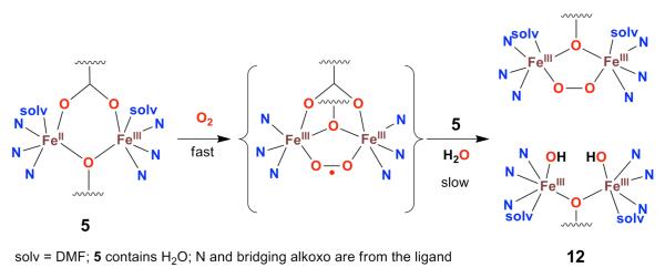
Schematic depiction of the reaction of 5 with O2.
ACKNOWLEDGMENT
This work was supported by grant GM 032134 from the National Institute of General Medical Sciences. U.-P.A. thanks the Alexander-von-Humboldt Foundation for a postdoctoral fellowship. The authors acknowledge Ms. A. D. Liang for help in collecting EPR data.
Footnotes
Supporting Information. X-ray crystallographic data for compounds 1-12 in CIF format, selected bond lengths and angles, room temperature Mössbauer spectroscopic data of 5, EPR spectra of 5 in DMF/MeCN (1:1), electronic absorption spectroscopic signatures of selected compounds and monitoring for reaction of 5 with O2. This material is available free of charge via the Internet at http://pubs.acs.org.
References
- (1).Merkx M, Kopp DA, Sazinsky MH, Blazyk JL, Muller J, Lippard SJ. Angew. Chem. Int. Ed. 2001;40:2782–2807. doi: 10.1002/1521-3773(20010803)40:15<2782::AID-ANIE2782>3.0.CO;2-P. [DOI] [PubMed] [Google Scholar]
- (2).Feig AL, Lippard SJ. Chem. Rev. 1994;94:759–805. [Google Scholar]
- (3).Lippard SJ. Philos. Trans. R. Soc. A-Math. Phys. Eng. Sci. 2005;363:861–877. doi: 10.1098/rsta.2004.1532. [DOI] [PubMed] [Google Scholar]
- (4).Wallar BJ, Lipscomb JD. Chem. Rev. 1996;96:2625–2657. doi: 10.1021/cr9500489. [DOI] [PubMed] [Google Scholar]
- (5).Rosenzweig AC, Nordlund P, Takahara PM, Frederick CA, Lippard SJ. Chem. Biol. 1995;2:409–418. [PubMed] [Google Scholar]
- (6).Rosenzweig AC, Frederick CA, Lippard SJ, Nordlund P. Nature. 1993;366:537–543. doi: 10.1038/366537a0. [DOI] [PubMed] [Google Scholar]
- (7).Rosenzweig AC, Lippard SJ. Acc. Chem. Res. 1994;27:229–236. [Google Scholar]
- (8).Tinberg CE, Lippard SJ. Acc. Chem. Res. 2011;44:280–288. doi: 10.1021/ar1001473. [DOI] [PMC free article] [PubMed] [Google Scholar]
- (9).Tshuva EY, Lippard SJ. Chem. Rev. 2004;104:987–1011. doi: 10.1021/cr020622y. [DOI] [PubMed] [Google Scholar]
- (10).Do LH, Lippard SJ. J. Inorg. Biochem. 2011;105:1774–1785. doi: 10.1016/j.jinorgbio.2011.08.025. [DOI] [PMC free article] [PubMed] [Google Scholar]
- (11).Friedle S, Reisner E, Lippard SJ. Chem. Soc. Rev. 2010;39:2768–2779. doi: 10.1039/c003079c. [DOI] [PMC free article] [PubMed] [Google Scholar]
- (12).Tolman WB, Que JL. J. Chem. Soc., Dalton Trans. 2002:653–660. [Google Scholar]
- (13).Que JL. J. Chem. Soc., Dalton Trans. 1997:3933–3940. [Google Scholar]
- (14).Que L, Dong Y. Acc. Chem. Res. 1996;29:190–196. [Google Scholar]
- (15).Sugimoto H, Nagayama T, Maruyama S, Fujinami S, Yasuda Y, Suzuki M, Uehara A. Bull. Chem. Soc. Jpn. 1998;71:2267–2279. [Google Scholar]
- (16).Suzuki M. Pure Appl. Chem. 1998;70:955–960. [Google Scholar]
- (17).Edmondson DE, Huynh BH. Inorg. Chim. Acta. 1996;252:399–404. [Google Scholar]
- (18).Kurtz DM. J. Biol. Inorg. Chem. 1997;2:159–167. [Google Scholar]
- (19).Brown PM, Caradoc-Davies TT, Dickson JMJ, Cooper GJS, Loomes KM, Baker EN. Proc. Natl. Acad. Sci. USA. 2006;103:15032–15037. doi: 10.1073/pnas.0605143103. [DOI] [PMC free article] [PubMed] [Google Scholar]
- (20).Bollinger JM, Diao Y, Matthews ML, Xing G, Krebs C. Dalton Trans. 2009:905–914. doi: 10.1039/b811885j. [DOI] [PMC free article] [PubMed] [Google Scholar]
- (21).Charalampous FC. J. Biol. Chem. 1959;234:220–227. [PubMed] [Google Scholar]
- (22).Charalampous FC, Lyras C. J. Biol. Chem. 1957;228:1–13. [PubMed] [Google Scholar]
- (23).Moskala R, Reddy CC, Minard RD, Hamilton GA. Biochem. Biophys. Res. Commun. 1981;99:107–113. doi: 10.1016/0006-291x(81)91719-8. [DOI] [PubMed] [Google Scholar]
- (24).Hartman JAR, Rardin RL, Chaudhuri P, Pohl K, Wieghardt K, Nuber B, Weiss J, Papaefthymiou GC, Frankel RB, Lippard SJ. J. Am. Chem. Soc. 1987;109:7387–7396. [Google Scholar]
- (25).Borovik AS, Que L., Jr. J. Am. Chem. Soc. 1988;110:2345–2347. [Google Scholar]
- (26).Borovik AS, Papaefthymiou V, Taylor LF, Anderson OP, Que L., Jr. J. Am. Chem. Soc. 1989;111:6183–6195. [Google Scholar]
- (27).Mashuta MS, Webb RJ, Oberhausen KJ, Richardson JF, Buchanan RM, Hendrickson DN. J. Am. Chem. Soc. 1989;111:2745–2746. [Google Scholar]
- (28).Suzuki M, Uehara A, Oshio H, Endo K, Yanaga M, Kida S, Saito K. Bull. Chem. Soc. Jpn. 1987;60:3547–3555. [Google Scholar]
- (29).Borovik AS, Murch BP, Que L, Jr., Papaefthymiou V, Munck E. J. Am. Chem. Soc. 1987;109:7190–7191. [Google Scholar]
- (30).Payne SC, Hagen KS. J. Am. Chem. Soc. 2000;122:6399–6410. [Google Scholar]
- (31).Li F, Chakrabarti M, Dong Y, Kauffmann K, Bominaar EL, Münck E, Que L., Jr. Inorg. Chem. 2012;51:2917–2929. doi: 10.1021/ic2021726. [DOI] [PMC free article] [PubMed] [Google Scholar]
- (32).Do LH, Lippard SJ. J. Am. Chem. Soc. 2011;133:10568–10581. doi: 10.1021/ja2021312. [DOI] [PMC free article] [PubMed] [Google Scholar]
- (33).McKee V, Zvagulis M, Dagdigian JV, Patch MG, Reed CA. J. Am. Chem. Soc. 1984;106:4765–4772. [Google Scholar]
- (34).Dong Y, Menage S, Brennan BA, Elgren TE, Jang HG, Pearce LL, Que L., Jr. J. Am. Chem. Soc. 1993;115:1851–1859. [Google Scholar]
- (35).Dong Y, Yan S, Young VG, Que L., Jr. Angew. Chem. Int. Ed. 1996;35:618–620. [Google Scholar]
- (36).Feig AL, Lippard SJ. J. Am. Chem. Soc. 1994;116:8410–8411. [Google Scholar]
- (37).Feig AL, Becker M, Schindler S, van Eldik R, Lippard SJ. Inorg. Chem. 1996;35:2590–2601. doi: 10.1021/ic951242g. [DOI] [PubMed] [Google Scholar]
- (38).Frisch JR, McDonnell R, Rybak-Akimova EV, Que L., Jr. Inorg. Chem. 2013;52:2627–2636. doi: 10.1021/ic302543n. [DOI] [PMC free article] [PubMed] [Google Scholar]
- (39).Avenier F, Herrero C, Leibl W, Desbois A, Guillot R, Mahy J-P, Aukauloo A. Angew. Chem. Int. Ed. 2013;52:3634–3637. doi: 10.1002/anie.201210020. [DOI] [PubMed] [Google Scholar]
- (40).Robin MB, Day P. In: Advances in Inorganic Chemistry and Radiochemistry. Emeléus HJ, Sharpe AG, editors. Vol. 10. Academic Press; 1968. pp. 247–422. [Google Scholar]
- (41).APEX II 2009 Ed. Bruker Analytical X-ray Systems Inc.; Madison, WI: 2009. [Google Scholar]
- (42).Spek AL. J. Appl. Cryst. 2003;36:7–13. [Google Scholar]
- (43).Spek AL. Acta Crystallogr. Sect. D. 2009;65:148–155. doi: 10.1107/S090744490804362X. [DOI] [PMC free article] [PubMed] [Google Scholar]
- (44).Sheldrick GM. Acta Crystallogr. Sect. A. 2008;64:112–122. doi: 10.1107/S0108767307043930. [DOI] [PubMed] [Google Scholar]
- (45).Dolomanov OV, Bourhis LJ, Gildea RJ, Howard JAK, Puschmann H. J. Appl. Crystallogr. 2009;42:339–341. doi: 10.1107/S0021889811041161. [DOI] [PMC free article] [PubMed] [Google Scholar]
- (46).Farrugia LJ. J. Appl. Cryst. 1997;30:565. [Google Scholar]
- (47).Farrugia LJ. J. Appl. Cryst. 2012;45:849–854. [Google Scholar]
- (48).Do LH, Xue G, Que L, Jr., Lippard SJ. Inorg. Chem. 2012;51:2393–2402. doi: 10.1021/ic202379b. [DOI] [PMC free article] [PubMed] [Google Scholar]
- (49).Connelly NG, Geiger WE. Chem. Rev. 1996;96:877–910. doi: 10.1021/cr940053x. [DOI] [PubMed] [Google Scholar]
- (50).Stiddard MHB, Townsend RE. J. Chem. Soc. A. Inorg. Phys. Theo. 1969:2355–2357. [Google Scholar]
- (51).Greenwood NN, Gibb TC. Mössbauer Spectroscopy. Chapmanand Hall; London: 1971. pp. 113–168. [Google Scholar]
- (52).Lang G, Marshall W. Proc. Phys. Soc. 1966;87:3–34. [Google Scholar]
- (53).Ookubo T, Sugimoto H, Nagayama T, Masuda H, Sato T, Tanaka K, Maeda Y, Okawa H, Hayashi Y, Uehara A, Suzuki M. J. Am. Chem. Soc. 1996;118:701–702. [Google Scholar]
- (54).Kim K, Lippard SJ. J. Am. Chem. Soc. 1996;118:4914–4915. [Google Scholar]
- (55).Bertrand P, Guigliarelli B, More C. New J. Chem. 1991;15:445–454. [Google Scholar]
- (56).Do LH, Hayashi T, Moënne-Loccoz P, Lippard SJ. J. Am. Chem. Soc. 2010;132:1273–1275. doi: 10.1021/ja909718f. [DOI] [PMC free article] [PubMed] [Google Scholar]
Associated Data
This section collects any data citations, data availability statements, or supplementary materials included in this article.


