Abstract
Surgical repair of the mitral valve is a difficult procedure that is often avoided in favor of less effective valve replacement because of the associated technical challenges facing non-expert surgeons. In the interest of increasing the rate of valve repair, an accurate, interactive surgical simulator for mitral valve repair was developed. With a haptic interface, users can interact with a mechanical model during simulation to aid in the development of a surgical plan and then virtually implement the procedure to assess its efficacy. Sub-millimeter accuracy was achieved in a validation study, and the system was successfully used by a cardiac surgeon to repair three virtual pathological valves.
I. INTRODUCTION
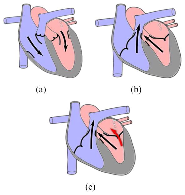
The mitral valve is one of the four valves of the human heart and separates the left atrium from the left ventricle. In a properly functioning heart, oxygenated blood flows from the left atrium into the left ventricle with the mitral valve serving as a check valve preventing backflow (Fig. 1(a) and 1(b)). Because of the large pressure gradient between the two chambers, the mitral valve is the cardiac valve most prone to disease [1]. In these pathological cases, blood often flows back across the valve (Fig. 1(c)) placing an increased workload on the heart and potentially leading to heart failure if left untreated.
Fig. 1.
Blood flow in the human heart. (a) Ventricular filling. (b) Ventricular ejection. (c) Mitral regurgitation (red arrow).
Surgical intervention is often the only course of treatment and can consist of valve repair or valve replacement. While valve repair has been shown to produce improved clinical results in terms of survival and longevity [2]–[4], the rate of valve replacement is still high as general cardiac surgeons often do not possess the experience required to accurately predict the closed valve shape post-modification [5]. This difficulty is only exacerbated by the potential for cognitive impairment from extended time intraoperatively on heart-lung bypass, making surgeon efficiency imperative [6]. A surgical planning system for mitral valve repair could alleviate these issues and increase the rate of valve repair thereby improving clinical outcomes.
Because of the complexities associated with the valve’s physiology and repair, significant efforts have been undertaken in the field of mitral valve simulation [7]–[9]. These models tend to be computationally complex, resulting in simulation times too long for pre- or intraoperative planning. In addition, most previous models used generic valve structures, making surgical planning difficult if not impossible. Recently, Hammer et al. have developed a mass-spring model of the mitral valve with clinically feasible simulation times of roughly 30 seconds and patient-specific imaging using micro-CT [10], [11]. While this work improved upon previous models, it still does not run at sufficient speeds to permit real-time user-model interaction, and without a user interface, valve modification is nearly impossible for those unfamiliar with the intricate details of the underlying model.
To address the continuing insufficiencies found in literature, we have developed a surgical planning system for mitral valve repair. Similar to [10], [11], the planning system simulates static loading of the valve, which is the test used intraoperatively to assess a valve’s competency. The valve is loaded with peak systolic pressure as it provides the greatest mechanical challenge and therefore presents the greatest potential for leakage. Using a medical image as input, the system produces a mass-spring model of the valve with which the user can interact, analyze, and then perform virtual surgery. Because real-time interactivity is essential to maximize surgeon utility, the system provides a haptic interface with force feedback and a mechanical model that enables real-time calculation of physically realistic results. A validation study then examines both the model’s accuracy and the ability of a cardiac surgeon unfamiliar with the system to virtually repair three pathological valves.
II. BACKGROUND
The mitral valve consists of three primary anatomical structures: the anterior and posterior leaflets, the mitral annulus, and the chordae tendineae (Fig. 2). The mitral leaflets are irregular, membranous flaps of tissues which attach to the mitral annulus, a fibrous ring within the cardiac wall. The motion of the leaflets is restricted by the chordae tendineae, cord-like structures with complex branching schemes, which attach at one end to the leaflets and at the other to one of the two papillary muscles of the left ventricle.
Fig. 2.
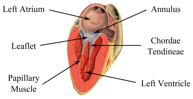
The anatomy of the mitral valve (Image source: Patrick J. Lynch, medical illustrator, C. Carl Jaffe, MD, cardiologist).
Once the left ventricle has been filled with oxygenated blood, ventricular contraction creates a pressure gradient across the valve pushing the leaflets together creating a seal. The motion of the leaflets is restricted by their mutual collision and the tethering of the chordae. If any of the valve’s three components have been damaged, the seal can be broken, and mitral regurgitation (backflow) can result. Thus, mitral valve repair targets these structures and attempts to remove any abnormalities that may exist.
III. SYSTEM DESIGN
A. Overview
The proposed simulator required a highly interdisciplinary effort with components drawn from the fields of medical imaging, image processing, mechanical modeling, and haptic interfaces (Fig. 3). An input 3D medical image is segmented and meshed. This mesh is then passed to a mechanical modeling unit which calculates the shape of the valve leaflets based on internal forces resulting from tissue deformation and external forces imposed by both the user and virtual valve pressurization. A user interface visually renders the valve and allows for haptic interaction via pushing and pulling of the tissue. In addition, the interface provides the user with the ability to perform virtual surgery on the valve and observe the results both visually and haptically. The user can continue to modify the valve until a desired surgical outcome is reached at which point the surgical plan can be recorded and implemented.
Fig. 3.

A system diagram of the surgical planning system described in this work.
B. Imaging
To maximize clinical relevancy and usefulness, the simulator’s input model would ideally be generated from readily available clinical images. Given the pervasiveness of diagnostic echocardiography, 3D ultrasound (3DUS) would thus be the imaging modality of choice. However, this presents many challenges. 3DUS images typically contain large amounts of noise and relatively poor resolution (Fig. 4(a)). As a result, segmenting the valve and its underlying structures is difficult as many of its features are at or below the resolution of the image. Nevertheless, while progress has been made delineating the larger mitral annulus and leaflets [8], [12]–[14], segmentation of the thin chordae has proven more challenging.
Fig. 4.
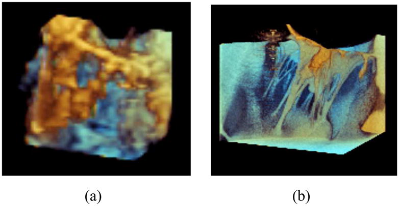
A mitral valve imaged using a (a) Philips iE33 3DUS system and (b) Siemens microCAT micro-CT system.
Given that accurate simulations of a patient’s mitral valve require accurate chordae structures [11], micro-CT (microCAT, Siemens, Erlangen, Germany) was used for its increased resolution and lower noise. Fig. 4(b) is a micro-CT image of the same valve from a similar viewing angle. Unlike the 3DUS image, the micro-CT image allows for the chordal structure to easily be delineated. It should be noted that micro-CT images of the heart are not clinically feasible as the heart must be explanted for imaging. Here micro-CT serves as input for model and simulator development until ultrasound-based methods are capable of generating a full valve reconstruction.
Using micro-CT, images are taken of the statically loaded valve and open, relaxed valve. The chordal lengths and movement of the mitral annulus and papillary muscles are recorded from the image of the closed valve. A fine triangular mesh is then fit to the surface of the open valve using Delaunay triangulation, and each chordal branch is replaced with a linear segment.
C. Valve Modeling and Simulation
As the primary goal is to produce an interactive model of the valve, computational speed must be of the utmost concern to ensure the necessary 1kHz update rate required for haptic interaction. Thus, a mass-spring model is implemented in lieu of a finite element model. To further improve computational performance, the triangulated mesh is downsampled using an interative process of edge collapse and mesh relaxation [15]. While this coarsens the mesh, it has been shown to have minimal impact on the accuracy of the final shape of the valve in mass-spring valve models [11].
To produce the mass-spring model, the edges of the triangular mesh of the open valve were taken to be the spring rest lengths. A bilinear stress-strain curve (Fig. 5) was developed to approximate the leaflet tissue model found in [16]. The curve consists of a highly distensible region of low modulus prior to a critical strain of 0.25. It is followed by a significantly stiffer post-transition region. Spring stiffness values were then computed using methods found in [17]. An assumed uniform leaflet thickness of 1mm was chosen. Chordae resting lengths were approximated by their final lengths in the closed valve as the modulus of the chordae is large enough that minimal elongation occurs under physiological load [7]. The resulting chordae spring stiffness were computed by treating the chordae as cylindrical rods with a uniform 1mm diameter.
Fig. 5.
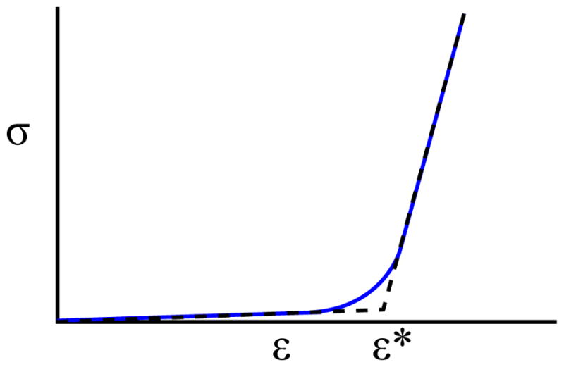
The stress-strain curve of leaflet tisue [16] (blue) and its bilinear approximation (dashed black).
Nodal masses were calculated by evenly distributing the mass of each connected face and chord. Due to the fibrous nature of the mitral annulus and the strength of the papillary muscles, these nodes were treated as fixed boundary conditions by setting their mass to be infinite. To account for their natural displacement during static loading, upon the onset of virtual pressurization the annulus and papillary muscles are warped to their final positions found in the micro-CT image of the loaded valve. Other simulation parameters with no physical meaning such as time step size and damping were tuned for a combination of performance and stability. A summary of model parameters can be found in Table I.
TABLE I.
Mitral valve model parameters taken from literature.
| Model Parameter | Value | |
|---|---|---|
| Eleaflet, pre | 100 kPa | |
| Eleaflet, post | 6 MPa | |
| εcrit | 0.25 | |
| Leaflet Thickness | 1 mm | |
| Echordae | 40 MPa | |
| Chordae Diameter | 1 mm | |
| Tissue Density |
|
|
| Pload | 120 mmHg |
In addition to the internal forces resulting from the aforementioned mass-spring structure, a variety of external forces must also be computed. Forces from pressurization are computed on a face-by-face basis and evenly distributed to the three nodes of the face. Collision detection is performed in a two-phase process. First, a cache-friendly uniform grid is used to cull potential collisions. Then, a pairwise narrow phase algorithm is used to determine exact collisions. A nonlinear restoring force law is applied to resolve collisions. Forces are then summed on a node-by-node basis, and a symplectic Euler integrator, chosen for its combination of speed and stability, is used to advance the simulation.
D. User Interface
The user interface, which visually renders the mesh and haptic cursor location using OpenGL, is designed to facilitate user interaction with the model (Fig. 6). Using a Phantom Desktop (Sensable Technologies, Wilmington, MA), the user is capable of “feeling” the mesh when touching it and manipulating any node of the mesh. When the user grabs the tissue, which is performed by clicking a button on the stylus, a stiff spring-damper system is engaged between the proxy’s location and the selected node [18]. This allows for precise grasping and is more stable than fixing the node to the proxy’s current position. The force associated with this spring-damper pair is then added to the external forces computed by the model. In addition, the computed force is scaled and transformed into workspace coordinates and provided to the user via the haptic device.
Fig. 6.
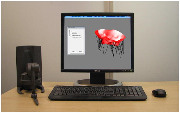
The user interface for simulated valve closure and modification.
The user also has the ability to push against tissue using the haptic stylus. This differs from grasping the tissue in that the stylus is permitted to slide along the tissue instead of dragging the current node along with it. Although potentially useful when analyzing the valve, such interactions can become awkward when performing virtual surgery, and as a result, the user can disable this feature.
The ability to virtually interact with the valve permits a greater level of valve analysis than visualization alone can provide. For instance, by pulling apart the coapted leaflets, the surgeon can determine the precise amount of leaflet coaptation, a safety measure against valve leakage. By separating the two leaflets during pressurization, the user can also isolate the chordal structures and better determine the amount of support the chordae are currently providing. Restricted leaflet motion would hint at tethering from chordae calcification, while leaflet billowing could imply elongated chordae. This additional information would assist the surgeon in planning the valve repair.
With the knowledge gained from analyzing the valve, the surgeon, through the user interface, can perform virtual surgery using common operations in mitral valve repair. These operations can be classified into two categories: mitral annuloplasty and chordal operations. Annuloplasty, the insertion of a rigid or semi-rigid ring which attaches to the mitral annulus, is used to treat cases of annular dilation. If a virtual annuloplasty is performed, a rigid ring is inserted, and the annulus nodes are warped onto the ring. Given the rigidity of the ring, the annular nodes are fixed in these positions regardless of the presence of static pressure loading.
Four typical surgical chordal operations were developed: chordal length adjustment, chordal removal, chordal addition, and chordal transfer [19]. In a chordal length adjustment, the user selects the desired chord using the haptic stylus. The user can then adjust the chordal length by either inputting a new length manually or dragging the leaflet node to the desired position. Chordal removal is performed similarly with the initial selection of a chord followed by a confirmation of the user’s desire for removal. In chordal addition, the user selects two nodes, one on a papillary muscle and one elsewhere, and a chord of user-specified length is added connecting the two. Finally, chordal transfer is performed by selecting a given chord, selecting one of chord’s endpoints, and moving it elsewhere in the valve.
Since the operations are performed in silico, it is also possible to provide features that are not physically feasible in an operating room. For instance, improved visualization can be achieved by moving the virtual camera to examine different regions of the valve. This lies in stark contrast to the limited field of view surgeons traditionally face when performing valve repair. In addition, for an inexperienced user it is possible that unacceptably large stresses and strains may be applied to the chordae after a poor surgical repair leading to questionable long-term reliability. As a result, the user has the option to render chordal strains either visually by highlighting the high strain chordae or haptically by selecting a chord and feeling the force it is imparting.
To enable and encourage experimentation with the system, the user is given the ability to undo and redo previously performed operations. The valve’s current state can also be saved in an extended .OBJ file format which can be reloaded into the simulator at a later time or into an alternate software package for improved rendering. Finally, the proposed surgical plan can be logged to file for future reference.
IV. VALIDATION
A. Overview
In order to demonstrate the potential usefulness of the surgical planning system, two primary components required validation — the underlying valve simulation model and the ability for a user to easily interact with said model. Two studies were conducted to assess the ability of the system to achieve these aims.
B. Model Validation
1) Methods
To test the model accuracy, the freshly excised heart of a 30–40kg female Yorkshire pig was imaged in three states — flaccid, statically loaded through the aorta using 120 mmHg of air, and again loaded under similar conditions with a primary chord attached to the P2 scallop of the posterior leaflet shortened to just before leakage. These images were provided to the simulation system as input. A valve model was created containing roughly 425 vertices, 625 faces, and 80 chordae.
The original, unmodified model was first simulated to closure, and its final shape was recorded. The original model, in its unpressurized state, was then modified in the surgical planning system to reflect the changes made to the excised valve. This new, modified model was simulated to closure, and its final shape was also recorded. The simulated closed valves were then registered to their corresponding CT images, and each pair was compared.
2) Results
Using a computer with a 2.67GHz Intel i7 CPU and 6GB of RAM, valve closure was simulated in less than one second, and individual time steps were computed at 1kHz allowing for smooth haptic interaction with the model. While the precise amount of time spent performing collision detection varied with valve geometry, it always proved to be the most costly operation.
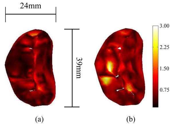
Simulation of the unmodified model resulted in a root-mean-square error of 0.5mm and a maximum error of 2.1mm. Conversely, simulation of the modified valve resulted in a root-mean-square error of 0.7mm and maximum error of 2.9mm (Fig. 7).
Fig. 7.
The error between the simulated closed valve and imaged valve, shown via colormap, both (a) pre-surgical modification and (b) post modification. Errors are in millimeters.
C. User Validation
1) Methods
The usability of the interface was examined by presenting the planning system to a cardiac surgeon with no previous experience with the simulator. After a brief training session of roughly 10 minutes, the surgeon was sequentially presented with three regurgitant, pathological valves to repair. Each valve was derived from an imaged, healthy valve with artificial pathologies generated using the planning system. The modifications made are described below; all resulted in leaking valves.
Valve 1: Annulus dilated 15%, chord elongated 25%.
Valve 2: Chord shortened 30%.
Valve 3: Annulus dilated 10%, chord shortened 33%.
The surgeon was then given the opportunity to devise a surgical plan using the simulation system and all of its features. Upon deciding on and recording a final surgical plan, the plan was implemented using the system, and the valve was simulated to closure. The final valve shape was recorded and compared to both the pathological valve and original, healthy valve with the presence, or lack thereof, of regurgitation noted. The surgical plan was also compared to the modifications made in creating the pathology.
2) Results
The details of the final surgical plan for each pathologic valve are described below.
Valve 1: Annulus reduced to 97% of its original size, additional chordae added elsewhere.
Valve 2: Annulus reduced to 95% of its original size, shortened chord removed, additional chordae added to this location to provide support.
Valve 3: Annulus reduced to 99% of its original size, shortened chordae lengthened, additional chordae added elsewhere.
Using these surgical procedures, the surgeon was able to significantly alter the leaflet shape upon pressurization and eliminate regurgitation in all three cases. Fig. 8 shows, via a central cross section, an example of such changes as seen in the third valve.
Fig. 8.
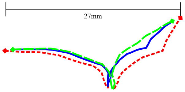
Central cross sections of the two leaflets of the original healthy valve (solid blue), pathological valve (short-dashed red), and repaired valve (long-dashed green). Leaflet intersection with the annulus is denoted by diamond markers. Pairwise root-mean-square differences were 1.3mm (healthy-pathological), 0.5mm (healthy-repaired), and 1.7mm (repaired-pathological).
V. DISCUSSION
The primary aim of this work was to demonstrate the feasability of a clinically viable, interactive surgical planner capable of accurately assessing patient-specific valve competency. In order for such a system to be useful to a surgeon, a sophisticated user interface is essential, including physically plausible real-time interaction with haptic feedback. However, to attain this real-time interactivity and to enable fast simulation times, design tradeoffs had to be made to improve the speed of model simulation.
Computational burdens were reduced by choosing to model only the static loading of the valve. While static loading is not the process the valve undergoes during the cardiac cycle, it is used intraoperatively to test valve sufficiency. Further, since loading was conducted at peak systolic pressure, it simulates the greatest mechanical challenge to the valve thus providing a worst-case scenario in which to test for regurgitation. Static loading can therefore be taken as a reasonable metric of the quality of valve function. By assuming quasi-static conditions under this peak load, we were able to neglect the complex fluid-structure interactions that would have substantially increased computational burden.
Further improving the speed of simulation was the implementation of a mass-spring model. While finite element models are the de-facto standard in terms of accuracy, they are also more computationally burdensome than their mass-spring approximations; in fact, finite element membrane models are typically an order of magnitude slower [20]–[22]. Needing to maintain a 1kHz update rate, these associated costs were simply too great when using standard computer hardware.
Even with the mass-spring approximation, the subsequent coarsening of the mesh, and bilinear approximation to the stress-strain curve, sub-millimeter root-mean-square accuracy was still achieved in the static loading simulation. While further validation is needed to definitively conclude the accuracy of the simulator’s predictions post-surgical repair, initial results are promising.
The stability of these simulations is a potential source of concern. Mass-spring membrane models, often associated with cloth simulation, typically implement adaptive time-stepping implicit integration schemes to allow for large time steps while simultaneously handling the numerical stiffness of the problem in a stable manner [10], [11], [23]. However, such methods are not practical for an interactive, haptic simulation. Effective variable time-stepping would be visually noticeable to the user and would interfere with user-model interactions, making adaptive time-stepping infeasible. In addition, the inversion of the large sparse matrix necessary for implicit integration would be challenging at haptic rates, especially for a stiff problem such as the one presented here.
With the symplectic Euler integrator that is implemented, concerns regarding numerical stability arise. It was found that when a user performed extreme operations on the valve, such as reducing the size of the annulus by 75%, the system could become unstable. Even when the size of time steps was reduced by an order of magnitude (resulting in simulation times of roughly 5 seconds), it was still possible, albeit more difficult, for the user to create model instabilities. While such operations would likely not be performed by even an inexperienced surgeon, this does demonstrate that numerical stability can no longer be deemed a near certainty as is usually the case with implicit methods [24]. While this issue does present a theoretical concern, in practice it was of little importance and was never encountered unless intentionally triggered.
In addition to the planning system’s speed and accuracy, of great promise is the system’s ability to permit the easy implementation of virtual surgery. In the validation study, the surgeon was able to successfully make significant changes to the valve to restore its function (Fig. 8). In this case, the resulting root-mean square difference between the healthy and repaired valve of 0.5mm was equal to the model error found in the model validation study. Thus, the surgeon was effectively able to use the system to return the valve to its healthy state, even though the precise operations used varied slightly from those used to create the pathology.
VI. CONCLUSION
In this work, we have demonstrated that our surgical planning system for mitral valve repair is both accurate and simple enough to be effectively used with little training. The haptic interface, which allows for real-time user-valve interaction, facilitates the analysis of both the pathological valve and the proposed surgical repair. In developing the system, we have made progress towards ameliorating some of the difficulties associated with this complex surgical procedure — namely, helping the surgeon to determine the structural modification to the valve apparatus that results in effective repair without extending the time the patient remains on heart-lung bypass. In a further extension of this work, we are investigating the implementation of the preoperative repair plan with a surgical robot to lessen the great demands on surgeon dexterity. The robot controller will assist the surgeon in executing the repair through the use of motion scaling, image overlays, and virtual fixtures.
Acknowledgments
This work was supported in part by the National Science Foundation Graduate Research Fellowship Program and the U.S. National Institutes of Health under grant NIH R01 HL073647-06.
Contributor Information
Neil A. Tenenholtz, Email: ntenenh@seas.harvard.edu, Harvard School of Engineering and Applied Sciences, Cambridge, MA 02138 USA
Peter E. Hammer, Harvard School of Engineering and Applied Sciences and the Department of Cardiac Surgery, Children’s Hospital Boston
Robert J. Schneider, Harvard School of Engineering and Applied Sciences
Nikolay V. Vasilyev, Department of Cardiac Surgery, Children’s Hospital Boston
Robert D. Howe, Harvard School of Engineering and Applied Sciences and the Harvard-MIT Division of Health Sciences and Technology
References
- 1.Turi ZG. Mitral valve disease. Circulation. 2004;109(6):38–41. doi: 10.1161/01.CIR.0000115202.33689.2C. [DOI] [PubMed] [Google Scholar]
- 2.Goldman M, Mora F, Guarino T, Fuster V, Mindich B. Mitral valvuloplasty is superior to valve replacement for preservation of left ventricular function: An intraoperative two-dimensional echocardiography study. Journal of the American College of Cardiology. 1987;10(3):568–575. doi: 10.1016/s0735-1097(87)80199-7. [DOI] [PubMed] [Google Scholar]
- 3.Moss R, Humphries K, Gao M, Thompson C, Abel J, Fradet G, Munt B. Outcome of mitral valve repair or replacement: a comparison by propensity score analysis. Circulation. 2003;108(90101):II–90. doi: 10.1161/01.cir.0000089182.44963.bb. [DOI] [PubMed] [Google Scholar]
- 4.Tischler M, Cooper K, Rowen M, LeWinter M. Mitral valve replacement versus mitral valve repair. A Doppler and quantitative stress echocardiographic study. Circulation. 1994;89(1):132. doi: 10.1161/01.cir.89.1.132. [DOI] [PubMed] [Google Scholar]
- 5.Adams D, Anyanwu A. The cardiologist’s role in increasing the rate of mitral valve repair in degenerative disease. Current Opinion in Cardiology. 2008;23(2):105. doi: 10.1097/HCO.0b013e3282f4fe47. [DOI] [PubMed] [Google Scholar]
- 6.Ormiston J, Shah P, Tei C, Wong M. Size and motion of the mitral valve annulus in man. I. A two-dimensional echocardiographic method and findings in normal subjects. Circulation. 1981;64(1):113. doi: 10.1161/01.cir.64.1.113. [DOI] [PubMed] [Google Scholar]
- 7.Kunzelman K, Cochran R, Chuong C, Ring W, Verrier E, Eberhart R. Finite element analysis of the mitral valve. The Journal of Heart Valve Disease. 1993;2(3):326. [PubMed] [Google Scholar]
- 8.Burlina P, Sprouse C, DeMenthon D, Jorstad A, Juang R, Contijoch F, Abraham T, Yuh D, McVeigh E. Patient-specific modeling and analysis of the mitral valve using 3D-TEE. Information Processing in Computer-Assisted Interventions. 2010:135–146. [Google Scholar]
- 9.Wenk J, Zhang Z, Cheng G, Malhotra D, Acevedo-Bolton G, Burger M, Suzuki T, Saloner D, Wallace A, Guccione J. First Finite Element Model of the Left Ventricle With Mitral Valve: Insights Into Ischemic Mitral Regurgitation. The Annals of Thoracic Surgery. 2010;89(5):1546–1553. doi: 10.1016/j.athoracsur.2010.02.036. [DOI] [PMC free article] [PubMed] [Google Scholar]
- 10.Hammer P, Vasilyev N, Perrin D, Del Nido P, Howe R. Fast image-based model of mitral valve closure for surgical planning. MIDAS Journal, Computational Biomechanics for Medicine (MICCAI 2008 Workshop) 2008:15–26. [Google Scholar]
- 11.Hammer P, del Nido P, Howe R. Anisotropic mass-spring method accurately simulates mitral valve closure from image-based models. Functional Imaging and Modeling of the Heart. 2011 [Google Scholar]
- 12.Voigt I, Ionasec R, Georgescu B, Houle H, Huber M, Hornegger J, Comaniciu D. Model-driven physiological assessment of the mitral valve from 4d tee. Proc SPIE Medical Imaging. 2009 [Google Scholar]
- 13.Wolf I, Hastenteufel M, De iSmone R, Vahl C, Hagl S, Meinzer H. Computers in Cardiology 2001. IEEE; 2001. Three-dimensional annulus segmentation and hybrid visualisation in echocardiography; pp. 105–108. [Google Scholar]
- 14.Schneider R, Perrin D, Vasilyev N, Marx G, del Nido P, Howe R. Mitral Annulus Segmentation From 3D Ultrasound Using Graph Cuts. Medical Imaging, IEEE Transactions on. 2010;29(9):1676–1687. doi: 10.1109/TMI.2010.2050595. [DOI] [PMC free article] [PubMed] [Google Scholar]
- 15.Persson P, Strang G. A simple mesh generator in MATLAB. SIAM review. 2004;46(2):329–345. [Google Scholar]
- 16.May-Newman K, Yin F. Biaxial mechanical behavior of excised porcine mitral valve leaflets. American Journal of Physiology-Heart and Circulatory Physiology. 1995;269(4):H1319. doi: 10.1152/ajpheart.1995.269.4.H1319. [DOI] [PubMed] [Google Scholar]
- 17.Gelder A Van. Approximate simulation of elastic membranes by triangulated spring meshes. Journal of Graphics Tools. 1998;3(2):21–42. [Google Scholar]
- 18.Colgate J, Stanley M, Brown J. Issues in the haptic display of tool use. IROS; 1995. p. 3140. Published by the IEEE Computer Society. [Google Scholar]
- 19.Alan Carpentier FF, Adams David H. Carpentier’s Reconstructive Valve Surgery. Saunders Elsevier; 2010. [Google Scholar]
- 20.Ng H, Grimsdale R. Computer graphics techniques for modeling cloth. IEEE Computer Graphics and Applications. 1996:28–41. [Google Scholar]
- 21.Volino P, Magnenat-Thalmann N. Developing simulation techniques for an interactive clothing system. VSMM; 1997. p. 109. Published by the IEEE Computer Society. [Google Scholar]
- 22.Hammer P, del Nido SMSP, Howe R. Mass-spring model for simulation of heart valve tissue for mechanical behavior. Annals of Biomedical Engineering. 2011:1–12. doi: 10.1007/s10439-011-0278-5. [DOI] [PMC free article] [PubMed] [Google Scholar]
- 23.Baraff D, Witkin A. Large steps in cloth simulation. Proceedings of the 25th Annual Conference on Computer Graphics and Interactive Techniques; ACM; 1998. pp. 43–54. [Google Scholar]
- 24.Press W, Teukolsky S, Vetterling W, Flannery B. Numerical Recipes: the Art of Scientific Computing. Cambridge Univ Pr; 2007. [Google Scholar]


