Abstract
In this paper, a numerical procedure for the analysis of peripheral nerve excitation through magnetic stimulation is presented and used to investigate the physical parameters influencing stimulation. The finite difference technique is used to evaluate the electric field distribution induced inside an arm by the current flowing through a coil, and a nonlinear cable model is used to describe the response of the nerve fiber to the induced electric field. The comparison among several forearm structures has evidenced that the heterogeneous non dispersive forearm model is a good reference condition. With this model, the lowest charging voltage on the stimulator capacitance, able to produce the nerve stimulation, is achieved when the coil is shifted, with respect to the nerve, of a quantity slightly lower than the coil radius but it is also possible to excite the nerve fiber by applying a shift equal to zero. The charging voltage increases when the coil radius is increased and when a three-dimensional coil geometry is considered. Moreover, this voltage is strongly dependent on the nerve position inside the forearm and on the kind of tissue surrounding the nerve.
Keywords: Admittance method, forearm model, nonlinear cable model, peripheral nerve stimulation.
INTRODUCTION
The possibility to excite peripheral nerves by magnetic stimulation (PMS) has been clinically demonstrated for the first time by Polson et al. [1]. Since then, this technique has gained a growing significance in clinical medicine, particularly in the determination of peripheral nerve conduction times [2]. Magnetic stimulation has some advantages in comparison with the conventional electrical stimulation. For example with PMS it is possible to stimulate nerves inside arms, inducing only low current densities through the skin where pain receptors are located [3]. However, some disadvantages are present too: the stimulator experimental set-up is quite expensive, the frequency of the stimulus repetition is low, and there is uncertainty regarding the exact point where stimulation takes place [2,4].
A wide literature exists about peripheral nerve magnetic stimulation. Some works considered the electromagnetic problem of evaluating the electric field and its spatial derivate induced within a tissue by currents circulating in coils of different shapes [5-15]. Other authors studied the effect of the field distribution on the excitation of nervous fibers [16-23].
The electric field inside a homogeneous cylindrical tissue induced by a circular coil was evaluated by summing the contribution arising from the vector potential (produced by the current in the coil) [5] and from the scalar potential (produced by the charges accumulated on the surface of the cylinder) [6]. In particular, Roth et al. [5] showed that the maximum electric field intensity induced on the nerve is reached when the circular coil is placed tangential to the surface of the nerve itself. The evaluation of the electric field and its spatial derivate produced in an arm by a current flowing through the wire of a circular coil was performed using elliptic integrals [7], by considering the exact solution for pseudo cylindrical structures [8], by a summation of modified Bessel functions [9, 10], by an equivalent electric network derived by Maxwell’s equations [11-13] and through a three-dimensional finite element (FEM) model [14]. D’inzeo et al. [15] have performed a comparative study between the techniques proposed in [9] and [13]. The two techniques gave results in a good agreement. The study has confirmed the usefulness of the analytical technique in the optimization of the stimulation coils and the capability of the numerical method to analyze complex geometries.
Regarding the stimulation effects of the field on the nervous fiber, the first work in this direction was presented by Mc Neal [16]. He described the behavior of a myelinated nerve, modeled with 21 nodes of Ranvier, in presence of an electrical stimulation. The stimulation took place only in the central node modeled by the Frankenauser-Huxley’s equation [17]. The author showed that the nerve can be excited when an electric field gradient is present along its axis. Basser and Roth [18] have extended Mc Neal’s work to the magnetic stimulation. The magnetic stimulation of neuronal structures of finite length with all the nodes of Ranvier active was analyzed [19, 20] using a new model for the Ranvier’s node of mammalian [21]. The Authors showed that the stimulation depends on two main factors: the electric field derivative along the nerve and the electric field at the boundaries of the structure [20]. If the length of the fiber is greater than the spatial extent of the induced fields, the stimulation is only given by the electric field derivative, otherwise the electric field at the boundaries must be considered too. More recently, a commercial simulation environment called NEURON [22] has been used to investigate the magnetic stimulation of central nervous system neurons [23]. The simulations indicated that the peak amplitude of the stimulation, required for the generation of an action potential, is inversely proportional to the square of the fiber’s diameter.
All the cited works have addressed the problem of magnetic stimulation either from the source to the activating function or from the activating current pulse to the nerve excitation. No attempt has been done to integrate the electromagnetic solution with the electrophysiological one.
In this paper, the magnetic stimulation of peripheral nerves is studied, starting from the stimulator characteristics up to the dynamics of the nervous fiber excitation in order to investigate the physical mechanisms underlying the nerve excitation. In particular, the analysis will be carried out for different anatomical limb models, coil dimensions, and nerve geometries and positions.
METHODS
Model of the Forearm
For investigating the influence of the art geometry and tissue properties in PMS, various art models have been considered. All the models have been obtained using cross-sections of the right forearm of the “Visible Human Project” representing an anatomical data base in electronic format [24]. In particular, two arm geometries have been considered: the first is obtained by superimposing 59 identical layers corresponding to a forearm section at the level of the third proximal (cylindrical arm model: C-ARM) (see Fig. 1); and in the second, the real anatomical structure is obtained superimposing 59 different sections from the wrist to the third proximal (anatomical arm model: A-ARM). In both cases, a cubic cell model with a 2.5 mm side has been obtained.
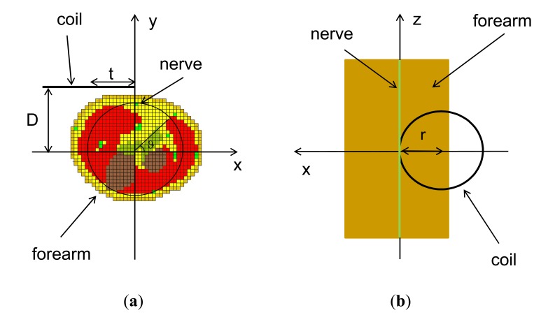
Fig. (1).
Arm-coil geometry and positioning for the stimulation of the median nerve: horizontal (a) and vertical (b) sections.
Concerning the arm tissues, an homogeneous structure (HOM), an heterogeneous structure (see Fig. 1a) whose tissues have non-dispersive properties (HET-ND) and an heterogeneous structure whose tissues have dispersive properties (HET-D) have been considered. Moreover, for comparison purposes, a semi indefinite half-space has also been taken into account. In conclusion, six models will be studied: a half space (UNBOUNDED), a cylindrical homogeneous arm (C-ARM-HOM), a cylindrical heterogeneous non dispersive arm (C-ARM-HET-ND), a cylindrical heterogeneous dispersive arm (C-ARM-HET-D), an anatomical heterogeneous non dispersive arm (A-ARM-HET-ND), and an anatomical heterogeneous dispersive arm (A-ARM-HET-D).
The conductivity and permittivity values used for the arm tissues have been taken from [25-28]. For the conductivity, the frequency dependence has been neglected while for the permittivity the frequency dependence has been taken into account by the equation: . This expression yields a good interpolation of the experimental data from [25], for frequencies from DC to about 10 MHz. The conductivity, α, and β parameter values, used in this work, are reported in Table 1. For muscle and nerve tissues, different values have been considered for the transversal and longitudinal conductivity and permittivity.
Table 1.
Conductivity and Permittivity Values of the Considered Tissues
| Tissue | Transversal Conductivity (S/m) | Permittivity | Longitudinal Conductivity (S/m) | Permittivity | ||
|---|---|---|---|---|---|---|
| a | b | a | b | |||
| Air | 0.0 | - | - | 0.0 | - | - |
| Skin | 0.0002 | 6.5 | 0.5 | 0.0002 | 6.5 | 0.5 |
| Fat | 0.02 | 6.0 | 0.5 | 0.02 | 6.0 | 0.5 |
| Muscle | 0.08 | 8.0 | 0.75 | 0.3 | 6.5 | 0.5 |
| Bone | 0.02 | 4.0 | 0.33 | 0.02 | 4.0 | 0.33 |
| Tendon | 0.4 | 4.0 | 0.33 | 0.4 | 4.0 | 0.33 |
| Nerve | 0.05 | 6.0 | 0.5 | 0.5 | 6.0 | 0.5 |
Model of the Stimulator
The stimulator has been modeled by a 40 turn circular coil with radius "r". The coil center is placed at a distance "D" from the x-axis and "t" from the y-axis (see Fig. 1).
The magnetic stimulator equivalent electric circuit is a series RLC circuit. The inductance value can be approximated using the following equation valid for a circular coil with N turns and conductor radius equal to “b” [29]:
| (1) |
The coil current is generated by the discharge of a capacitor (C = 200μF) initially charged at the voltage V0. The circuit is designed to have an over damped current behavior (). In this situation, the current has the following time behavior:
| (2) |
where:
| (3) |
In the simulations, a 40 turns coil with a radius equal to 40 mm and an inductance L=323 μH has generally been considered. The stimulator capacitance and coil resistance have been fixed to C=200 μF, and R=2.694 Ω, respectively, thus giving rise to an over damped current behavior with (=1.06. Under these conditions, all the parameters in Eq. 2 are defined except the voltage V0. Therefore, in the following study, the stimulation of the nerve membrane will be related to this parameter (threshold voltage).
Model of the Myelinic Axon
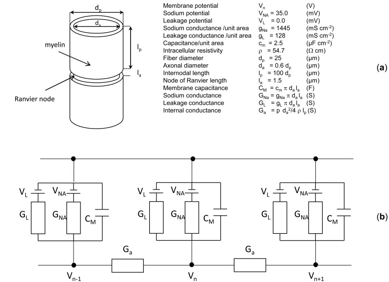
A myelinated fiber consists of a series of segments of active membrane of length "la" and diameter "da" (nodes of Ranvier), which are joined by passive segment of length "lp" and diameter "dp" covered by myelin (see Fig. 2a). The equivalent circuit for the fiber is given in Fig. (2b). The Ranvier node is modeled as proposed in [18] and the passive segments are modeled with axial conductances. The circuit parameters, with their definitions and values, are reported in the inset in Fig. (2a).
Fig. (2).
Sketch of a myelinated fiber and parameter definitions (a), equivalent circuit of the fiber (b).
By applying Kirchhoff law for the currents to the generic node “n” in Fig. (2b), the following differential equation is obtained:
| (4) |
where Δ z=lp.
Two additional differential equations with nonlinear coefficients are necessary to evaluate the activation and inactivation variables “m” and “h” [18]. For each node this set of three differential equations with appropriate initial conditions has been solved using the Runge-Kutta numerical method [30]. It can be noted that in Eq. 4 the second term inside parenthesis is proportional to the z-derivative, evaluated at each node of Ranvier, of the z-component of the electric field (). This term is responsible for the nerve excitation and it is often called “activation function” [20].
Electromagnetic Model
In order to study the EM field distribution inside the forearm, the finite difference technique has been used [13]. This method is based on the discretization of Maxwell’s equations under the hypothesis of quasi-static conditions. The region to be studied is divided in homogeneous cells of sides Δx, Δy, Δz, centered in (x,y,z). A tridimensional star of admittances (), whose values depend on the dielectric properties of the tissues, and of generators (), related to the vector potential components, is associated to each cell. As an example, the admittance and generator are given by:
| (5) |
where represents the complex conductivity at the center of the cell centered in x, and is the x-component of the vector potential on the face between the cell centered in x and x+Δx. Similar expressions stand for the other admittances and generators.
Applying Kirchhoff’s law to the nodes of the circuit, the following equation is obtained:
| (6) |
The resulting linear system of N equations in N unknowns can be solved iteratively using an over relaxation technique:
| (7) |
where Vn+1(x,y,z) and Vn (x,y,z) are the potentials at the node (x,y,z) for the iterations (n+1) and n respectively while ( is the relaxation constant whose values can range between 1 and 2. The procedure stops when an established tolerance condition is met.
For a coil with N turns and a constant current I, the vector potential in Eq. 6 can be evaluated by approximating the coil with a 64-sided polygon of length dl and summing the contributions of each side as follows:
| (8) |
where ri represents the distance between the current element dli and the point (x,y,z).
Block Scheme of the Magnetic Stimulation
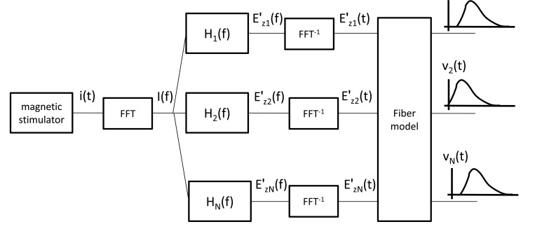
For studying the magnetic stimulation of peripheral nerves the block scheme shown in Fig. (3) has been followed.
Fig. (3).
Block scheme of the proposed magnetic stimulation procedure.
The magnetic stimulator is composed by a coil connected to a capacitor charged to a voltage (V0) of the order of some kV. The charge accumulated on the capacitor is discharged through the coil and gives rise to the current i(t). The Hn(f) functions correlate the behavior of the coil current in the frequency domain (I(f)) to the electric field derivative along the nervous fiber () in a given number (n) of nodal points (the Ranvier nodes of the myelinated fiber). These functions are evaluated by solving the electromagnetic problem with the finite difference technique. The electric field derivatives in time domain () provide the excitation for the model of the nervous fiber. Solving the nonlinear coefficients partial derivatives equations of the fiber model, the membrane potential time behavior Vn(t) in the nodal points is obtained. In the proposed procedure, the voltage V0 is set to an initial value equal to zero and then increased by 10 V steps until reaching the voltage (threshold) where the action potential is generated along the fiber.
RESULTS AND DISCUSSIONS
Influence of the Forearm Tissues and Geometry
A first set of simulations has been performed in order to evaluate the influence of the forearm tissues and geometry on the magnetic stimulation of the median nerve. In these simulations, the coil has been assumed with all the turns having the same position and radius and has been placed at a distance of 5 mm from the skin surface, while the nerve is placed 5 mm under the skin surface. Moreover, as suggested in [15], in order to optimize the stimulation the coil is shifted along the negative x-axis of the coordinate system of a quantity t=r (see Fig. 1).
By applying the previously described procedure (see Fig. 3), the threshold voltages have been evaluated for the six considered forearm models. The obtained results are shown in Table 2.
Table 2.
Voltage Threshold for the Different Forearm Models
| UNBOUNDED | C-ARM-HOM | C-ARM-HET-ND | C-ARM-HET-D | A-ARM-HET-ND | A-ARM-HET-D | |
|---|---|---|---|---|---|---|
| V0 (V) | 2850 | 3240 | 3840 | 3635 | 3795 | 3595 |
The lowest threshold value is obtained for the unbounded medium, while the highest one for the heterogeneous non dispersive cylindrical arm.
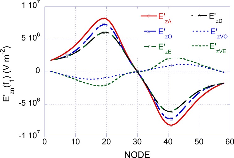
In order to understand the physical rationale at the basis of the results reported in Table 2, the electric field derivative obtained by applying to the coil a current of 1 A at the frequency f1 = 50 Hz has been evaluated as a function of the position along the fiber. The obtained results are reported in Fig. (4). Note that the function takes complex values and only the coefficient of the imaginary part is reported in the figure. It is worth noting that for all the non-dispersive forearm models, the behavior of at frequencies different from 50 Hz is similar to that reported in Fig. (4) with an amplitude scaling factor given by f/50.
Fig. (4).
Electric field derivatives, evaluated at the frequency f1=50 Hz, as a function of the position along the nerve (A= unbounded, O=homogeneous, E=heterogeneous, D=dispersive).
When considering the UNBOUNDED situation only the vector potential (related to the current in the coil by Eq. 8) contributes to the electric field derivative ( in Fig. 4). Since, in order to excite the nerve membrane, negative values of the electric field derivative are necessary (see Eq. 4), the nerve excitation starts in correspondence of the negative peak of the curve in Fig. (4) at the node 41.
By considering the cylindrical homogeneous model (C-ARM HOM), the current induced in the tissue by the magnetic field produced by the coil, flowing towards the air tissue interface, gives rise to a charge accumulation that in turns produces a scalar potential distribution and, hence an additional contribution to the electric field (EV = - (∇V). The total electric field is: E = EA + EV = -jωA - (∇V, while the activation function, that is the total electric field derivative along the nerve (z) axis is: .
For the homogeneous case, Fig. (4) shows the total field derivative and the corresponding two contributions: is the same as in the unbounded situation () while has lower amplitude and is opposite with respect to . Therefore a reduction in the absolute value of the total electric field derivative with reference to the unbounded situation is obtained that in turn gives rise to a reduction of the excitation term in Eq. 4. In conclusion it is necessary to apply higher voltage values to the capacitor of the stimulator, with respect to the unbounded situation, to give rise to the nerve excitation (see Table 2, second column).
If the heterogeneous non dispersive structure of the forearm is taken into account (C-ARM HET-ND), a further increase in the voltage can be observed (Table 2, third column). In this case, in fact, due to the anatomy considered for the forearm, which takes in to account six different tissues (see Fig. 1a), an contribution higher than in the homogeneous case is obtained (see Fig. 4): this produces a further reduction of the total electric field derivative ( in Fig. 4).
In the previous cases, the Hn(f) functions have been evaluated only at the frequency of 50 Hz and the frequency behavior has been linearly extrapolated. When the heterogeneous dispersive model is taken into account (C-ARM HET-D) the Hn(f) functions vary non-linearly with the frequency. This dependence has been evaluated by computing the Hn(f) functions at 37 frequencies chosen in the range between 50 Hz and 500 kHz (from 50 to 500 step 50; from 1.000 to 5.000 step 500; from 10.000 to 50.000 step 5.000; from 100.000 to 500.000 step 50.000; all values in Hz) and by interpolating linearly between the obtained values. The obtained are complex functions and only the imaginary part is reported in Fig. (4). In this case, a slight decrease in the voltage threshold is obtained (see Table 2 forth column).
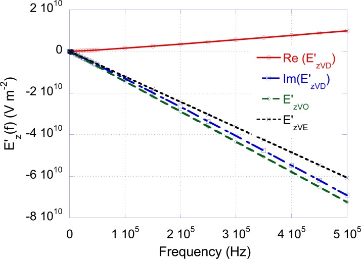
In order to understand the differences in the results obtained between the non-dispersive and dispersive situations, the frequency behavior of (real and imaginary part) together with the frequency behavior of and has been plotted in Fig. (5). The figure outlines that the imaginary part of is close to at low frequencies and tends to at high frequencies. In a qualitative way, this result can be explained observing that the introduction of the capacitors (related to the tissue permittivity) in the electric model of the forearm partially short-circuits the conductances (in particular when the frequency increases) and brings the structure towards the homogeneous situation.
Fig. (5).
Frequency behavior of the electric field derivatives (O=homogeneous, E=heterogeneous, D=dispersive).
In the anatomical models (A-ARM-HET-ND and A-ARM-HET-D), the nerve changes its coordinate in the x-y plane when varying the section along the z axis. In both cases, the computed V0 values are close to that obtained with the heterogeneous non dispersive model (see Table 2 fifth and sixth column).
In conclusion, on the basis of the performed study, the heterogeneous non dispersive model of the arm represents a good compromise between the computational time (about forty times higher for the dispersive models) and the accuracy of the results.
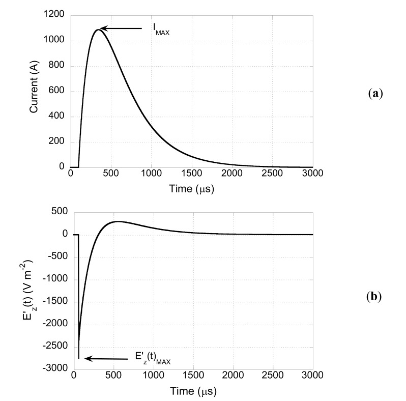
With reference to this case, Fig. (6a) shows the time behavior of the current in the coil (r=40 mm, L=323 μH, R=2.694 Ω, C=200 μF) when the threshold voltage for this configuration (3840 V) is applied. The peak value (IMAX=1068 A) is reached 149 μs after the beginning of the capacitor discharge. The obtained peak current value is compatible with specifications of commercial stimulators [31].
Fig. (6).
Time behavior of the current in the coil (a), and time behavior of the electric field derivative induced inside the tissue (b).
Using the previously described procedure (see Fig. 1), the time behavior at each node of the fiber can be evaluated. As an example, Fig. (6b) shows this behavior in correspondence of the node where the derivative has its highest value (excitation point). The curve shows a negative peak () followed by a lower positive overshoot. The time behavior is proportional to the time derivative of the coil current reported in Fig. (6a). This is due to the fact that the electric field in the tissue is related to the time derivative of the vector potential that, in turns, depends on the coil current. Concerning the amplitude, this depends on the coil current and on the spatial Ez field variations that are mainly due to the coil geometry.
Effect of the Coil Shift
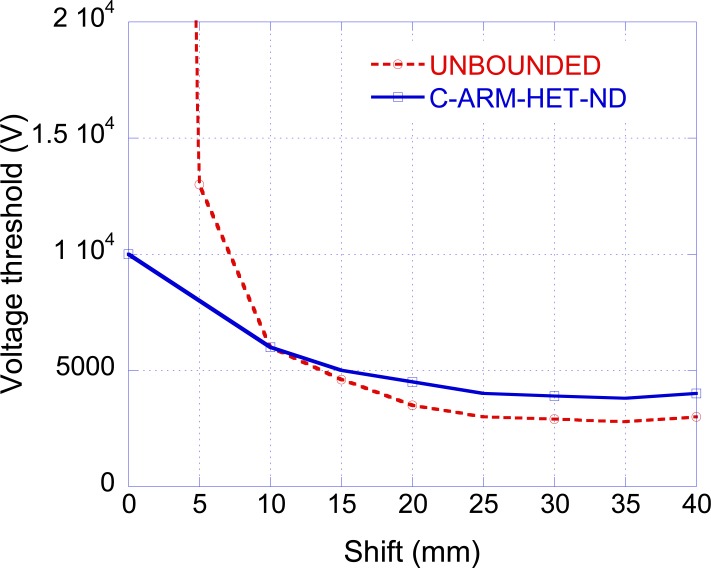
In all the previous simulations, the shift ('t' in Fig. 1) has been considered equal to the coil radius (r) since this value has been generally considered as the optimum one [18]. To verify this assumption, the voltage V0 has been evaluated as a function of the shift. Fig. (7) shows the results for the unbounded medium and for the heterogeneous non dispersive arm. From the figure, it appears that the optimal shift does not exactly correspond to the coil radius (r = 40 mm) but is slightly lower (t = 35 mm).
Fig. (7).
Voltage threshold as a function of the coil shift.
It is interesting to note that in the unbounded situation, when considering a shift equal to zero, the nerve is placed in front of the coil center and the electric field derivative at the nerve position is equal to zero, hence the threshold voltage goes to infinity. On the contrary, in the case of the heterogeneous arm, it is possible to excite a nerve fiber by applying a shift equal to zero. This result is due to the presence of the term and has also been observed experimentally [32, 33].
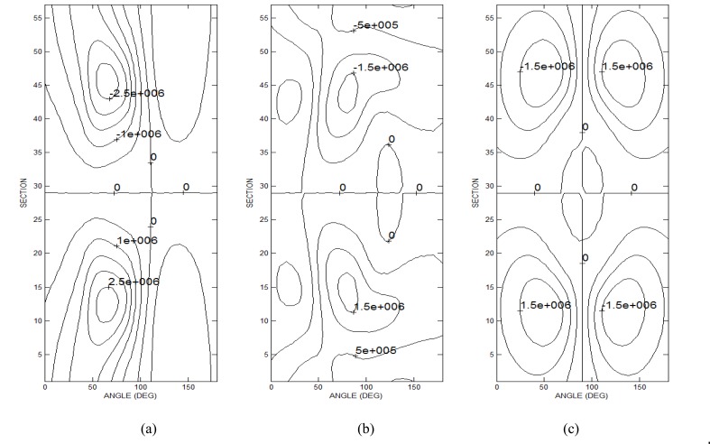
In particular, Ruohonen et al. [32] have justified the excitation of a nerve fiber, exposed to a field giving rise to , by suggesting that the electric field components perpendicular to the nerve were responsible for the nerve excitation. Kobayashi et al. [33] have presented a mathematical model based on the finite element method predicting the excitation of a nerve fiber at the center of a figure eight coil (where ) due to the presence of a tissue inhomogeneity. Our analysis confirms this last result in the case of a circular coil and in the presence of a realistic anatomical model. In order to better clarify the results obtained with the anatomical model when the coil is shifted of t = 0, the distributions of the electric field derivative have been computed, at the frequency of 50 Hz, on a semi-cylindrical surface passing through the nerve fiber. In particular are reported in Figs. (8a, 8b and 8c) respectively.
Fig. (8).
Contour plots of the electric field derivatives on a cylindrical surface containing the nerve. (a) electric field derivative (); (b) contribution due to the scalar potential (); (c) contribution due to the vector potential ().
Fig. (8a) outlines the presence of high values of in correspondence of the nerve (angle equal to 90°). Particularly in this case, only contributes to the electric field derivative (see Fig. 8b) since is null in correspondence of the nerve position (see Fig. 8c). It is worth noting that in this case the fiber excitation takes place in the upper part of the nerve where negative values of are present, while when the is the prevailing contribution the excitation takes place in the lower part of the nerve (see Fig. 4).
Effect of Coil Radius and Geometry
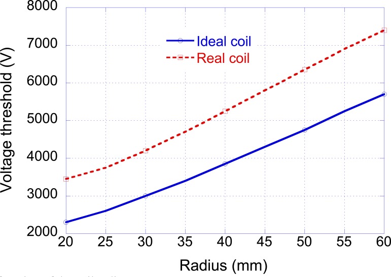
In order to evaluate the effect of the coil radius on the threshold voltage, the proposed procedure has been applied by varying the radius between 20 and 60 mm (see Fig. 9: Ideal coil). The obtained results show that by increasing the coil radius the threshold voltage increases.
Fig. (9).
Threshold voltage as a function of the coil radius.
To investigate the rationale at the basis of the obtained behavior, the heterogeneous forearm model has been considered by fixing the capacitor's voltage at the value of 3840 V and by varying the coil radius in the defined range. In this manner, the effect of the voltage applied to the stimulator is the same for all the radii and only the other stimulator parameters determine the variations in the value (see Fig. 6), that is the main factor responsible for the nerve activation.
The obtained results have shown that by increasing the coil radius both and "L" increase. This last increase determines in turn a reduction in the peak of the coil current (IMAX) (see Eq. 2) and also of its derivative. This last effect is dominant, therefore reduces when increasing the radius of the coil and hence higher voltages are necessary for inducing the nerve excitation.
With reference to the considered arm, the effect of the finite diameter of the coil wires has also been studied. As a first approximation, this problem has been addressed by considering the various turns with a different radius and at a different distance (D in Fig. 1) from the center of the reference system. In particular, a coil made of 40 turns placed on 5 layers has been considered; the wire diameter has been supposed equal to 2 mm. The obtained voltage thresholds are reported in Fig. (9) (Real coil) showing an increase in the voltage V0 with respect to the ideal situation (all the turns with the same radius and the same position) more pronounced for small radii (50% increase when r = 10 mm) than for high radii (30% increase when r = 60 mm). It is worth noting that in spite of the higher voltage necessary for nerve stimulation, the corresponding peak currents are yet achievable with commercial stimulators [31].
Effect of Nerve Geometry and Position
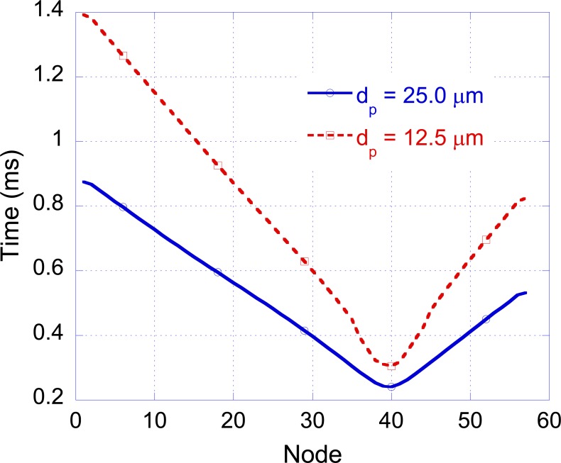
The effect of nerve geometry on magnetic stimulation has been studied by considering the C-ARM-HET-ND model excited as in the “influence of the forearm tissue and geometry” section. In particular, by using Eq. 4, the membrane voltage in correspondence of the nodes of Ranvier for various fiber diameters dp and intermodal lengths lp has been computed. Starting from the membrane voltage behaviors the activation time, defined as the time in which the action potential reaches its maximum value, has been evaluated. The plot of the activation time as a function of the position along the nerve is called activation diagram [20] and the slope of the curve gives the pulse conduction velocity. By fixing lp = 2.5 mm and reducing dp from the previously used value of 25 μm to 12.5 μm the voltage threshold changes from 3840 V to 7250 V and the conduction velocity from 69 m/s to 150 m/s, respectively (See Fig (10)). The obtained numerical results are in good agreement with experimental observations [20].
Fig. (10).
Activation diagram for dp equal to 12.5 µm and 25 µm.
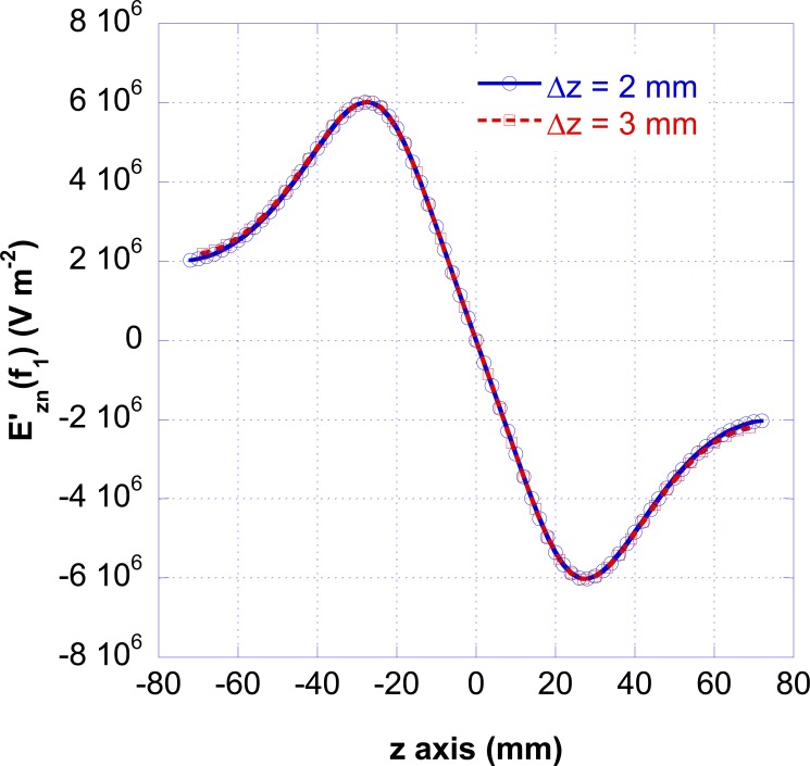
To study the influence of the intermodal distance lp = Δz, the electromagnetic simulations have been performed by leaving Δx=Δy = 2.5 mm and considering Δz=2 mm and Δz=3 mm. Fig. (11) shows the electric field derivative as a function of the position along the nerve for these two cases. The plots are identical to that computed for Δz=2 mm (see Fig. 4) but the fields derivatives are computed with a different spatial step.
Fig. (11).
Electric field derivatives, evaluated at the frequency f1=50 Hz, as a function of the position along the nerve for Δz= 2mm and Δz= 3 mm.
By solving Eq. 4 with dp = 25 μm and consideringΔz=2 mm and Δz=3 mm, the obtained voltage thresholds are 4760 V and 3220 V and the conduction velocities 126 m/s and 157 m/s, respectively. The obtained numerical results show that the threshold voltage is inversely proportional to the fiber diameter and the internodal length.
The effect of the nerve position has been investigated placing the nerve in different positions inside the heterogeneous arm. In all cases, the distance between the nerve and the skin surface and the distance between the coil and the skin surface have been fixed to the value of 5 mm. Considerable variations in V0 have been obtained for the same arm model and coil geometry. Since in all the situations, the coil nerve distance is the same, the reported variations can be due to the bend radius of the arm under the coil or to the electrical properties of the tissues surrounding the nerve.
In order to investigate the first effect, a homogeneous cylinder model of the arm has been considered and its radius has been varied from 2 to 5 cm. The coil radius has been considered equal to 40 mm. The increase of the arm radius gives rise to a reduction in the threshold voltage more relevant for higher arm radii. This result is due to a reduction in the terms, in fact by increasing the arm radius the geometry tends to the unbounded situation.
In order to investigate the effect of the tissue surrounding the nerve, the conductivity of the fat tissue surrounding the nerve has been varied by increasing and reducing its value. In particular, by doubling and halving the conductivity value, a reduction from 3840 V to 3650 V and an increase from 3840 V to 4230 V of the threshold voltage have been obtained, respectively. In conclusion, if the conductivity of the tissue surrounding the nerve increases, reduces, and increases and as a consequence, the threshold voltage decreases. The contrary happens if the conductivity decreases.
CONCLUSIONS
A model for the study of peripheral nerve excitation induced by magnetic stimulation has been proposed. With the proposed model, all the terms that contribute to the nerve excitation can be analyzed and their contribution can be quantified. Moreover, the numerical technique used for solving the EM problem presents the advantage, with respect to other techniques like FEM, to allow an easy and straightforward implementation of voxel based anatomical models and to take into account the dispersive properties of the biological tissues.
The comparison among several forearm structures has shown that the heterogeneous non dispersive forearm model is a good reference situation. The analysis performed by varying the coil position has evidenced that in the reference situation it is possible to excite a nerve fiber by applying a shift equal to zero. Moreover, higher voltage values are necessary for inducing the nerve excitation when increasing the radius of the coil and for three-dimensional coil geometries. A parametric study has evidenced that the threshold voltage is strongly dependent on the arm bending and on the nerve position inside the forearm.
The proposed procedure has a broad field of applications, for example it can be used for the study of complex coil geometries (square, double, quadruple), for the analysis of focalizing configurations, and for the study of the head magnetic stimulation by introducing a modified model of the exposed organ and of the nerve.
ACKNOWLEDGEMENTS
None declared.
PATIENTS CONSENT
No.
COMPETING INTERESTS
The authors declare that they have no competing interests.
REFERENCES
- 1.Polson MJR, Barker AT, Freeston IL. Stimulation of nerve trunks with time-varying magnetic fields. Med. Biol. Eng. Comput . 1982;20:243–244. doi: 10.1007/BF02441362. [DOI] [PubMed] [Google Scholar]
- 2.Evans BA. Magnetic stimulation of the peripheral nervous system J. Clin. Neurophysiol . 1991;8 1:77–84. doi: 10.1097/00004691-199101000-00009. [DOI] [PubMed] [Google Scholar]
- 3.Maccabee PJ, Amassian VE, Cracco RQ, Cracco JB, Eberle L, Rudell A. Stimulation of the human nervous system using the magnetic coil. J. Clin. Neurophysiol. 1991;8 1:38–55. doi: 10.1097/00004691-199101000-00006. [DOI] [PubMed] [Google Scholar]
- 4.Geddes LA. History of magnetic stimulation of the nervous system J. Clin. Neurophysiol. 1991;8 1:3–9. doi: 10.1097/00004691-199101000-00003. [DOI] [PubMed] [Google Scholar]
- 5.Roth BJ, Cohen LG, Hallet M, Friauf W, Basser PJ. A theoretical calculation of the electric field Induced by magnetic stimulation of a peripheral nerve. Muscle Nerve . 1990;13:734–741. doi: 10.1002/mus.880130812. [DOI] [PubMed] [Google Scholar]
- 6.Salinas FS, Lancaster JL, Fox PT. Detailed 3D models of the induced electric field of transcranial magnetic stimulation coils. Phys. Med. Biol. 2007;52:2879–2890. doi: 10.1088/0031-9155/52/10/016. [DOI] [PubMed] [Google Scholar]
- 7.Davey KR, Cheng CH, Epstein CM. Prediction of magnetically induced electric fields in biological tissue. IEEE Trans. Biomed. Eng. 1991;38 5:418–422. doi: 10.1109/10.81560. [DOI] [PubMed] [Google Scholar]
- 8.Ruohonen J, Ravazzani P, Grandori F. An analytical model to predict the electric field and excitation zones due to magnetic stimulation of peripheral nerves. IEEE Trans. Biomed. Eng. 1995;42:158–161. doi: 10.1109/10.341828. [DOI] [PubMed] [Google Scholar]
- 9.Esselle KP, Stuchly MA. Quasi static electric field in a cylindrical volume conductor induced by external coils. IEEE Trans. Biomed. Eng. 1994;412:151–158. doi: 10.1109/10.284926. [DOI] [PubMed] [Google Scholar]
- 10.Esselle KP, Stuchly MA. Cilindrical tissue model for magnetic field stimulation of neurons: effects of coil geometry IEEE Trans. Biomed. Eng. 1995;429:934–941. doi: 10.1109/10.412660. [DOI] [PubMed] [Google Scholar]
- 11.Cerri G, DeLeo R, Moglie F, Schiavoni A. An accurate 3-D model for magnetic stimulation of the brain cortex. J. Med. Eng. Tech. 1995;19:7–16. doi: 10.3109/03091909509030264. [DOI] [PubMed] [Google Scholar]
- 12.DeLeo R, Cerri G, Balducci D, Moglie F, Scarpino O, Guidi M. Computer modelling of brain cortex excitation by magnetic field pulses. J. Med. Eng. Tech. . 1992;16:149–156. doi: 10.3109/03091909209030218. [DOI] [PubMed] [Google Scholar]
- 13.D’Inzeo G, Giacomozzi C, Pisa S. Analysis of the stimulation of a nerve fiber surrounded by an inhomogeneous anisotropic and dispersive tissue. ACES J. 1992;72:179–190. [Google Scholar]
- 14.Krasteva VTZ, Papazov SP, Daskalov IK. Peripheral nerve magnetic stimulation: influence of tissue non-homogeneity. Biomed. Eng. OnLine. . 2003;2 doi: 10.1186/1475-925X-2-19. [DOI] [PMC free article] [PubMed] [Google Scholar]
- 15.D'Inzeo G, Esselle KP, Pisa S, Stuchly MA. Comparison of homogeneous and heterogeneous tissue models for coil optimization in neural stimulation. Radio Sci. 1995;30:245–253. [Google Scholar]
- 16.McNeal DR. Analysis of a model for excitation of myelinated nerve. IEEE Trans Biomed Eng. 1976;23:329–337. doi: 10.1109/tbme.1976.324593. [DOI] [PubMed] [Google Scholar]
- 17.Frankenhaeuser B, Huxley AF. The action potential in the myelinated nerve fiber of xenopus laevis as computed on the basis of voltage clamp data. J. Physiol. 1964;171:302–315. doi: 10.1113/jphysiol.1964.sp007378. [DOI] [PMC free article] [PubMed] [Google Scholar]
- 18.Basser PJ, Roth BJ. Stimulation of a myelinated nerve axon by electromagnetic induction. Med Biol Eng Comput. 1991;29:261–268. doi: 10.1007/BF02446708. [DOI] [PubMed] [Google Scholar]
- 19.Warman EN, Grill WM, Durand D. Modeling the effects of electric fields on nerve fibers: determination of excitation thresholds. IEEE Trans. Biomed. Eng. 1992;39 12 :1244–1254 . doi: 10.1109/10.184700. [DOI] [PubMed] [Google Scholar]
- 20.Nagarajan SS, Durand DM, Warman EN. Effects of induced electric fields on finite neuronal structures: a simulation study. IEEE Trans. Biomed. Eng. 1993;40 11:1175–1188. doi: 10.1109/10.245636. [DOI] [PubMed] [Google Scholar]
- 21.Sweeney J, Durand D, Mortimer JT. Modeling of mammalian myelinated nerve for functional neuromuscular stimulation in Proc 9th Ann Conf. IEEE EMBS Boston M. 1987:1577–1578. [Google Scholar]
- 22.Carnevale NT, Hines M, editors. Cambridge University Press. 2005. The NEURON Book Cambridge. [Google Scholar]
- 23.Pashut T, Wolfus S, Friedman A, Lavidor M, Bar-Gad I, Yeshurun Y, Korngree A. Mechanisms of magnetic stimulation of central nervous system neurons. PLoS Comput. Bio. 2011;7:1–17. doi: 10.1371/journal.pcbi.1002022. [DOI] [PMC free article] [PubMed] [Google Scholar]
- 24.Ackerman MJ. The visible human project. Proc. IEEE . 1998;86:504–511. [Google Scholar]
- 25.Andreuccetti D, Fossi R, Petrucci C. An Internet resource for the calculation of the dielectric properties of body tissues in the frequency range 10 Hz - 100 GHz. Internet document URL:http://niremf.ifac.cnr.it/tissprop/. 2013 [Google Scholar]
- 26.Geddes LA, Baker L E. The specific resistance of biological material a compendium of data for the biomedical engineer and physiologist. Med Biol Eng Comput. 1967;5:271–293. doi: 10.1007/BF02474537. [DOI] [PubMed] [Google Scholar]
- 27.Stuchly MA, Stuchly SS. Dielectric Properties of Biological Substances – Tabulated J. Microw Power . 1980;15 1:19–26. [Google Scholar]
- 28.Polk C, Postow E, editors. Fields CRC Press. 1986. CRC Handbook of Biological Effects of Electromagnetic. [Google Scholar]
- 29.Ramo S, Whinnery JR, Van Duzer T, editors. New York: John Wiley & Sons; 1965. Fields and waves in communication electronics . [Google Scholar]
- 30.Ralston A, Rabinowitz P, editors. New York:: McGraw-Hill; 1975. A first course in numerical analysis. [Google Scholar]
- 31.Hovey C, Jalinous R. The guide to magnetic stimulation. Magstim Company Ltd July. 2006 [Google Scholar]
- 32.Ruohonen J, Panizza M, Nilsson J, Ravazzani P, Grandori F, Tognola G. Transverse-field activation mechanism in magnetic stimulation of peripheral nerves. Electroencephalogr Clin Neurophysiol . 1996;101:167–174. doi: 10.1016/0924-980x(95)00237-f. [DOI] [PubMed] [Google Scholar]
- 33.Kobayashi M, Ueno S, Kurokawa T. Effects of soft tissue inhomogeneity in magnetic nerve stimulation. Abstract Int Sci Meet on EM in Medicine Chicag. 1997:55. doi: 10.1016/s0924-980x(97)00035-0. [DOI] [PubMed] [Google Scholar]


