

Significance
Whiskers are hairlike tactile sensors used by certain mammals and insects to monitor wind and navigate around local obstacles. Here, we demonstrate artificial electronic whiskers that can respond to pressures as low as 1 Pa with high sensitivity. The active component is based on composites of carbon nanotubes and silver nanoparticles that are painted on high-aspect-ratio fibers. The resistivity of the composite films is highly sensitive to mechanical strain and can be readily tuned by changing the composition ratio of the components. As a proof of concept, arrays of electronic whiskers are fabricated for real-time two- and three-dimensional gas-flow mapping with high accuracy. This work may enable a wide range of applications in advanced robotics and human–machine interfacing.
Keywords: strain sensors, artificial devices, flexible electronics, nano materials
Abstract
Mammalian whiskers present an important class of tactile sensors that complement the functionalities of skin for detecting wind with high sensitivity and navigation around local obstacles. Here, we report electronic whiskers based on highly tunable composite films of carbon nanotubes and silver nanoparticles that are patterned on high-aspect-ratio elastic fibers. The nanotubes form a conductive network matrix with excellent bendability, and nanoparticle loading enhances the conductivity and endows the composite with high strain sensitivity. The resistivity of the composites is highly sensitive to strain with a pressure sensitivity of up to ∼8%/Pa for the whiskers, which is >10× higher than all previously reported capacitive or resistive pressure sensors. It is notable that the resistivity and sensitivity of the composite films can be readily modulated by a few orders of magnitude by changing the composition ratio of the components, thereby allowing for exploration of whisker sensors with excellent performance. Systems consisting of whisker arrays are fabricated, and as a proof of concept, real-time two- and three-dimensional gas-flow mapping is demonstrated. The ultrahigh sensitivity and ease of fabrication of the demonstrated whiskers may enable a wide range of applications in advanced robotics and human–machine interfacing.
Functionalities mimicking biological systems are of tremendous interest in developing smart and user-interactive electronics. For example, artificial electronic skin (e-skin) (1–4) and electronic eye (e-eye) (5) have been developed recently by engineering novel material and device concepts on thin flexible substrates that give ordinary objects and surfaces the ability to feel and see the environment. Whiskers present yet another important class of sensor components that can monitor the airflow, mediate tactile sensing for spatial mapping of nearby objects, and even enable balance during motion for advanced robotics with capabilities resembling those found in certain insects and mammals (6, 7). Several approaches to date have been explored to realize electronic whiskers (e-whiskers), among which bulky torque/force sensors placed at the base of micromillimeter-scale fibers are most frequently used (8–12). However, the previously reported e-whiskers do not simultaneously offer lightweight, compact design, high sensitivity and dynamic range, and scalable processing scheme needed to enable large-scale integration for practical systems.
In essence, an e-whisker device consists of a highly sensitive tactile sensor that is mounted on a high-aspect-ratio hairlike structure. A promising approach for developing bendable strain sensors involves the use of thin films of conductive nanomaterials such as nanotubes (13–16), nanowires (17–19), nanoflakes (20), or nanoparticles (NPs) (21, 22). For instance, by using conductive NP thin films, strain is readily detected by measuring the resistance of the film as the spacing between the NPs changes due to bending or stretching of the substrate (21, 22). Although highly sensitive strain sensors based on conductive NP films have been demonstrated, the irreversible breakage between the NPs when the substrate is bent or stretched to the extreme limits the reliability and active operation range of such sensors for e-whisker applications. Embedding the nanoparticles into an elastic polymer matrix can improve the stretchability of such electrodes, accompanied however with a sacrifice on the bulk conductivity, which leads to a high operation voltage. On the other hand, conductive nanotube/nanowire thin films exhibit excellent mechanical flexibility and stretchability (13–15, 23, 24), but lack high sensitivity to strain. Recently, Kim et al. also obtained highly conductive and stretchable nanoparticle/polymer composite electrodes through a layer-by-layer assembly process (25). In this work, we use composite thin films of carbon nanotube (CNT) paste and silver nanoparticles (AgNPs) as highly sensitive and mechanically robust sensors for e-whisker applications. The CNT paste forms a conductive network matrix with excellent bendability, and AgNP loading enhances the conductivity and endows the composite with high strain sensitivity. This composite is highly tunable, with strain sensitivity and resistivity modulated by the weight ratio of the two components. The composite can be readily painted or printed on high-aspect-ratio elastic fibers to form e-whiskers, and eventually be integrated with different user-interactive systems. Notably, the use of high-aspect-ratio elastic fibers with small spring constant (see Supporting Information for details) as the structural component of the whiskers provides large deflection and therefore high strain for smallest applied pressures. This architectural design of the devices along with the high strain sensitivity of the CNT–AgNP composite films provides ultrasensitive pressure sensors with a sensitivity of up to ∼8%/Pa, which is essential for whisker applications.
To form the CNT–AgNP composites, commercially available AgNP ink (Paru Company, Ltd.) and CNT paste (SWeNT Inc.; ∼50 wt % CNT in a polymer binder) are mixed with tunable component concentrations. After mixing the inks thoroughly, the composite mixture is patterned onto a polydimethylsiloxane (PDMS) substrate of desired shape and geometry by either painting or printing (see Supporting Information and Fig. S1 for details). This is followed by a thermal anneal at 70 °C for 1–2 h to remove the residual solvents and enhance the mechanical and electrical interfacing of the components.
Electrical characterization of CNT–AgNP composite films as a function of mechanical stress for different AgNP loadings (0–30 wt %) is shown in Fig. 1. Here, CNT–AgNP films (thickness of ∼2 µm) are patterned as lines (width of ∼2 mm; length of ∼1 cm) on the surface of a PDMS substrate (thickness of ∼250 µm) as illustrated in Fig. 1 A and B. The resistivity of the CNT–AgNP films is then measured as a function of strain by bending the substrate. Fig. 1C shows the observed resistivity of the composites as a function of tensile and compressive stress conditions. Adding AgNPs to the composite has two effects. First, the resistivity of the printed films is reduced from ρ ∼ 5.4 × 10⁻² to ∼3.4 × 10⁻⁴ Ωcm as the AgNP loading is increased from 0 to 30 wt %. This is because AgNPs reduce the resistivity of nanotube–nanotube junctions by providing more transport pathways through tunneling and hopping (22). Second, the strain sensitivity is enhanced by increasing the weight content of AgNPs. Without AgNP incorporation, the CNT film shows minimal resistance change (<10%) when strained to ±2.4%. On the other hand, by adding 10 wt % AgNPs, resistance increases (decreases) by ∼260% (63%) under 2.4% tensile (compressive) strain. At high AgNP loadings, the current path is mostly dominated by tunneling through the neighboring conductive NPs (22). The strain sensitivity in the CNT–AgNP composite films is thus caused by the distance change between the AgNPs, which affects the electron tunneling probability. To estimate the sensitivity merit, a gauge factor is defined by the ratio of relative resistance change and strain as:
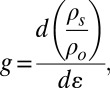 |
where ρo is the resistivity of the film in the relaxed state, ρs is the resistivity under a given strain, and ε is strain. For samples without AgNPs, the gauge factor is <4 for induced tensile strain up to ∼2.4%. On the other hand, gauge factors of ∼24 and 95 are obtained as the AgNP content is increased to 5 and 10 wt %, respectively, for the same tensile strain of ∼2.4%. Notably, the tensile and compressive stress responses are near identical in magnitude, but opposite in sign (Fig. 1C). This trend is expected because compressive and tensile stresses induce smaller and larger gaps between AgNPs, respectively, compared with the relaxed state. This behavior allows the subsequently fabricated e-whisker to detect the direction of bending.
Fig. 1.

CNT-AgNP composite films. (A) Schematic of a CNT–AgNP composite film patterned on a PDMS substrate. (B) Cross-sectional SEM image of a CNT–AgNP composite film on PDMS showing that CNTs are tangled in between AgNPs and polymer binders. (C) Resistivity as a function of strain for CNT–AgNP composites with different AgNP concentrations. (D) Resistance change (ΔR/Ro) as a function of bending cycle (∼2% strain) for 5 and 30 wt % AgNP. Inset shows the current–voltage characteristics before and after 500 cycles.
To examine the mechanical robustness of this composite material system, the resistance of the films after multiple cycles of bending, up to 500 times, was examined for films consisting of 5 and 30 wt % AgNPs (Fig. 1D). In each cycle, the samples were strained by ∼2% and relaxed. This was followed by resistance measurements at the relaxed state. Fig. 1D indicates that the CNT–AgNP composite films exhibit no measurable change of electrical properties up to 500 bending cycles, exhibiting superb mechanical reliability. This is essential for their use in practical whisker devices. It should be noted that for AgNP composite films without nanotubes, the films exhibit poor mechanical robustness with applied strains of ∼0.5% resulting in irreversible degradation of the film conductance caused by cracks and fractures. This highlights the importance of nanotubes in the composite films for providing a conductive matrix with excellent mechanical bendability needed for tolerating large strains.
Next, we focus on the use of CNT–AgNP composite films for e-whisker devices. Fig. 2A illustrates the schematic of an e-whisker device. The device consists of a thin PDMS fiber (width and thickness of ∼250 µm; length of ∼15 mm) with CNT–AgNP lines painted on the top and bottom surfaces and electrically shorted at the tip of the fiber. The resistance of the device is then monitored by applying a voltage between the top and bottom surfaces at the base of the fiber. The AgNP loadings for the painted lines are asymmetric between the top and bottom surfaces. On the top side, 5 wt % AgNP composite is used to serve as the active component for strain detection. On the bottom side, a 30 wt % AgNP composite is used as an interconnect electrode because its resistivity is ∼2 orders of magnitude lower than that of the top electrode (5 wt % AgNP composite), regardless of the strain magnitude. The use of asymmetric top and bottom electrodes is essential in this device configuration as the two electrodes are always under opposite strain (tensile vs. compressive) when the e-whisker is bent. Therefore, a symmetric device does not detect strain (Fig. S2). Because the top electrode is significantly more resistive than the bottom, only the resistance change of this electrode affects the output of the sensor (Fig. 2D). This presents a unique feature of the CNT–AgNP composites that enables a broad tunability in the resistivity with excellent mechanical flexibility.
Fig. 2.

Electronic whiskers. (A) Schematic showing the design of an e-whisker device with 5 and 30 wt % AgNP composite lines patterned on the top and bottom surfaces of a PDMS fiber, respectively. (B) Fabrication process scheme for an e-whisker array. (C) Optical image of a fully fabricated e-whisker array. (D) Circuit diagrams of the e-whiskers for the top and bottom surfaces of the fibers.
The fabrication process of an array of e-whiskers is depicted in Fig. 2B. In brief, a silicon mold was first fabricated by using deep reactive ion etching, consisting of trenches with dimensions of 15 mm long, 250 μm wide, and 250 μm deep. The surface of the Si mold was coated by a fluorinated organosilane monolayer using a molecular vapor deposition system. Elastomeric PDMS precursor was poured into the mold and cured at 70 °C in an oven for ∼2 h. After curing, PDMS is mechanically detached from the mold. Oxygen plasma (30 W, 1 min) was applied on both top and bottom surfaces of PDMS to enhance the subsequent surface adhesion of CNT–AgNP composite inks. The composite mixture is then painted onto the molded PDMS fibers using the pattern shown in Fig. 2A followed by a thermal anneal at 70 °C for 1 h. Fig. 2C shows an optical image of a fully fabricated e-whisker that consists of an array of six fibers.
Next, we examine the sensitivity of the fabricated e-whiskers to airflow. The sensing properties of an individual e-whisker are depicted in Fig. 3. Here, the e-whisker is 15 mm long and is held stationary at one end with the rest of the device being suspended in air. The suspended side of the whisker is displaced up- or downward upon exposure to a directional airflow with controlled direction and velocity (i.e., applied pressure). Fig. 3A shows the normalized resistance change of the device as a function of the exposed airflow speed (bottom axis) and the corresponding applied pressure (top axis) at the tip of the whisker. The conversion of airflow speed to applied pressure is calibrated using a force sensor. The device exhibits a large modulation of the output resistance of ΔR/R0 ∼ 40% for an airflow velocity of v ∼ 3 m/s corresponding to a small applied pressure of P ∼ 5 Pa. The resistance increases when the whisker is bent down (i.e., tensile stress for the top electrode) and decreases when bent upward, which is consistent with the observation in Fig. 1C. The response is near linear for a flow velocity up to ∼3 m/s, which is highly desirable for sensing applications. The sensitivity of the e-whiskers are measured to be  ∼8%/Pa. This pressure sensitivity is ∼10–350× higher than the state-of-the-art capacitive or resistive pressure sensors fabricated using microstructured PDMS (2, 26) and ∼250× higher than silicon-based cantilever sensors (27). The sensitivity to airflow is ∼13.3%/(m/s) up to a 3 m/s flow rate, a range comparable to the one from an average human exhalation. The high sensitivity of our whiskers can be mainly attributed to (i) a strain-sensitive CNT–AgNP composite film with a relatively high gauge factor (∼95), and (ii) the use of a high-aspect-ratio hairlike PDMS substrate with a low spring constant that deforms easily under applied pressure (see Supporting Information and Fig. S3 for details).
Fig. 3.

Electrical characterization of e-whiskers. (A) The ΔR/Ro as a function of compressive and tensile stress induced by gas flow for a representative whisker, where ΔR = R0 − R. The bottom x axis displays the gas-flow velocity used to induce displacement and the top x axis displays the corresponding pressure. (B) Time-resolved resistance change by displacing a whisker upward and downward (∼2 mm displacement) by applied pressure. (C, D) Response time of a whisker when bent downward and relaxed, respectively.
Time-resolved measurements of the e-whiskers were also conducted as 4-Pa pressure was applied upward and downward on the tip of a device in multiple cycles. Fig. 3B shows that the device consistently detects both compressive and tensile stresses (corresponding to upward and downward motions, respectively) with reproducible output signal. Fig. 3 C and D depict that the response time of the sensor is ∼100 ms for both pressure detection and recovery, which is governed by the elastic nature of the PDMS fiber. These results point to a maximum response speed of ∼10 Hz, which is high enough for most sensing applications.
Next we examine the electrical response of an array of individually addressable e-whiskers. Four parallel e-whisker fibers with ∼1.5 mm spacing are fabricated and electrically connected to a readout system consisting of a Wheatstone bridge circuit, a multiplex voltage reader, and a computer for data processing as shown in Fig. 4A. A directional flow of nitrogen gas is then used to simulate a wind flow. Each whisker independently responds with a clear increase or decrease in the output voltage as the gas flow is introduced from the bottom or top, respectively (Fig. 4B). The results clearly depict the consistent and reproducible response of the whiskers and the ability to perform 2D mapping of the gas flow.
Fig. 4.

Parallel array of e-whiskers for real time airflow sensing. (A) Schematic of a readout system used for the measurements. (B) Signal output showing real-time detection of airflow (velocity ∼2 m/s) induced normal to the top or bottom surface of each whisker. Upper show the corresponding pressure profile that is applied on each whisker and Lower displays the corresponding output signal for each whisker. The voltage output is offset for each whisker by 0.5 V in the plot for clarity.
Three-dimensional (3D) mapping of wind flow is also feasible by strategically positioning an array of whiskers on the desired surface. As a proof of concept, seven e-whiskers are mounted on a PDMS hemisphere with a diameter of ∼2.5 cm as shown in Fig. 5A. Each whisker is mounted normal to the surface of the PDMS hemisphere and distributed with equal spacing. Silver interconnect lines are painted on the surface of the PDMS for reading out signals from individual pixels (i.e., whiskers) by an external electronic board. A nitrogen gas line set ∼4 cm away from the PDMS substrate with a directional flow velocity of ∼5 m/s is used to simulate wind. The direction of the gas line is manipulated to control the wind direction. Fig. 5C shows the real-time voltage output signal from the e-whiskers as the “wind” flows toward the front side of the PDMS hemisphere, facing whiskers 5–7 (as marked in Fig. 5 A and B). Whiskers 5–7 clearly exhibit the highest voltage drops corresponding to the largest displacements because they are in the direct path of the gas flow. In contrast, whiskers 2–4 show smaller voltage drops because they are in indirect path of the flow. Finally, whisker 1, which is fully shadowed from the gas flow, exhibits nearly no response. The whiskers exhibit high sensitivity and small fluctuations in the gas flow over the structure are clearly mapped by the output voltage signal. A 3D airflow map at a fixed time is obtained and plotted as Fig. 5D by converting the output voltage drop (i.e., resistance change) of each whisker to gas velocity according to Fig. 3A. The results demonstrate the ability to map airflow in real time with high sensitivity, and provide just one example system which these e-whiskers could be used for monitoring the environment.
Fig. 5.

An array of seven vertically placed e-whiskers for 3D mapping of wind. (A, B) Optical images of the experimental sample. There are seven whiskers placed normal to the surface of a PDMS hemisphere with near equal spacing. Wind is simulated by a N2 gas line (from a 1/4” tubing set to 5 psi and placed ∼4 cm away from the PDMS substrate). (C) Output voltage signals through the readout system for the e-whisker array. Each output signal (1–7) corresponds to the e-whisker number in the optical images of A and B. (D) Three-dimensional resistance change mapping corresponding to the measurement at 3.6 s in C.
In summary, we have developed highly sensitive electronic whiskers by painting CNT–AgNP composite films onto hairlike PDMS fibers. The devices exhibit large resistance modulation upon pressure-induced bending with a sensitivity of ∼8%/Pa, which is the highest for all reported tactile sensors. E-whisker arrays with different configurations were designed and successfully demonstrated for 2D and 3D mapping of wind flow. The work here represents a type of highly responsive tactile sensor networks for real-time monitoring of environmental effects. The ease of fabrication, light weight, and excellent performance of the e-whiskers may enable a wide range of applications for advanced robotics, human–machine user interfaces, and biological applications.
Supplementary Material
Acknowledgments
This work was funded by Defense Advanced Research Projects Agency, Defense Sciences Office Maximum Mobility and Manipulation.
Footnotes
The authors declare no conflict of interest.
This article is a PNAS Direct Submission.
This article contains supporting information online at www.pnas.org/lookup/suppl/doi:10.1073/pnas.1317920111/-/DCSupplemental.
References
- 1.Kim DH, et al. Epidermal electronics. Science. 2011;333(6044):838–843. doi: 10.1126/science.1206157. [DOI] [PubMed] [Google Scholar]
- 2.Schwartz G, et al. Flexible polymer transistors with high pressure sensitivity for application in electronic skin and health monitoring. Nat Commun. 2013;4:1859. doi: 10.1038/ncomms2832. [DOI] [PubMed] [Google Scholar]
- 3.Someya T, et al. Conformable, flexible, large-area networks of pressure and thermal sensors with organic transistor active matrixes. Proc Natl Acad Sci USA. 2005;102(35):12321–12325. doi: 10.1073/pnas.0502392102. [DOI] [PMC free article] [PubMed] [Google Scholar]
- 4.Takei K, et al. Nanowire active-matrix circuitry for low-voltage macroscale artificial skin. Nat Mater. 2010;9(10):821–826. doi: 10.1038/nmat2835. [DOI] [PubMed] [Google Scholar]
- 5.Song YM, et al. Digital cameras with designs inspired by the arthropod eye. Nature. 2013;497(7447):95–99. doi: 10.1038/nature12083. [DOI] [PubMed] [Google Scholar]
- 6.Brecht M, Preilowski B, Merzenich MM. Functional architecture of the mystacial vibrissae. Behav Brain Res. 1997;84(1-2):81–97. doi: 10.1016/s0166-4328(97)83328-1. [DOI] [PubMed] [Google Scholar]
- 7.Grant RA, Mitchinson B, Fox CW, Prescott TJ. Active touch sensing in the rat: anticipatory and regulatory control of whisker movements during surface exploration. J Neurophysiol. 2009;101(2):862–874. doi: 10.1152/jn.90783.2008. [DOI] [PMC free article] [PubMed] [Google Scholar]
- 8.Kaneko M, Tsuji T. A whisker tracing sensor with 5 µm sensitivity. Proc IEEE Int Conf Robot Syst. 2000;4:3907–3912. [Google Scholar]
- 9.Kim D, Moller R. Biomimetic whiskers for shape recognition. Robot Auton Syst. 2007;55(3):229–243. [Google Scholar]
- 10.Lungarella M, Hafner VV, Pfeifer R, Yokoi H. An artificial whisker sensor for robotics. Proc IEEE Int Conf Robot Syst. 2002;3:2931–2936. [Google Scholar]
- 11.Solomon JH, Hartmann MJZ. Artificial whiskers suitable for array implementation: Accounting for lateral slip and surface friction. IEEE Trans Robot. 2008;24(5):1157–1167. [Google Scholar]
- 12.Stocking JB, et al. Proc Ninth IEEE Sensors Conf. Kona, HI: IEEE; 2010. A capacitance-based whisker-like artificial sensor for fluid motion sensing; pp. 2224–2229. [Google Scholar]
- 13.Chun KY, et al. Highly conductive, printable and stretchable composite films of carbon nanotubes and silver. Nat Nanotechnol. 2010;5(12):853–857. doi: 10.1038/nnano.2010.232. [DOI] [PubMed] [Google Scholar]
- 14.Lipomi DJ, et al. Skin-like pressure and strain sensors based on transparent elastic films of carbon nanotubes. Nat Nanotechnol. 2011;6(12):788–792. doi: 10.1038/nnano.2011.184. [DOI] [PubMed] [Google Scholar]
- 15.Yamada T, et al. A stretchable carbon nanotube strain sensor for human-motion detection. Nat Nanotechnol. 2011;6(5):296–301. doi: 10.1038/nnano.2011.36. [DOI] [PubMed] [Google Scholar]
- 16.Yu ZB, Niu XF, Liu ZT, Pei QB. Intrinsically stretchable polymer light-emitting devices using carbon nanotube-polymer composite electrodes. Adv Mater. 2011;23(34):3989–3994. doi: 10.1002/adma.201101986. [DOI] [PubMed] [Google Scholar]
- 17.Pang C, et al. A flexible and highly sensitive strain-gauge sensor using reversible interlocking of nanofibres. Nat Mater. 2012;11(9):795–801. doi: 10.1038/nmat3380. [DOI] [PubMed] [Google Scholar]
- 18.Xiao X, et al. High-strain sensors based on ZnO nanowire/polystyrene hybridized flexible films. Adv Mater. 2011;23(45):5440–5444. doi: 10.1002/adma.201103406. [DOI] [PubMed] [Google Scholar]
- 19.Yu ZB, et al. Highly flexible silver nanowire electrodes for shape-memory polymer light-emitting diodes. Adv Mater. 2011;23(5):664–668. doi: 10.1002/adma.201003398. [DOI] [PubMed] [Google Scholar]
- 20.Li X, et al. Stretchable and highly sensitive graphene-on-polymer strain sensors. Sci Rep. 2012;2:870. doi: 10.1038/srep00870. [DOI] [PMC free article] [PubMed] [Google Scholar]
- 21.Farcau C, et al. High-sensitivity strain gauge based on a single wire of gold nanoparticles fabricated by stop-and-go convective self-assembly. ACS Nano. 2011;5(9):7137–7143. doi: 10.1021/nn201833y. [DOI] [PubMed] [Google Scholar]
- 22.Herrmann J, et al. Nanoparticle films as sensitive strain gauges. Appl Phys Lett. 2007;91(18):183105. [Google Scholar]
- 23.Arthur D, et al. Carbon nanomaterial commercialization: Lessons for graphene from carbon nanotubes. MRS Bull. 2012;37(12):1297–1306. [Google Scholar]
- 24.Sekitani T, et al. A rubberlike stretchable active matrix using elastic conductors. Science. 2008;321(5895):1468–1472. doi: 10.1126/science.1160309. [DOI] [PubMed] [Google Scholar]
- 25.Kim Y, et al. Stretchable nanoparticle conductors with self-organized conductive pathways. Nature. 2013;500(7460):59–63. doi: 10.1038/nature12401. [DOI] [PubMed] [Google Scholar]
- 26.Liu XC, et al. A highly sensitive pressure sensor using a Au-patterned polydimethylsiloxane membrane for biosensing applications. J Micromech Microeng. 2013;23(2):025022. [Google Scholar]
- 27.Takahashi H, Dung NM, Matsumoto K, Shimoyama I. Differential pressure sensor using a piezoresistive cantilever. J Micromech Microeng. 2012;22(5):055015. [Google Scholar]
Associated Data
This section collects any data citations, data availability statements, or supplementary materials included in this article.