Abstract
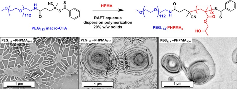
A poly(ethylene glycol) (PEG) macromolecular chain transfer agent (macro-CTA) is prepared in high yield (>95%) with 97% dithiobenzoate chain-end functionality in a three-step synthesis starting from a monohydroxy PEG113 precursor. This PEG113-dithiobenzoate is then used for the reversible addition–fragmentation chain transfer (RAFT) aqueous dispersion polymerization of 2-hydroxypropyl methacrylate (HPMA). Polymerizations conducted under optimized conditions at 50 °C led to high conversions as judged by 1H NMR spectroscopy and relatively low diblock copolymer polydispersities (Mw/Mn < 1.25) as judged by GPC. The latter technique also indicated good blocking efficiencies, since there was minimal PEG113 macro-CTA contamination. Systematic variation of the mean degree of polymerization of the core-forming PHPMA block allowed PEG113-PHPMAx diblock copolymer spheres, worms, or vesicles to be prepared at up to 17.5% w/w solids, as judged by dynamic light scattering and transmission electron microscopy studies. Small-angle X-ray scattering (SAXS) analysis revealed that more exotic oligolamellar vesicles were observed at 20% w/w solids when targeting highly asymmetric diblock compositions. Detailed analysis of SAXS curves indicated that the mean number of membranes per oligolamellar vesicle is approximately three. A PEG113-PHPMAx phase diagram was constructed to enable the reproducible targeting of pure phases, as opposed to mixed morphologies (e.g., spheres plus worms or worms plus vesicles). This new RAFT PISA formulation is expected to be important for the rational and efficient synthesis of a wide range of biocompatible, thermo-responsive PEGylated diblock copolymer nano-objects for various biomedical applications.
Introduction
It is well-known that conjugation of a hydrophilic poly(ethylene glycol) (PEG; also known as poly(ethylene oxide) or PEO) chain to a biologically relevant molecule typically enhances its water solubility and hydrolytic stability.1,2 In the case of proteins, this so-called ‘PEGylation’ approach can also significantly reduce immunogenicity.1−4 Moreover, PEGylation can also extend in vivo circulation lifetimes for important biomolecules such as insulin, allowing a lower dose frequency and hence greater patient compliance.5,6 These attractive properties have led to the recent development of a number of FDA-approved PEGylated therapeutic entities.1,5 Various PEGylation strategies have been developed, such as the site-specific attachment of PEG chains to proteins via disulfide linkages6−8 or direct polymerization of oligo(ethylene glycol) methacrylate from specific surface sites on proteins.3
There are many examples of PEG-based amphiphilic diblock copolymers for drug delivery applications, where the hydrophobic core-forming block may comprise poly(l-lysine) (PLL), poly(lactic acid) (PLA), or poly(ε-caprolactone) (PCL).9−15 PCL and PLA both undergo slow hydrolytic degradation,9,10 while disulfide bonds can be introduced to produce block copolymer nano-objects that only degrade under reductive conditions, such as those found within the cell cytoplasm.16 Pluronics (sometimes called Poloxamers) are commercially available ABA triblock copolymers comprising two outer PEG ‘A’ blocks and a central poly(propylene glycol) ‘B’ block. These copolymers exhibit thermo-responsive behavior and undergo spontaneous self-assembly in aqueous solution to form various nanostructures depending on the copolymer concentration, temperature, salt concentration, and relative block lengths.17−21 Various types of micellar gels can be obtained with tunable rheological properties.17 Moreover, it has been shown that these copolymers usually exhibit low cytotoxicities and can also bind to cell membranes.18,22
It is well-known that amphiphilic block copolymers can self-assemble in a suitable selective solvent to produce cylindrical/worm-like micelles, toroids, tubes, or vesicles, in addition to the more common spherical micelles.11,23−27 This behavior is broadly analogous to that of small molecule surfactants, where the precise nanostructure is dictated by the packing parameter, P.24,25,28,29 The value of P depends on the relative volume fractions of the hydrophilic and hydrophobic blocks and the interfacial energy associated with the diblock junction. In contrast to small molecule amphiphiles, the rate of exchange of unimers between colloidal aggregates and individual diblock copolymer chains can be negligible, leading to a range of kinetically frozen structures.30 Since the pioneering work by Discher and co-workers, anisotropic (or worm-like) block copolymer nano-objects have attracted considerable interest due to their qualitatively different circulation times and cell entry behavior compared to isotropic nanoparticles.11,12
Traditionally, diblock copolymers have been synthesized using controlled/living polymerization techniques in a good solvent for both blocks. After purification, the desired self-assembly is usually achieved by postpolymerization processing, which is typically conducted in highly dilute solution (<1%).31 Recent synthetic advances in polymerization-induced self-assembly (PISA) now allow spherical micelles, worm-like micelles or vesicles composed of well-defined AB diblock (or ABC triblock) copolymers to be prepared directly in concentrated aqueous solution via either RAFT dispersion or emulsion polymerization.32−42 In particular, we have reported robust formulations comprising thermo-responsive PHPMA chains as the hydrophobic core-forming block and either poly(2-methacryloyloxy)ethyl phosphorylcholine (PMPC)36 or poly(glycerol monomethacrylate) (PGMA)33,35,41,42 as the hydrophilic stabilizer block. In each case detailed phase diagrams were constructed for a fixed degree of polymerization of the stabilizer block, using the degree of polymerization of the core-forming block and the diblock copolymer concentration as variables. This approach enables the desired nano-object morphology to be targeted consistently.34,36 Moreover, if a relatively short stabilizer block is utilized, a morphological evolution from spheres to worms to vesicles can be observed during such PISA syntheses, which is driven by the reduction in molecular curvature as the core-forming PHPMA block grows.33
It should be emphasized that, unlike traditional equilibrium phase diagrams, these phase diagrams contain kinetically trapped morphologies as well as thermodynamically stable morphologies. The former are frustrated spheres prepared at relatively low copolymer concentrations, whereas the latter are obtained at high copolymer concentrations. It has been suggested to us that ‘state diagrams’ may be a more appropriate term. However, strictly speaking, state diagrams only refer to solids, liquids, and gases, rather than the various copolymer morphologies that are of interest here. Thus in the present work we continue to use the phrase ‘phase diagram’ with the above caveat.
As far as we are aware, almost all previous PISA formulations have used macromolecular chain transfer agents (macro-CTAs) derived from various vinyl monomers.34,36,37,39,43−45 Moreover, the very few reports of the use of PEG macro-CTAs in heterogeneous media have often achieved only relatively low RAFT end-group functionality (∼85–90%), which inevitably reduces the blocking efficiency.47−50 Herein, a commercially available near-monodisperse monohydroxy-terminated PEG precursor is efficiently converted into a well-defined PEG-dithiobenzoate macro-CTA via a high-yielding multistep synthesis involving a monoaminated PEG113 intermediate (see Schemes 1 and S1). This macro-CTA is subsequently utilized to synthesize a wide range of well-defined diblock copolymer nano-objects via the RAFT aqueous dispersion polymerization of HPMA.
Scheme 1. Synthesis of (a) a Well-Defined PEG-Based Macro-CTA Suitable for RAFT Polymerizations and (b) Various PEG113-PHPMAx Diblock Copolymer Nano-Objects Produced via RAFT Aqueous Dispersion Polymerization of HPMA Using the Principle of Polymerization-Induced Self-Assembly (PISA).
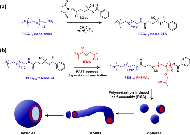
One advantage of such a PEG-based macro-CTA is that the same mean degree of polymerization (in this case 113 ethylene glycol units) can be consistently obtained. This is not necessarily the case for the various (meth)acrylic RAFT macro-CTAs that have been reported by both ourselves and others.33−46,51 Indeed, it is relatively difficult to prepare the latter macro-CTAs with a specific desired mean degree of polymerization since such syntheses are usually terminated at intermediate conversions to ensure high chain-end fidelity. It is perhaps also worth emphasizing that the RAFT dithiobenzoate end-group is attached to the PEG chain via an amide bond, which is rather more resistant to hydrolytic degradation under physiological conditions than the ester bond linkage that is more typically reported in the literature.52
The RAFT aqueous dispersion polymerization of HPMA using this PEG113 macro-CTA has been optimized with respect to the solution temperature and the total solids concentration so as to achieve high conversions, low polydispersities, and good blocking efficiencies for the resulting diblock copolymer nano-objects. This enabled construction of a detailed phase diagram that allows the reproducible targeting of pure copolymer morphologies. In addition to the expected spheres, worms and vesicles, oligolamellar vesicles are obtained for the first time using PISA, and this phase is characterized together with a complete chain of self-assembled structural morphologies using transmission electron microscopy (TEM) and small-angle X-ray scattering (SAXS).
Results and Discussion
First, a mono-aminated PEG intermediate was prepared in 83% yield via a two-step synthesis starting from the monohydroxy-capped PEG precursor according to a previously reported literature protocol.53 The mean degree of amination was determined to be 98% using 1H NMR spectroscopy (Figure S1a). Then the N-hydroxysuccinimide activated ester of 4-cyano-4-(phenylcarbonothioylthio) pentanoic acid (CPADB) was conjugated to the terminal primary amine group on the PEG113 chain. It is well-documented that direct carbodiimide coupling only produces PEG macro-CTAs with relatively low blocking efficiencies.54 However, previous studies suggested that activating the carboxylic acid provides a highly efficient means of conjugating (macro)molecules to primary amine-functional PEG.55 Thus the succinimide-modified cyanopentanoate dithiobenzoate (SCPDB) CTA was reacted with the PEG113-NH2 precursor to yield the PEG113-DB macro-CTA. After purification, the extent of end-group modification was determined by 1H NMR spectroscopy (see Figure S2). Three distinct proton signals attributed to the RAFT end-group were visible: (i) the aromatic signals at δ 7.3–7.8 ppm (see peaks i and j in Figure S1b); (ii) the four methylene protons at δ 2.3–2.7 ppm (see peaks f and g) assigned to the pentanoic acid end-group; (iii) the three methyl protons adjacent to the nitrile group at δ 1.8 ppm (see peak h). Comparison of the integrated intensities of each of these three signals to that of the ethylene glycol protons in the PEG chain at δ 3.0–4.0 ppm indicated a mean degree of dithiobenzoate functionalization of 93 ± 9%. We also used visible absorption spectroscopy as a complementary method for determining the degree of end-group functionalization. A calibration plot was prepared from a series of methanolic solutions of CPADB; this small molecule closely resembles the RAFT end-group that is conjugated to the PEG chain, which is a prerequisite for reliable end-group analysis using this technique.56 The visible absorption spectrum recorded for PEG113-DB (see Figure S3a) is almost identical to that of the CPADB spectrum, with a peak maximum at ∼516 nm being observed in both cases. From the CPADB calibration plot (see Figure S3b), a molar extinction coefficient of 104 800 ± 640 L mol–1 cm–1 was calculated. Assuming an identical molar extinction coefficient for the terminal dithiobenzoate groups on the PEG113-DB chains, the mean degree of functionalization for this RAFT macro-CTA was calculated to be 97 ± 2%. Given that visible absorption spectroscopy is more sensitive than 1H NMR spectroscopy, this value was considered to be more accurate than that indicated by 1H NMR analysis. It should be noted that the 3–7% nonfunctionalized PEG impurity indicated by end-group analysis may result from a small amount of PEG226 secondary amine during the reaction with ammonia. This is consistent with the GPC chromatogram for the PEG113 macro-CTA shown in Figure 1, which contains a minor high molecular weight component at 15.4 min.
Figure 1.
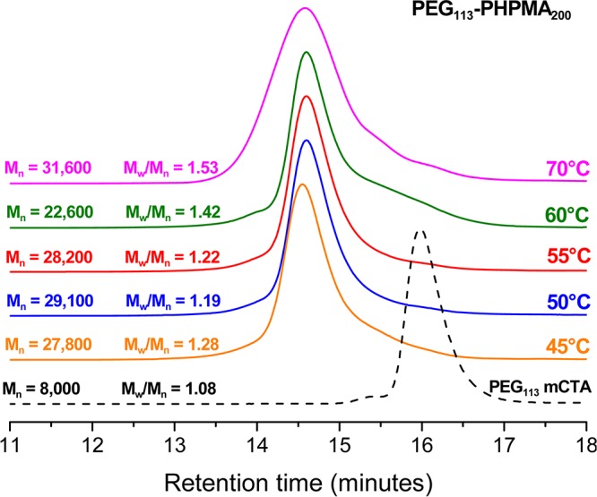
Gel permeation chromatograms obtained for PEG113-PHPMA200 diblock copolymer syntheses conducted at various temperatures using RAFT aqueous dispersion polymerization at 10% w/w solids at a [PEG113-DB]/[initiator] molar ratio of 3.0. Suitable free radical initiators were selected for a given reaction temperature: ACVA was used at 70 °C, AIBA was employed at 55 and 60 °C, and AIPD was utilized at 50 and 45 °C (see main text for details).
RAFT Aqueous Dispersion Polymerization of HPMA
To assess the efficiency of this new PEG113-DB RAFT agent, the RAFT aqueous dispersion polymerization of HPMA was conducted at 10% w/w solids, targeting a mean degree of polymerization (DP) of 200 for the core-forming PHPMA block. Initially, such syntheses were performed at 70 °C, as previously reported by Armes and co-workers for methacrylic-based macro-CTAs.33 However, although 1H NMR studies indicated that very high HPMA conversions were achieved (data not shown), some macroscopic precipitation was also observed. This is presumably due to the reduced aqueous solubility of the PEG chains at this reaction temperature.57 Moreover, THF GPC studies of the copolymer product indicated a relatively high polydispersity (Mw/Mn = 1.53) and a prominent low molecular weight shoulder, indicating a relatively poor blocking efficiency (see Figure 1). In the light of these observations, a further series of PEG113-PHPMA200 syntheses were conducted over various reaction temperatures ranging between 45 and 60 °C. An appropriate radical initiator was selected in order to maintain a sufficient radical flux at each temperature. Thus 2,2′-azobis(2-methylpropionamide) dihydrochloride (AIBA) was used for copolymer syntheses performed at 55 or 60 °C, whereas 2,2′-azobis[2-(2-imidazolin-2-yl)propane dihydrochloride (AIPD) was employed for syntheses conducted at 45 or 50 °C. In all cases, more than 99% HPMA conversion was achieved.
THF GPC studies indicated that the 50 °C synthesis produced the most well-defined PEG113-PHPMA200 diblock copolymer, as judged by its relatively low polydispersity and minimal homopolymer contamination. The latter observation confirms the high mean degree of functionalization of the PEG113-DB macro-CTA chains indicated by the visible absorption spectroscopy studies. Thus this optimized RAFT aqueous dispersion polymerization formulation (50 °C; AIPD initiator; [PEG113-DB]/[AIPD] = 3.0) was selected for all subsequent diblock copolymer syntheses described in this study. A kinetic plot for the polymerization of HPMA (Figure 2, target DP = 300) at 50 °C using the PEG113 macro-CTA was obtained by periodic sampling of the reaction solution. The semilogarithmic plot in Figure 2 clearly shows three distinct regimes. There is an initial induction period of ∼50 min, which is commonly observed for RAFT polymerizations.58−61 The second regime, which occurs between 60 and 120 min, corresponds to the onset of polymerization and the formation of molecularly dissolved diblock copolymer chains.33 In the third regime, there is a dramatic increase in the rate of polymerization, which corresponds to the onset of micellar nucleation. At this point, unreacted HPMA monomer enters the micelle cores to solvate the hydrophobic PHPMA chains, which produces a high local monomer concentration and hence the observed rate enhancement.33 Interpolation of the green and blue lines indicates that micellar nucleation occurs at around 110 min, which corresponds to 45% HPMA conversion for this particular formulation. This intermediate conversion corresponds to a mean degree of polymerization of 135 for the core-forming PHPMA block, which is somewhat higher than the critical DP of ∼92 previously reported by Blanazs et al. for a PGMA47 macro-CTA utilized to polymerize HPMA (target DP = 200) at 70 °C.33 Presumably, the growing PHPMA chains are more effectively solubilized by the relatively long hydrophilic PEG113 macro-CTA in the aqueous reaction solution. However, other parameters cannot be ignored. For example, the lower polymerization temperature of 50 °C used in the present work is known to affect the water solubility of the HPMA monomer.63 GPC analysis (see inset in Figure 2) confirms that the evolution of Mn with HPMA monomer conversion is linear, and the polydispersity of the final diblock copolymer is relatively low (Mw/Mn = 1.22). These characteristics are typical for a pseudo-living radical polymerization and indicate that good control is maintained under dispersion polymerization conditions, despite the relatively low CTA/initiator molar ratio used in these RAFT syntheses.58−61 It is also noteworthy that the non-zero y-intercept is simply due to the PEG113 macro-CTA, which has an apparent Mn of around 8000 (vs poly(methyl methacrylate) calibration standards) when analyzed using THF GPC. The effect of increasing the target DP of the core-forming PHPMA block from 100 to 400 was systematically investigated by preparing a series of PEG113-PHPMAx copolymers at a fixed concentration of 10% w/w solids. In each case more than 99% HPMA conversion was attained, as judged by the eventual disappearance of the vinyl signals at δ 6.2–6.6 in the 1H NMR spectra (Figure S1c). For target DPs of 100–220, GPC studies indicated that RAFT control was maintained, with a systematic increase in Mn and relatively low polydispersities (Mw/Mn = 1.16–1.19) being observed (Figure 3). However, a significant increase in polydispersity was observed when targeting DPs of 300 or 400 (Mw/Mn = 1.39 and 1.78, respectively). This problem is well-documented33,36,63 and is actually due to the presence of a small amount (<0.3 mol %) of dimethacrylate in the HPMA monomer, rather than loss of RAFT control. This impurity inevitably leads to light branching as longer PHPMA chains are targeted.64−66
Figure 2.
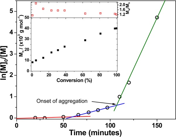
Kinetics of polymerization of HPMA via RAFT aqueous dispersion polymerization at 50 °C and 10% w/w solids. A PEG113-PHPMA300 diblock copolymer was targeted using a [PEG113-DB]/[AIPD] molar ratio of 3.0. The semilogarithmic plot shows three regimes: an initial induction period up to 50 min, a slow rate of solution polymerization between 50 and 60 and 120 min, and a relatively fast rate of polymerization after 120 min. The latter time corresponds to the onset of micellar nucleation, which occurs at an HPMA conversion of around 45%. The inset shows the GPC curves obtained for a subset of these kinetic data, indicating a linear evolution of Mn and a gradual reduction in copolymer polydispersity with monomer conversion.
Figure 3.
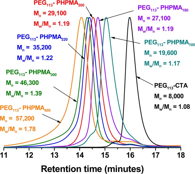
Gel permeation chromatograms (THF eluent, refractive index detector) obtained for a series of PEG113-PHPMAx diblock copolymers synthesized at 50 °C and 10% w/w solids, where x is systematically varied from 100 to 400. Calibration was achieved using a series of near-monodisperse poly(methyl methacrylate) standards.
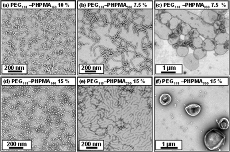
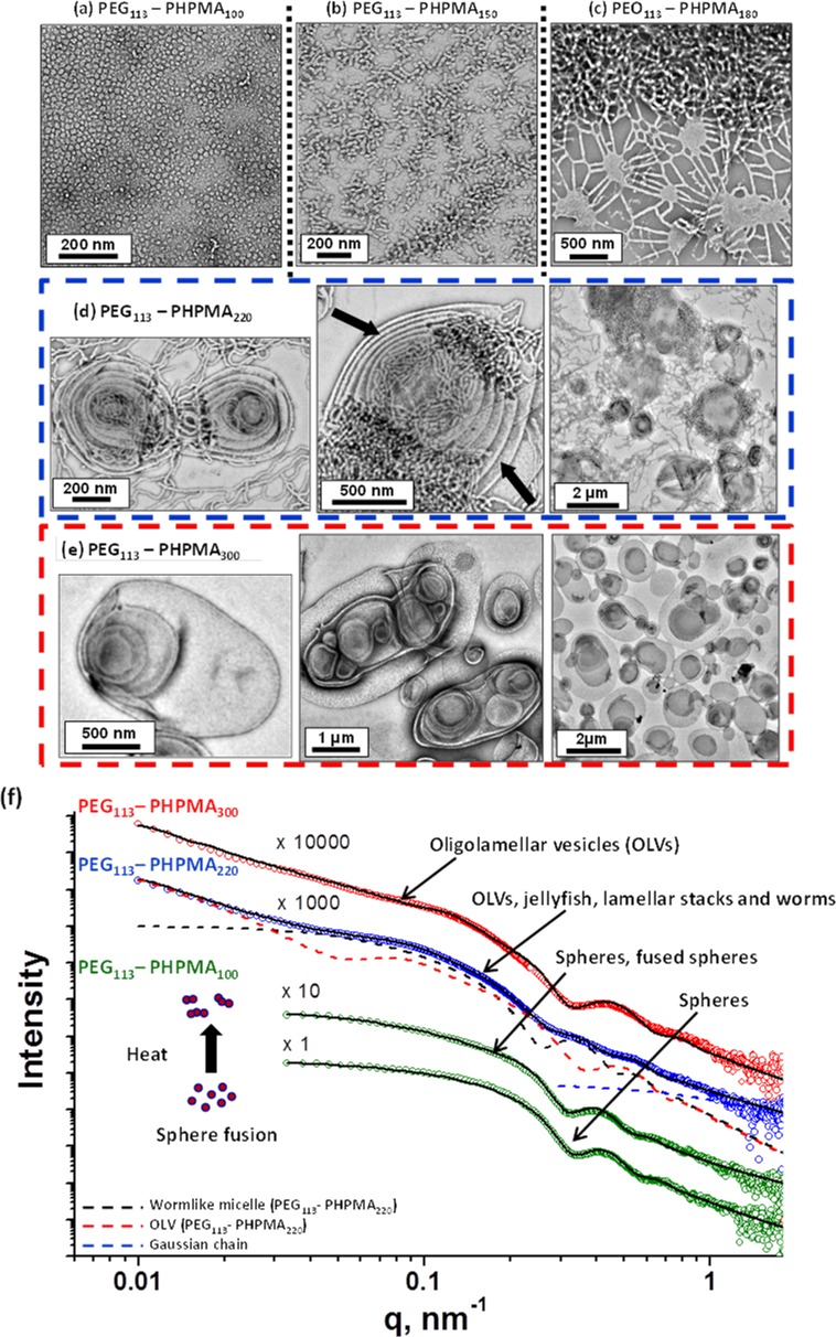
Visual inspection of the final aqueous dispersions indicated progressively greater turbidity as the DP of the PHPMA core-forming block was increased, suggesting systematic variation in the size and/or morphology of the colloidal PEG113-PHPMAx nano-objects prepared under these conditions. This was confirmed by DLS and TEM studies (see Table S1). A monomodal distribution with an intensity-average diameter of 26 nm (polydispersity, PDI = 0.06) was recorded for PEG113-PHPMA100, which suggested the formation of near-monodisperse spherical micelles. For PEG113-PHPMA180, there was an increase in both the mean diameter and polydispersity (38 nm, PDI = 0.29), suggesting a possible change in copolymer morphology due to the greater volume fraction of the hydrophobic block. This was confirmed by TEM studies, which revealed a mixture of spheres and short worms. TEM images obtained for PHPMA DPs of 200–220 indicated a pure worm phase. These dispersions formed soft, reasonably transparent gels, presumably because multiple interworm contacts lead to a percolation network.42,67 In contrast, PEG113-PHPMA250 formed a mixed phase consisting of worms, vesicles, and some ‘jellyfish’ structures, which have previously been observed as important intermediates for the worm-to-vesicle transition.33 A pure vesicle phase was obtained when the target DP of the PHPMA block exceeded 250, with DLS intensity-average diameters of either 359 nm (PDI = 0.05) or 377 nm (PDI = 0.07) being observed for DPs of 300 or 400, respectively. To further investigate the RAFT aqueous dispersion polymerization of HPMA at 50 °C, a detailed phase diagram was established by utilizing the same systematic approach adopted for related PISA formulations.34,36,43,44 This phase diagram is shown in Figure 4, with some representative TEM images for the various pure phases being depicted in Figure 5. For concentrations up to 17.5% w/w, the phase diagram resembles those previously reported for PHPMA-based PISA formulations. At the lowest concentration investigated (5.0% w/w), only mixed phases were observed. Presumably, this simply reflects the reduced probability of inter-sphere fusion under these conditions, which is considered to be the first step in the generation of higher order morphologies.33 TEM studies on PEG113-PHPMAx nano-objects prepared at between 7.5 and 17.5% w/w confirm the presence of pure sphere, worm, and vesicle phases. Pure spheres are typically observed at PHPMA DPs of 150 or less. Pure worm phases are observed at DPs between 180 and 220, but this upper limit is reduced to 200 at higher copolymer concentrations (15% w/w). The relatively narrow worm phase window is almost encompassed by two mixed phases: spheres plus worms and worms plus vesicles. Conventional unilamellar (i.e., single-walled) vesicles are generally observed above DP 250. In addition to these various structures, some ‘jellyfish’ are observed; this is a known intermediate in the morphological transformation of worms into vesicles33 (see Figure 6). THF GPC studies conducted on these copolymers indicate diblock copolymer chains of relatively low polydispersity for PHPMA DPs below 300 (see Table S1). When syntheses were conducted at 20% w/w solids, GPC polydispersities ranged from 1.32 to 1.84 for target DPs of 100 to 250, which are generally somewhat higher than those observed for the same copolymer compositions prepared at 10% w/w (Mw/Mn = 1.17–1.32). Moreover, Mw/Mn values of 3.8 and 18.7 were obtained when targeting PHPMA DPs of 300 and 400, respectively. These polydispersities are much higher than those observed for the equivalent diblock copolymers prepared at lower concentrations (e.g., Mw/Mn = 1.32 and 1.86 respectively at 15% w/w) and cannot be solely attributed to the dimethacrylate impurities in HPMA monomer. This was confirmed by conducting a PEG113-PHPMA300 synthesis at 20% w/w using purified HPMA monomer (column chromatography reduces the level of dimethacrylate impurity substantially33), since the copolymer polydispersity could only be reduced to 1.49 (Figure S5). This suggests some loss of RAFT control under these conditions. In principle, the relatively high viscosity of the reaction mixture may retard diffusion of the macro-CTA, but further studies are clearly warranted. For the 20% w/w copolymer syntheses, PHPMA DPs of 100 and 150 produced spheres and a mixed phase of spheres and short worms (see Figures 7a, 7b), respectively. However, a remarkable range of diblock copolymer nano-objects was observed when targeting higher PHPMA DPs. For example, a mixed phase containing flat lamellar disks interlinked by long worms was observed for the PEG113-PHPMA180 dispersion (Figure 7c). Similar morphologies have been previously reported by Jain and Bates for postpolymerization processed amphiphilic PEG-based diblock copolymers.68 For a PHPMA DP of 220, a viscous gel was formed that contained a wide range of exotic structures (see Figure 7d). As well as worms and some vesicles, many ill-defined lamellae and jellyfish were also observed. The presence of these exotic nanostructures suggests that the preferred molecular curvature of the copolymer chains is intermediate between that for cylindrical and that for flat lamellar sheets. Presumably, this parameter approaches a relatively narrow range whereby the energy penalty required to form the edges of large lamellar sheets is less than the energy required for these sheet to wrap up to form vesicles.69,70 TEM studies indicate that further increasing the PHPMA DP up to 250–300 (Figure 7e) yields mostly large ‘vesicles within vesicles’ (a.k.a., oligolamellar vesicles, OLVs) and some nanotubes. These aqueous dispersions also formed opaque gels, which is most likely due to close packing of the lamellae and/or vesicles.
Figure 4.
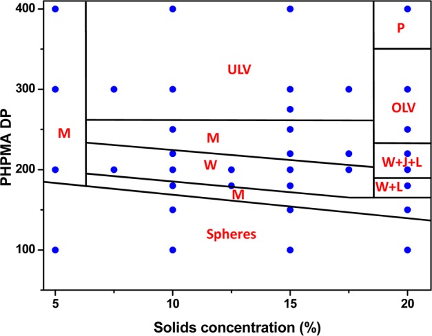
Phase diagram elucidated for the RAFT aqueous dispersion polymerization of HPMA at 50 °C using a PEG113-DB macro-CTA based on combined TEM and DLS studies. Phase regions consist of spheres (S), worms (W), unilamellar vesicles (ULV), oligolamellar vesicles (OLV), ill-defined lamellae (L), jellyfish (J), mixed phases (M), and a precipitate phase (P).
Figure 5.
Representative TEM images obtained for PEG113-PHPMAx diblock copolymers (where x = 150, 200, or 400): (a) spheres prepared at 10% w/w; (b) worms prepared at 7.5% w/w; (c) vesicles prepared at 7.5% w/w; (d) spheres prepared at 15% w/w; (e) worms prepared at 15% w/w; and (f) vesicles prepared at 15% w/w.
Figure 6.
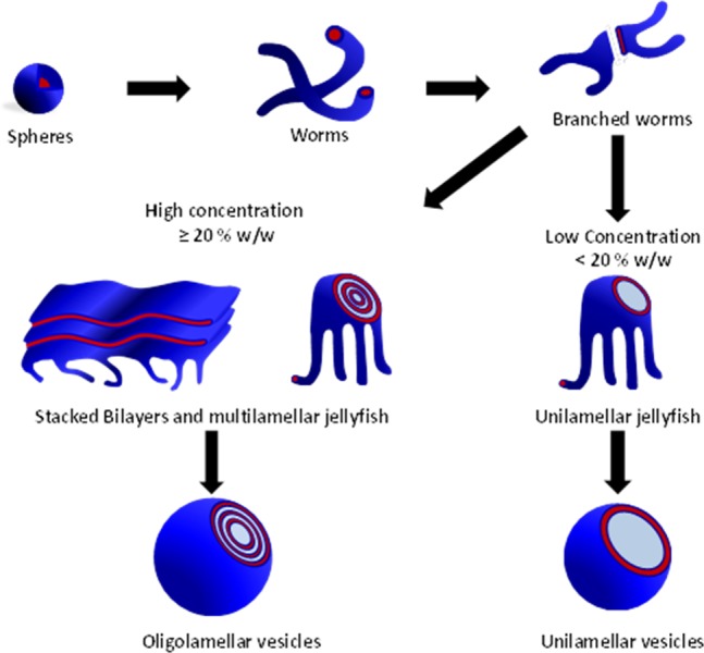
Schematic formation of the oligolamellar vesicles obtained from PISA syntheses of PEG113-PHPMAx conducted at 20% w/w solids and the unilamellar vesicles formed when the PISA syntheses are conducted at lower copolymer concentrations.
Figure 7.
Representative TEM images obtained for the various PEG113-PHPMAx diblock copolymer nano-objects produced using a PISA formulation for the RAFT dispersion polymerization of HPMA at 20% w/w solids. (a) PEG113-PHPMA100; (b) PEG113-PHPMA150; (c) PEG113-PHPMA180; (d) PEG113-PHPMA220 jellyfish and stacked lamellae (black arrows); (e) PEG113-PHPMA300 oligolamellar vesicles. (f) SAXS patterns (symbols) and data fits (solid lines) obtained for the respective dilute (1.0% w/w) copolymer dispersions. Fitting curves for three populations used for the PEG113-PHPMA220 SAXS data (blue circles) analysis are also shown: worms (black dashed line), oligolamellar structures (red dashed line), and Gaussian chain (blue dashed line) The upper green circles SAXS pattern shows the thermally-induced fusion of a 1.0% w/w dispersion of PEG113-PHPMA100 spheres to form short worms after being exposed to the synchrotron X-ray beam for 1 s.
SAXS Analysis
Scattering techniques, in particular SAXS, is an ideal in situ integral method for assessing the morphologies of diblock copolymer nanoparticles. Since the TEM images of the dispersions synthesized at 20% w/w reveal morphologies that have not previously been observed in such PISA syntheses (see Figures 4 and 7a–e), statistically robust SAXS measurements were conducted to exclude possible artifacts resulting from the TEM sample preparation. Unlike TEM, SAXS is conducted on aqueous dispersions and is averaged over many millions of nanoparticles. Since a wide range of diblock copolymer morphologies (spheres, worms, stacked lamellae, and both unilamellar and oligolamellar vesicles) were observed for the dispersions synthesized at 20% w/w (Figure 4), various structural models had to be used to analyze the SAXS data. Both form and structure factors for these models are discussed below. SAXS scattering patterns (see Figure 7f) were consistent with the corresponding TEM images (see Figure 7a–e). Systematic variation of the mean degree of polymerization of the core-forming PHPMA block leads to an evolution in diblock copolymer morphology. Thus PEG113-PHPMA100 produced SAXS patterns corresponding to mainly spherical micelles (Figure 7f, see lowest SAXS curve). However, in view of the TEM images obtained for this dispersion (see Figure 7a,b) and our previous work suggesting dimer formation,42 minor populations of spherical dimers and trimers were also included. In addition, this is justified by the fact that the SAXS pattern at low q deviates slightly from a zero slope, which is characteristic for spheres, suggesting a presence of an elongated structural morphology. Because the X-ray scattering length densities of the copolymer blocks (ξPHPMA = 11.11 × 1010 cm–2, core block of the micelles, and ξPEG = 11.37 × 1010 cm–2, corona block of the micelles) are similar, it was found that the SAXS patterns of the PEG113-PHPMA100 spherical micelles could be fitted reasonably well by a relatively simple model based on a sphere form factor (Figure 7f, lower curve). SAXS analyses using a more sophisticated micelle model,71,72 validating this approach, are given in the Supporting Information, Figure S6. The total scattering intensity of a mixture of spherical unimers, dimers, and trimers, I, can be expressed as
| 1 |
where n is the number of spheres forming unimers (n = 1), dimers (n = 2) or trimers (n = 3), and kn is the volume fraction of each nano-object in the sample, ∑n = 13kn = 1. Φ(qRss) = 3[sin(qRss) – qRsscos(qRss)]/(qRss)3 is the form factor amplitude of a sphere of radius Rss. The second term in eq 1 represents the form factor for spherical dimers and trimers, where Sn(q) can be obtained using the Debye equation:73
| 2 |
and the intersphere separation distances are expressed as r12 = r23 = 2Rss, and r13 = 4Rss. The background scattering of the PEG corona block is modeled using the Debye function, Fc(q,Rg) = 2[exp(−q2Rg2) – 1 + q2Rg]/(q4Rg4). The radius of gyration of the corona block is Rg and cc is the relative concentration of the corona block. Thus five parameters (Rss, Rg, cc, k2, and k3) are used to fit the SAXS data. Programming tools within the Irena SAS Igor Pro macros74 were used for model fitting.
The fitted Rg was about 2 nm, which is close to the calculated value. Assuming that the projected contour length of an ethylene glycol repeat unit is 0.37 nm (estimated from the crystal structure of PEG homopolymer),75 the contour length of the PEG113 corona block is 41.8 nm (113 × 0.37). If the PEG Kuhn length is 1.0 nm,76 then the radius of gyration of an unperturbed PEG chain is (41.8/6)0.5 = 2.6 nm. It was also found that spheres (which represent individual micelles) dominate the PEG113-PHPMA100 aqueous dispersion (relative volume fraction, k1 ∼ 0.8) with only a small population of dimers and trimers (total volume fraction, k2 + k3 ∼ 0.2).
This diblock copolymer morphology is temperature-sensitive: increasing the solution temperature can cause an order–order transition to form worm-like micelles. The normal X-ray exposure and data acquisition time were 100 ms per frame. Under these conditions, no changes in diblock morphology were observed. However, continuous exposure of the diblock copolymer dispersion to the synchrotron X-ray beam for just 1 s (i.e., 10 frames) caused local heating and induced discernible changes in the SAXS patterns. The slope of the curve at low q tends toward −1, indicating transformation from a spherical morphology into more anisotropic structures. Fitting the SAXS pattern obtained after 1 s of X-ray exposure indicated that the proportion of dimers and trimers increased significantly (k2 + k3 = 0.7). The sphere diameter is also slightly increased from 27.4 to 28.8 nm (Table 1), presumably owing to thermal expansion. The worm-like micelles are described as flexible chains (cylinders) with a circular cross-section and a uniform scattering length density, for which the scattering intensity, I, can be expressed as
| 3 |
where b is the Kuhn length of the worms, L is the mean contour length of the worms, and Rsw is their cross-section radius. The cross-section form factor is given by Pcs_worm = [2J1(qRsw)/(qRsw)]2, where J1(qRsw) is the first-order Bessel function of the first kind. A complete expression for the form factor of self-avoiding chains, Pworm(q, L, b), can be found either in the SASfit software manual77 or in the original paper.78
Table 1. Structural Parameters Obtained from SAXS Data Fitting: Cross-Section for Spheres (2Rss), Worms (2Rsw), and Vesicle Membranes (Rsv), the Worm Kuhn Length (b), the Worm Contour Length (L), the Mean Number of Stacks in the Oligolamellar Vesicles (N), and the Mean Stacking Separation in the Oligolamellar Vesicles (d).
| DP | morphology | cross-section, nm# | σ, nm* | b, nm | L, nm | N | d, nm |
|---|---|---|---|---|---|---|---|
| 100 | spheres | 27.4(1) | 3.2(1) | – | – | – | – |
| 100 | spheres, spherical dimers, trimers | 28.8(1) | 3.4(1) | – | – | – | – |
| 220 | worms | 30.9(1) | 4.0(1) | 28(2) | 173(12) | – | – |
| ULV + OLV | 17.5(2) | 2.3(3) | – | – | 2 | 61(1) | |
| 300 | ULV + OLV | 19.0(1) | 2.5(1) | – | – | 3 | 49(1) |
σ is a standard deviation of the cross-section parameter normal distribution.
Numbers in brackets represent errors for the fitted parameters.
Scattering patterns corresponding to unilamellar and oligolamellar vesicles (ULV and OLV) were fitted using a model for weakly ordered membrane stacks79,80 implemented in SASfit.77 The scattering intensity, I(q), is expressed as
| 4 |
where Rsv is the cross-section of the vesicle membrane. The form factor for this membrane is given by Pcs_layer(q, Rsv) = [sin(qRsv/2)/(qRsv/2)]2 and the structure factor, S(q), for stacked membranes is described using paracrystalline theory:80
where N is the mean number of stacks, d is the mean stacking separation, Δ is the stacking disorder parameter, and Nu is the number of uncorrelated scattering layers. Paracrystalline theory does not include any contribution from uncorrelated scattering, thus Nu accounts for an additional diffuse background. Its origin can be attributed to membrane layers with strong lattice defects or unilamellar vesicles. The background scattering of the corona block in eq 4 was modeled similarly to eq 1 using the Debye function, Fc(q, Rg). Thus only three fitting parameters (b, L, and Rsw) for the worm-like micelles and seven fitting parameters (Rsv, N, d, Δ, Nu, cc and Rg) for the ULV and OLV structures are required to describe their SAXS patterns. No global parameters such as direct beam intensity, normalization coefficient, geometry of the measurements, or X-ray beam polarization parameters are included in the intensity expressions (eqs 1, 3, and 4). Size polydispersity of the copolymer morphologies was determined assuming a normal distribution of the cross-section parameters in all SAXS models (Rss, Rsw, and Rsv). Reasonably good fits to the SAXS patterns recorded for the worm-like micelles and vesicles can be obtained, even though only simplified structural models are utilized (Figure 7f). The PEG113-PHPMA220 diblock copolymer is best described as a mixture of worm-like micelles and stacked membrane layers and so represents an intermediate structure in the evolution from worm-like micelles to vesicles, see TEM image shown in Figure 7d. No diblock copolymer composition could be identified at the highest concentration (20% w/w solids) that enabled a pure worm phase to be obtained (see Figure 4). Thus structural parameters for the worms could only be determined from the mixed-phase dispersion. In total, 14 parameters (four parameters for the worms, including Rsw standard deviation, eight parameters for the stacked membrane layers, including Rsv standard deviation, and two parameters describing the relative volume fractions of these phases) were required to fit the SAXS data (Figure 7f, blue circles). The fitting model was initially constructed using results obtained for the pure phase of stacked membrane layers (OLV + ULV, Figure 7f, red circles) and micellar spherical dimers and trimers (generated by local heating during an X-ray exposure of 1 s, Figure 7f, upper green circles). The parameters corresponding to different structural morphologies were allowed to vary alternately during subsequent fittings. The worm Kuhn length is comparable to their cross-section (Table 1), which suggests that these diblock copolymer worms are quite flexible. The worm contour length is about 6 times that of the Kuhn length. However, the contour length L is likely to be longer, as its value is usually affected by the structure factor originating from worm packing.81 No structure factor was included in the worm model (eq 3), because this would require the concentration dependence of the apparent molar mass of the worms; this is not possible since no pure worms phase can be obtained at 20% w/w solids (see Figure 4). SAXS data obtained for PEG113-PHPMA300 with a relatively long PHPMA core block can be satisfactorily fitted using the stacked membrane model, eq 4 (Figure 7f), suggesting that the transformation of worm-like micelles into vesicles is complete during synthesis. The mean number of stacks, N, is higher compared to the PEG113-PHPMA220 intermediate morphology, while the mean stacking separation d is lower (Table 1). There is an obvious correlation between the cross-section of the diblock morphologies and the degree of polymerization of the PHPMA block. The former parameter increases from spheres to worms to vesicles (in the latter case the cross-section is reduced by approximately a factor of 2 compared to spheres and worms, presumably due to substantial interdigitation of the PHPMA chains).82 In summary, SAXS characterization of aqueous dispersions of PEG-PHPMA diblock copolymer nano-objects confirm that, for a fixed degree of polymerization of the PEG block, the degree of polymerization of the PHPMA block dictates the final copolymer morphology that is obtained at 20% solids. This is consistent with the corresponding TEM images. A PEG113-PHPMA400 diblock copolymer synthesis conducted at 20% w/w merely produced a viscous macroscopic precipitate with little or no TEM evidence for the formation of any nano-objects. Thus this latter diblock composition most likely represents an effective upper limit for the PEG113-PHPMAx formulation whereby the copolymer chains do not have sufficient mobility to undergo well-controlled self-assembly on the time scale of the relatively fast RAFT polymerization.
Higher order structures such as lamellae or close-packed cylinders are well-known for concentrated aqueous solutions of Pluronic-type diblock copolymers and other block copolymers.17,18,83−85 However, as far as we are aware, the present study is the first example of such structures being formed during a PISA synthesis. These results suggest that PISA formulations offer considerable potential for the convenient and efficient generation of block copolymer-based nanostructured fluids.
Effect of Temperature on Nano-Object Morphology
There is literature precedent42,62 to suggest that these PEG113-PHPMAx nano-objects should undergo thermo-responsive behavior, thus temperature-dependent rheology studies were undertaken. A 10% w/w aqueous dispersion of PEG113-PHPMA220 formed a viscous liquid at 25 °C, which became a gel on cooling to 12 °C (see Figure 8). Further cooling causes degelation, producing a transparent free-flowing liquid. Surprisingly, this transformation was irreversible: the dispersion remained a fluid during the heating cycle. Degelation was confirmed by frequency-dependent rheology studies (see Figure S7): G′ exceeds G″ over a wide frequency range at 12 °C, whereas G″ is greater than G′ at 4 °C. Moreover, a strain sweep confirms the viscoelastic properties of the gel formed at 12 °C. A second thermal cycle between 25 and 11 °C was conducted (see Figure 8). In contrast, this thermal cycle proved to be fully reversible. The relatively weak gel (G′ ∼ 10 Pa) formed at 25 °C became a significantly stronger gel (G′ ∼ 65 Pa) at 11 °C, before returning to its original state at 25 °C. TEM studies suggest a subtle change in morphology from short worms (and loops) to relatively long worms, which are more efficient gelators68 (see Figure S8). Similar thermo-responsive behavior was also observed for the PEG113-PHPMA300 vesicles, which underwent a vesicle-to-sphere transition on cooling to 2 °C overnight. By staining a cold TEM grid with the cold sample, the resulting spheres could be imaged by TEM, and DLS experiments reported a mean spherical diameter of 40 nm (Figure 9a). On incubating at 50 °C for 24 h, these spheres transform back into vesicles that are somewhat smaller and less polydisperse than the original vesicles (compare Figure 9b,c). Again, this TEM observation is confirmed by DLS studies (see Figure 9d), where the hydrodynamic diameter is reduced from 450 nm (PDI = 0.30) to 120 nm (PDI = 0.09). This thermal cycle was utilized to encapsulate a water-soluble rhodamine 6G-labeledpoly((2-methacryloyloxy)ethyl phosphoryl-choline) [PMPC]86 as a model water-soluble macromolecule. The vesicles could be sedimented by centrifugation, which enabled free (nonencapsulated) PMPC chains to be removed via decantation of successive supernatants. After the sixth centrifugation–redispersion cycle, UV irradiation confirmed that the vesicle sediment was fluorescent, whereas the supernatant was nonfluorescent (see Figure 9e). This indicates retention of the encapsulated PMPC chains and successful removal of the free PMPC chains. This thermal transition demonstrates a very promising strategy for relatively efficient encapsulation of macromolecules and/or nanoparticles within the aqueous lumen of the vesicles at reasonably high concentrations. Moreover, the reduction in vesicle dimensions to around 100 nm is much more favorable for intracellular delivery applications.87An important advance over these earlier studies is the ability to induce a relatively rapid worm-to-vesicle transition at copolymer concentrations of up to 20% w/w, rather than merely for highly dilute dispersions.63 This means that the change in copolymer morphology profoundly affects the physical form of the dispersion, i.e., whether it is a gel or a fluid. Moreover, the relatively high copolymer concentration should in principle facilitate efficient vesicle encapsulation. If this is correct, this thermal transition could provide a highly attractive mechanism for loading PEG-PHPMA vesicles with protein or antibody payloads for biomedical applications. In this context, it is noteworthy that the temperature is not so high as to cause denaturation of the payload.
Figure 8.
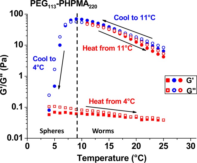
Storage (G′) and loss (G″) moduli recorded for a 10% w/w PEG113-PHPMA220 worm gel undergoing a temperature cycle between 25 and 4 °C (measurements were conducted at 1.0% strain and an angular frequency of 1.0 rad s–1).
Figure 9.
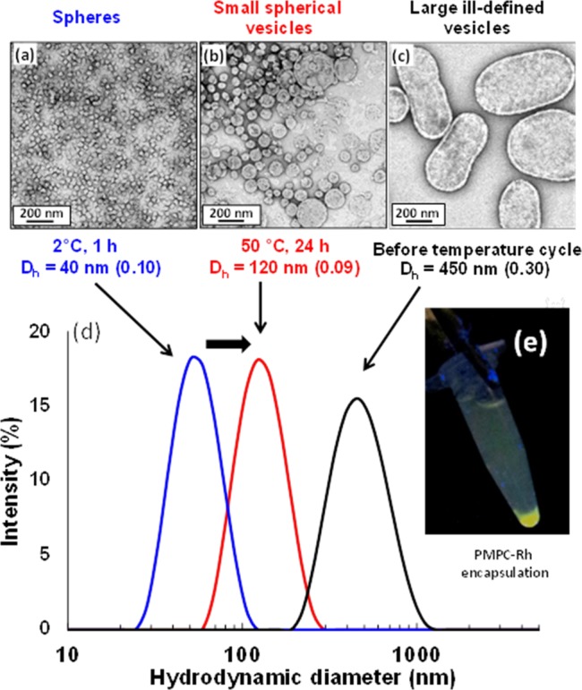
Effect of carrying out a temperature cycle on a 10% w/w dispersion of PEG113-PHPMA300 vesicles. TEM images obtained for (a) spherical micelles after cooling in ice for 1 h; (b) smaller vesicles after warming to 50 °C for 24 h; (c) large, polydisperse vesicles initially obtained after synthesis; (d) DLS size distributions obtained for the respective samples after dilution to 0.1% w/w; (e) centrifuge tube containing sedimented PEG113-PHPMA300 vesicles loaded with fluorescently poly[(2-methacryloyloxy)ethyl phosphorylcholine].
Conclusions
Well-defined PEG-based RAFT agents with high degrees of functionalization can be readily prepared by reacting monoaminated PEG chains with the activated ester of a commercially available carboxylic acid-functionalized RAFT agent. The resulting PEG macro-CTA can be used for the RAFT aqueous dispersion polymerization of HPMA at 50 °C. This relatively low temperature is preferred in view of the limited solubility of the PEG macro-CTA in hot aqueous solution. An optimized formulation using an AIPD initiator (PEG macro-CTA/AIPD = 3.0) afforded diblock copolymers with relatively low polydispersities and high blocking efficiencies, as judged by GPC analysis. High monomer conversions (>95%) were achieved in all cases and both TEM and DLS studies indicated that polymerization-induced self-assembly led to the generation of various PEGylated nano-objects, including spherical micelles, worms, or vesicles, depending on the precise synthesis conditions. A systematic approach enabled the elucidation of a detailed phase diagram for this new PEG113-PHPMAx diblock copolymer formulation. Interestingly, high copolymer concentrations (>17.5% w/w) and relatively long PHPMA blocks produced a remarkable range of nanostructures, including the first observation of oligolamellar vesicles formed during a PISA synthesis. SAXS studies allowed characterization of this new phase as well as some complex intermediate structures. In particular, detailed SAXS analysis indicates an average of three membranes per oligolamellar vesicle. SAXS also confirms the thermo-responsive nature of these PEG113-PHPMAx nano-objects, since partial fusion of spherical micelles can be induced by local heating caused by the synchrotron X-ray beam. Moreover, the PEG113-PHPMAx gels formed at above 10% w/w solids exhibit interesting rheological properties: unlike the previously reported PGMA-PHPMA formulation, the gel strength increases at lower temperatures, with a critical gelation temperature being observed on gradual cooling. This is presumably because branched structures and perforated bilayers are converted into linear worms. Subsequent warming to 40 °C causes a worm-to-vesicle transition, which results in degelation. Cooling of PEG113-PHPMA300 vesicles to 2 °C overnight induces a vesicle-to-sphere transition. Intriguingly, smaller, lower polydispersity vesicles are produced on warming to 50 °C. This thermal transition indicates a convenient loading mechanism for the in situ encapsulation of proteins or antibodies, which in turn suggests that such PEGylated nano-objects may have biomedical applications in the context of intracellular delivery. Finally, we note that the optimized RAFT aqueous dispersion polymerization protocol described herein offers a convenient and cost-effective synthetic route, since no postpolymerization processing or purification is required other than dialysis.
Acknowledgments
Svetomir Tzokov is thanked for carbon coating TEM grids. The authors are grateful to ESRF for providing beamtime. Diego Pontoni (PSCM) and the personnel of ID02 station is thanked for help with SAXS experiments. EPSRC is thanked for a Platform grant (EP/J007846/1) to support NJW. SPA thanks the European Research Council for an ERC Advanced Investigator grant (PISA 320372).
Supporting Information Available
Full experimental section and further characterization details for the monoaminated PEG113 precursor, the PEG113 macro-CTA, the SCPDB CTA, PEG113-PHPMAx block copolymers, and PEG113-PHPMAx nano-objects. Further rheology data and TEM images from temperature-dependent studies are also included. This material is available free of charge via the Internet at http://pubs.acs.org.
The authors declare no competing financial interest.
Supplementary Material
References
- Duncan R. Nat. Rev. Drug Discovery 2003, 2, 347–360. [DOI] [PubMed] [Google Scholar]
- Harris J. M.; Chess R. B. Nat. Rev. Drug Discovery 2003, 2, 214–221. [DOI] [PubMed] [Google Scholar]
- Jones M. W.; Mantovani G.; Blindauer C. A.; Ryan S. M.; Wang X.; Brayden D. J.; Haddleton D. M. J. Am. Chem. Soc. 2012, 134, 7406–7413. [DOI] [PubMed] [Google Scholar]
- Massignani M.; LoPresti C.; Blanazs A.; Madsen J.; Armes S. P.; Lewis A. L.; Battaglia G. Small 2009, 5, 2424–2432. [DOI] [PubMed] [Google Scholar]
- Alconcel S. N. S.; Baas A. S.; Maynard H. D. Polym. Chem. 2011, 2, 1442–1448. [Google Scholar]
- Brocchini S.; Godwin A.; Balan S.; Choi J.-w.; Zloh M.; Shaunak S. Adv. Drug Delivery Rev. 2008, 60, 3–12. [DOI] [PubMed] [Google Scholar]
- Cong Y.; Pawlisz E.; Bryant P.; Balan S.; Laurine E.; Tommasi R.; Singh R.; Dubey S.; Peciak K.; Bird M.; Sivasankar A.; Swierkosz J.; Muroni M.; Heidelberger S.; Farys M.; Khayrzad F.; Edwards J.; Badescu G.; Hodgson I.; Heise C.; Somavarapu S.; Liddell J.; Powell K.; Zloh M.; Choi J.-w.; Godwin A.; Brocchini S. Bioconjugate Chem. 2012, 23, 248–263. [DOI] [PubMed] [Google Scholar]
- Shaunak S.; Godwin A.; Choi J.-W.; Balan S.; Pedone E.; Vijayarangam D.; Heidelberger S.; Teo I.; Zloh M.; Brocchini S. Nat. Chem. Biol. 2006, 2, 312–313. [DOI] [PubMed] [Google Scholar]
- Ahmed F.; Discher D. E. J. Controlled Release 2004, 96, 37–53. [DOI] [PubMed] [Google Scholar]
- Ahmed F.; Pakunlu R. I.; Srinivas G.; Brannan A.; Bates F.; Klein M. L.; Minko T.; Discher D. E. Mol. Pharmaceutics 2006, 3, 340–350. [DOI] [PubMed] [Google Scholar]
- Cai S. S.; Vijayan K.; Cheng D.; Lima E. M.; Discher D. E. Pharm. Res. 2007, 24, 2099–2109. [DOI] [PubMed] [Google Scholar]
- Christian D. A.; Cai S.; Garbuzenko O. B.; Harada T.; Zajac A. L.; Minko T.; Discher D. E. Mol. Pharmaceutics 2009, 6, 1343–1352. [DOI] [PMC free article] [PubMed] [Google Scholar]
- Christie R. J.; Matsumoto Y.; Miyata K.; Nomoto T.; Fukushima S.; Osada K.; Halnaut J.; Pittella F.; Kim H. J.; Nishiyama N.; Kataoka K. ACS Nano 2012, 6, 5174–5189. [DOI] [PubMed] [Google Scholar]
- Matsumoto S.; Christie R. J.; Nishiyama N.; Miyata K.; Ishii A.; Oba M.; Koyama H.; Yamasaki Y.; Kataoka K. Biomacromolecules 2008, 10, 119–127. [DOI] [PubMed] [Google Scholar]
- Christie R. J.; Miyata K.; Matsumoto Y.; Nomoto T.; Menasco D.; Lai T. C.; Pennisi M.; Osada K.; Fukushima S.; Nishiyama N.; Yamasaki Y.; Kataoka K. Biomacromolecules 2011, 12, 3174–3185. [DOI] [PubMed] [Google Scholar]
- Chen W.; Zheng M.; Meng F.; Cheng R.; Deng C.; Feijen J.; Zhong Z. Biomacromolecules 2013, 14, 1214–1222. [DOI] [PubMed] [Google Scholar]
- Almgren M.; Brown W.; Hvidt S. Colloid Polym. Sci. 1995, 273, 2–15. [Google Scholar]
- Jørgensen E. B.; Hvidt S.; Brown W.; Schillén K. Macromolecules 1997, 30, 2355–2364. [Google Scholar]
- Duval M.; Waton G.; Schosseler F. Langmuir 2005, 21, 4904–4911. [DOI] [PubMed] [Google Scholar]
- Waton G.; Michels B.; Steyer A.; Schosseler F. Macromolecules 2004, 37, 2313–2321. [Google Scholar]
- Fernández V. V. A.; Tepale N.; Álvarez J. G.; Pérez-López J. H.; Macías E. R.; Bautista F.; Pignon F.; Rharbi Y.; Gámez-Corrales R.; Manero O.; Puig J. E.; Soltero J. F. A. J. Colloid Interface Sci. 2009, 336, 842–849. [DOI] [PubMed] [Google Scholar]
- Batrakova E. V.; Kabanov A. V. J. Controlled Release 2008, 130, 98–106. [DOI] [PMC free article] [PubMed] [Google Scholar]
- Battaglia G. In Nanotechnologies for the Life Sciences; Wiley-VCH Verlag GmbH & Co. KGaA: Hoboken, NJ, 2007. [Google Scholar]
- Blanazs A.; Armes S. P.; Ryan A. J. Macromol. Rapid Commun. 2009, 30, 267–277. [DOI] [PubMed] [Google Scholar]
- Discher D. E.; Eisenberg A. Science 2002, 297, 967–973. [DOI] [PubMed] [Google Scholar]
- LoPresti C.; Lomas H.; Massignani M.; Smart T.; Battaglia G. J. Mater. Chem. 2009, 19, 3576–3590. [Google Scholar]
- Wang X.; Guerin G.; Wang H.; Wang Y.; Manners I.; Winnik M. A. Science 2007, 317, 644–647. [DOI] [PubMed] [Google Scholar]
- Antonietti M.; Förster S. Adv. Mater. 2003, 15, 1323–1333. [Google Scholar]
- Israelachvili J. N.Intermolecular and Surface Forces; Academic Press: London, 1992. [Google Scholar]
- Nicolai T.; Colombani O.; Chassenieux C. Soft Matter 2010, 6, 3111–3118. [Google Scholar]
- Hayward R. C.; Pochan D. J. Macromolecules 2010, 43, 3577–3584. [Google Scholar]
- Charleux B.; Delaittre G.; Rieger J.; D’Agosto F. Macromolecules 2012, 45, 6753–6765. [Google Scholar]
- Blanazs A.; Madsen J.; Battaglia G.; Ryan A. J.; Armes S. P. J. Am. Chem. Soc. 2011, 133, 16581–16587. [DOI] [PubMed] [Google Scholar]
- Blanazs A.; Ryan A. J.; Armes S. P. Macromolecules 2012, 45, 5099–5107. [Google Scholar]
- Sugihara S.; Armes S. P.; Blanazs A.; Lewis A. L. Soft Matter 2011, 7, 10787–10793. [Google Scholar]
- Sugihara S.; Blanazs A.; Armes S. P.; Ryan A. J.; Lewis A. L. J. Am. Chem. Soc. 2011, 133, 15707–15713. [DOI] [PubMed] [Google Scholar]
- Wan W.-M.; Sun X.-L.; Pan C.-Y. Macromolecules 2009, 42, 4950–4952. [Google Scholar]
- Wan W.-M.; Sun X.-L.; Pan C.-Y. Macromol. Rapid Commun. 2010, 31, 399–404. [DOI] [PubMed] [Google Scholar]
- Boisse S.; Rieger J.; Belal K.; Di-Cicco A.; Beaunier P.; Li M.-H.; Charleux B. Chem. Commun. 2010, 46, 1950–1952. [DOI] [PubMed] [Google Scholar]
- Zhang X.; Boissé S. P.; Zhang W.; Beaunier P.; D’Agosto F.; Rieger J.; Charleux B. Macromolecules 2011, 44, 4149–4158. [Google Scholar]
- Chambon P.; Blanazs A.; Battaglia G.; Armes S. P. Macromolecules 2012, 45, 5081–5090. [Google Scholar]
- Blanazs A.; Verber R.; Mykhaylyk O. O.; Ryan A. J.; Heath J. Z.; Douglas C. W. I.; Armes S. P. J. Am. Chem. Soc. 2012, 134, 9741–9748. [DOI] [PubMed] [Google Scholar]
- Jones E. R.; Semsarilar M.; Blanazs A.; Armes S. P. Macromolecules 2012, 45, 5091–5098. [Google Scholar]
- Semsarilar M.; Jones E. R.; Blanazs A.; Armes S. P. Adv. Mater. 2012, 24, 3378–3382. [DOI] [PubMed] [Google Scholar]
- Sugihara S.; Sugihara K.; Armes S. P.; Ahmad H.; Lewis A. L. Macromolecules 2010, 43, 6321–6329. [Google Scholar]
- Zehm D.; Ratcliffe L. P. D.; Armes S. P. Macromolecules 2012, 46, 128–139. [Google Scholar]
- Boursier T.; Chaduc I.; Rieger J.; D’Agosto F.; Lansalot M.; Charleux B. Polym. Chem. 2011, 2, 355–362. [Google Scholar]
- dos Santos A. M.; Le Bris T.; Graillat C.; D’Agosto F.; Lansalot M. Macromolecules 2009, 42, 946–956. [Google Scholar]
- Rieger J.; Stoffelbach F. o.; Bui C.; Alaimo D.; Jérôme C.; Charleux B. Macromolecules 2008, 41, 4065–4068. [Google Scholar]
- Rieger G.; Osterwinter C.; Bui F. o.; Stoffelbach; Charleux B. Macromolecules 2009, 42, 5518–5525. [Google Scholar]
- Li Y.; Armes S. P. Angew. Chem., Int. Ed. 2010, 49, 4042–4046. [DOI] [PubMed] [Google Scholar]
- Westheimer F. Science 1987, 235, 1173–1178. [DOI] [PubMed] [Google Scholar]
- Elbert D. L.; Hubbell J. A. Biomacromolecules 2001, 2, 430–441. [DOI] [PubMed] [Google Scholar]
- Bartels J. W.; Cauet S. I.; Billings P. L.; Lin L. Y.; Zhu J. H.; Fidge C.; Pochan D. J.; Wooley K. L. Macromolecules 2010, 43, 7128–7138. [DOI] [PMC free article] [PubMed] [Google Scholar]
- Zheng Q.; Pan C.-Y. Macromolecules 2005, 38, 6841–6848. [Google Scholar]
- Skrabania K.; Miasnikova A.; Bivigou-Koumba A. M.; Zehm D.; Laschewsky A. Polym. Chem. 2011, 2, 2074–2083. [Google Scholar]
- Dormidontova E. E. Macromolecules 2001, 35, 987–1001. [Google Scholar]
- McCormick C. L.; Lowe A. B. Acc. Chem. Res. 2004, 37, 312–325. [DOI] [PubMed] [Google Scholar]
- Moad G.; Rizzardo E.; Thang S. H. Aust. J. Chem. 2005, 58, 379–410. [Google Scholar]
- Moad G.; Rizzardo E.; Thang S. H. Aust. J. Chem. 2009, 62, 1402–1472. [Google Scholar]
- Rizzardo E.; Chiefari J.; Chong B. Y. K.; Ercole F.; Krstina J.; Jeffery J.; Le T. P. T.; Mayadunne R. T. A.; Meijs G. F.; Moad C. L.; Moad G.; Thang S. H. Macromol. Symp. 1999, 143, 291–307. [Google Scholar]
- Madsen J.; Armes S. P.; Bertal K.; MacNeil S.; Lewis A. L. Biomacromolecules 2009, 10, 1875–1887. [DOI] [PubMed] [Google Scholar]
- Ratcliffe L. P. D.; Ryan A. J.; Armes S. P. Macromolecules 2013, 46, 769–777. [Google Scholar]
- Rosselgong J.; Armes S. P. Macromolecules 2012, 45, 2731–2737. [Google Scholar]
- Rosselgong J.; Armes S. P.; Barton W.; Price D. Macromolecules 2009, 42, 5919–5924. [Google Scholar]
- Rosselgong J.; Armes S. P.; Barton W. R. S.; Price D. Macromolecules 2010, 43, 2145–2156. [Google Scholar]
- Verber R.; Blanazs A.; Armes S. P. Soft Matter 2012, 8, 9915–9922. [Google Scholar]
- Jain S.; Bates F. S. Science 2003, 300, 460–464. [DOI] [PubMed] [Google Scholar]
- Chen L.; Shen H.; Eisenberg A. J. Phys. Chem. B 1999, 103, 9488–9497. [Google Scholar]
- Rank A.; Hauschild S.; Förster S.; Schubert R. Langmuir, 2009, 25, 1337–1344. [DOI] [PubMed] [Google Scholar]
- Pedersen J. S. J. Chem. Phys. 2001, 114, 2839–2846. [Google Scholar]
- Pedersen J. S.; Gerstenberg M. C. Colloids Surf., A 2003, 213, 175–187. [Google Scholar]
- Feigin L. A. and Svergun D. I.. Structure Analysis by Small-Angle X-Ray and Neutron Scattering; Plenum Press: New York, 1987. [Google Scholar]
- Ilavsky J.; Jemain P. R. J. App. Cryst. 2009, 42, 347–353. [Google Scholar]
- Takahashi Y.; Tadokoro H. Macromolecules 1973, 6, 672–675. [Google Scholar]
- Fetters L. J.; Lohse D. J.; Richter D.; Witten T. A.; Zirkel A. Macromolecules 1994, 27, 4639–4647. [Google Scholar]
- Kohlbrecher J., Bressler I.SASfit; Paul Scherrer Institute: Switzerland, 2008; https://kur.web.psi.ch/sans1/SANSSoft/sasfit.html.
- Kholodenko A. L. Macromolecules 1993, 26, 4179–4183. [Google Scholar]
- Navas B. P.; Lohner K.; Deutsch G.; Sevcsik S.; Riske K. A.; Dimova R.; Garidel P.; Pabst G. Biochim. Biophys. 2005, 1716, 40–48. [DOI] [PubMed] [Google Scholar]
- Pabst G.; Koschuch R.; Pozo-Navas B.; Rappolt M.; Lohner K.; Laggner P. J. Appl. Crystallogr. 2003, 36, 1378–1388. [Google Scholar]
- Garamus V. M.; Pedersen J. S.; Kawasaki H.; Maeda H. Langmuir 2000, 16, 6431–6437. [Google Scholar]
- Battaglia G.; Ryan A. J. J. Am. Chem. Soc. 2005, 127, 8757–8764. [DOI] [PubMed] [Google Scholar]
- Battaglia G.; Ryan A. J. Nat. Mater. 2005, 4, 869–876. [DOI] [PubMed] [Google Scholar]
- Battaglia G.; Ryan A. J. Angew. Chem., Int. Ed. 2006, 45, 2052–2056. [DOI] [PubMed] [Google Scholar]
- Braun J.; Bruns N.; Pfohl T.; Meier W. Macromol. Chem. Phys. 2011, 212, 1245–1254. [Google Scholar]
- Madsen J.; Warren N. J.; Armes S. P.; Lewis A. L. Biomacromolecules 2011, 12, 2225–2234. [DOI] [PubMed] [Google Scholar]
- LoPresti C.; Massignani M.; Fernyhough C.; Blanazs A.; Ryan A. J.; Madsen J.; Warren N. J.; Armes S. P.; Lewis A. L.; Chirasatitsin S.; Engler A. J.; Battaglia G. ACS Nano 2011, 5, 1775–1784. [DOI] [PubMed] [Google Scholar]
Associated Data
This section collects any data citations, data availability statements, or supplementary materials included in this article.


