Abstract
Fluorescence molecular tomography (FMT), as a promising imaging modality, can three-dimensionally locate the specific tumor position in small animals. However, it remains challenging for effective and robust reconstruction of fluorescent probe distribution in animals. In this paper, we present a novel method based on sparsity adaptive subspace pursuit (SASP) for FMT reconstruction. Some innovative strategies including subspace projection, the bottom-up sparsity adaptive approach, and backtracking technique are associated with the SASP method, which guarantees the accuracy, efficiency, and robustness for FMT reconstruction. Three numerical experiments based on a mouse-mimicking heterogeneous phantom have been performed to validate the feasibility of the SASP method. The results show that the proposed SASP method can achieve satisfactory source localization with a bias less than 1mm; the efficiency of the method is much faster than mainstream reconstruction methods; and this approach is robust even under quite ill-posed condition. Furthermore, we have applied this method to an in vivo mouse model, and the results demonstrate the feasibility of the practical FMT application with the SASP method.
OCIS codes: (100.3010) Image reconstruction techniques, (100.3190) Inverse problems, (110.6955) Tomographic imaging, (170.3660) Light propagation in tissues, (170.3880) Medical and biological imaging, (290.1990) Diffusion, (290.7050) Turbid media
1. Introduction
With the solid development of fluorescent probes and reporter technologies [1], the application of fluorescence molecular imaging in biomedical study has become a hot spot over the past few years [2, 3]. It offers an opportunity for noninvasive visualization of biological processes at the cellular and molecular levels. Fluorescence molecular tomography (FMT) is a new promising imaging modality, which can three-dimensionally detect fluorescence biodistribution in vivo, therefore greatly facilitate its applications in small-animal research and pre-clinical diagnostics [4, 5].
However, it is challenging for FMT to reconstruct the fluorescence biodistribution effectively and robustly [6], because FMT presents a challenging inverse problem which is quite ill-posed or ill-conditioned due to the following three reasons [6, 7]:
-
1.
Photons emitted from the fluorescent sources undergo multiple scattering and potential absorption in biological tissues.
-
2.
Only the photon distribution on the surface is measurable. Although increase of the measurement data sets can reduce the ill-posedness, the problem may still be ill-conditioned as it is too sensitive to noise caused by charge-coupled-device (CCD) measurement errors and data discretization errors.
-
3.
Furthermore, the high sampling measurements and the real animal-shape geometry modeling usually produce a large amount of data, which lead to large computational complexity and big storage capacity.
Therefore, the FMT reconstruction faces various challenges on its efficiency and robustness, and the development of feasible FMT reconstruction approaches plays a unique role in the achievement of practical biomedical applications.
In order to overcome the above challenging problems, some researchers have proposed various regularization methods to make the solution stable and insensitive to noise. Among different regularization methods, the Tikhonov regularization is one of the most popular regularization methods and has been widely applied in resolving FMT problems [8, 9]. It adds an L2-norm constraint of the solution to the original problem, and aims to reduce high-frequency noise in the reconstructed results. The primary benefit of using Tikhonov regularization is that the optimization problem can be simplified and efficiently solved by using standard minimization tools, such as the conjugate gradient method and Newton method. However, it tends to produce an over-smooth solution and loss of some localized features during the reconstruction process by using Tikhonov regularization [10].
In order to improve the quality of the reconstruction for FMT, more a priori information should be included [6, 11]. Over the past few years, considerable attention has been focused on the sparse regularization being used in the field of compressed sensing (CS) for signal recovery and image processing. According to the CS theory, a sparse or compressive signal can be faithfully recovered from far fewer samples or measurements [12]. Considering that in the practical applications of FMT, the fluorescent sources are usually sparse because the fluorescent probes used in FMT are designed to locate the specific areas of interest such as tumors or cancerous tissues, which are usually small and sparse compared to the entire reconstruction domain [13]. Hence, the problem of FMT can be regarded as a sparse reconstruction problem and the fluorescent source distribution can be recovered by using sparse-type regularization (L0-norm and L1-norm) strategies. Inspired by the ideas behind the CS theory, several algorithms incorporated with L1-norm regularization have been proposed to solve the optical tomography problems in recent years [10, 13–17]. To preserve the sparsity of the fluorescent sources, an iteratively reweighted scheme based approach, which was able to obtain more reasonable and satisfactory results compared with the Tikhonov method was proposed [14]. At the same time, to improve the reconstruction accuracy, an effective FMT reconstruction algorithm based on the iterated shrinkage method with the L1-norm (IS_L1) was proposed [15], the reconstruction algorithm was able to comparatively acquire accurate results even with quite limited measurement data sets. However, the approximate convergence rate of this algorithm is linear since it is a first-order method [16]. Therefore, it needs a large number of iterations to reach an acceptable solution, especially when the dimension of the FMT inverse problem is quite large. To enhance the reconstruction efficiency, the stagewise orthogonal matching pursuit (StOMP) based method was introduced to conserve computation time due to the greedy pursuit strategy [17], while it needs to estimate the sparsity factor which indicates the number of unknowns in advance. There are different sparsity factors for different FMT experiments, therefore it is not always able to achieve acceptable results for estimation of the sparsity factor empirically in this method. Although the aforementioned reconstruction methods usually work well in some specific and highly controlled situation, further study is urgently needed to investigate more general cases [18].
In this paper, a novel method based on the sparsity adaptive subspace pursuit (SASP) has been proposed for FMT reconstruction. This novel method adopts a subspace projection and correlation maximization approach to simplify the FMT problem with sparsity-promoting L1-norm regularization and to treat it as the basis pursuit problem [19]. The proposed method performs reconstruction by employing a search strategy in which a number of K (i.e., the sparsity factor which indicates the number of unknowns) vectors with the highest correlation are selected from the candidate set. Then the search strategy updates the current supporting set by merging the newly selected vector set. During each iteration step, a bottom-up approach is presented to estimate and update the sparsity factor adaptively and heuristically instead of determining it manually or empirically. In addition, our method incorporates an effective technique for re-evaluating the reliability of all candidates at each iteration of the process, which guarantees the accuracy and reliability for fluorescence reconstruction. To better evaluate the proposed method, we compared it to the IS_L1 method and the StOMP method both in numerical experiments and in vivo mouse experiments [15, 17]. The proposed method is proved to be more accurate, efficient, robust, and reliable for fluorescence reconstruction compared to the contrasting methods, which demonstrates its potential for practical FMT applications.
The outline of the paper is listed as following. In section 2, we present the reconstruction methodology for FMT. In the beginning, the diffusion approximation for the radiative transfer equation is brieñy introduced. Then, the adaptive sparsity subspace pursuit based reconstruction method is elaborately formulated. In section 3, numerical phantom experiments of the proposed method are performed. In section 4, experimental mouse reconstruction in heterogeneous tissue further demonstrates the robustness and feasibility of this proposed method. In section 5, we discuss relative issues and conclude our work.
2. Method
2.1 Photon propagation model
Describing photon propagation in biological tissues can be modeled using the integro-differential equation known as the radiative transfer equation (RTE) [20]. However, it is a major endeavor to provide solutions for the RTE and it remains a challenging task in the fields of tissue optics and radiological sciences [21]. For photon propagation in biological tissues within the near-infrared spectral window, scattering is the dominant phenomenon over absorption. Therefore, the diffusion equation (DE) as a low-order approximation of the RTE is usually used to model the photon transport in highly scattering media [22, 23]. For steady-state FMT with point excitation sources, the following coupled diffusion equations are widely used as an effective model for photon propagation [23, 24]:
| (1) |
where Ω denotes the domain of the problem; subscripts x and m denote the excitation and emission wavelengths respectively, is the photon flux density for excitation (subscript x) and fluorescent light (subscript m); denotes the absorption coefficient of the tissue and denotes the diffusion coefficient; denotes the scattering coefficient; and g denotes the anisotropy parameter [25]. is the fluorescent yield to be reconstructed which incorporates the quantum efficiency η and absorption coefficient of the fluorescent probe. Here, we assume that the absorption and scattering of the excitation light caused by the fluorescent probes will have little effect on the distribution of , because the fluorescent probes usually occupy a very small space compared to domain Ω. represents the different excitation point source positions with the amplitude Θ. For FMT with point illumination, a collimated laser spot is usually modeled as an isotropic point source , where is the point one transport mean free path into the medium from the illumination spot; Θ is the amplitude of the point source; and is the Dirac function.
In order to solve the coupled equations, the Robin-type boundary conditions (RBC) are implemented on the boundary of domain Ω [25]:
| (2) |
where denotes the outward normal vector to the surface . q is a constant that is approximated as . R is a parameter governing the internal reflection at the boundary .
2.2 Linear relationship establishment
A finite element method is used to calculate solutions of the diffusion Eqs. (1) together with the boundary condition (2). We discretize the domain with small tetrahedrons and take the base functions as the test functions. Then, the FMT problem can be linearized and the following matrix-form equations can be obtained:
| (3) |
| (4) |
with
where and denote the base function of node i and node j, respectively; denotes the system matrix for excitation (subscript x) and emission (subscript m); and denotes the excitation source distribution after discretization. Matrix G is obtained by discretizing the unknown fluorescent yield distribution, while vector X is the fluorescent yield yet to be reconstructed.
For each excitation point source at during the excitation process, the photon density , which is used as the energy source for the emission process, can be obtained by solving Eq. (3). Considering that is symmetrical and positive definite, Eq. (4) can be formulated into the following matrix-form equation:
| (5) |
The reconstruction of the fluorescent yield is to recover vector X from the measured photon density on in the continuous wave (CW) mode, so can be partitioned into measurable boundary values and immeasurable interior values . By removing the immeasurable entries in and the corresponding rows in , we have
| (6) |
Then, we assemble Eq. (6) for different excitation positions and obtain the following Matrix-form equation:
| (7) |
More background and details can be found in [4, 7, 26, 27].
Hence the linear relationship between the measured photon density distribution and the unknown fluorescent source distribution has been established, and can improve computational efficiency. It is worth mentioning that Eq. (7) is an underdetermined system of linear equations because the available surface photon density distribution is far more limited than the unknown internal fluorescent source distribution, which causes difficulties in the following tomographic reconstruction.
2.3 Reconstruction based on adaptive sparsity subspace pursuit
The reconstruction for FMT is involved in solving an underdetermined system of linear equations. As mentioned above, because tumors are small and sparse compared to the entire reconstruction domain in earlier detection, the fluorescent sources, which indicate the distribution of tumors, are usually sparse. This can be considered as a kind of a priori information of the fluorescent sources. Here, the L1 regularization is incorporated into the FMT problem to promote the sparsity of the solution, and Eq. (7) is transformed into the one-norm regularized least-squares problem:
| (8) |
where λ is a regularization parameter which is used to govern the sparsity of the solution: larger values typically produce sparser results. Here, if the columns of matrix A are regarded as a set of atoms coming from an available dictionary and vector X is regarded as the coefficient vector, the FMT problem can be considered as the basis pursuit problem and has the form as follows:
| (9) |
In this case, the optimal solution of Eq. (9) is expected to be a sparse solution (i.e., solution where only a small number of entries are nonzero). The SASP method aims to achieve a sparse solution to the FMT problem. Next, we will describe its basic ingredients.
In the SASP method, some innovative strategies including subspace projection, the bottom-up sparsity adaptive approach, and backtracking technique are applied to enhance the reconstruction accuracy and robustness. The main steps of the proposed algorithm are summarized below.
| Algorithm 1 Sparsity Adaptive Subspace Pursuit Algorithm | |||
|---|---|---|---|
| Input: Matrix A, Vector Φ, Threshold σ, The maximum number of iterations | |||
| Initialization:, , , | |||
| n = 1 | |||
| (1) | |||
| (2) K indices corresponding to the largest magnitude entries in vector }. | |||
| (3) | |||
| (4) | |||
| Iteration(): | |||
| (1) | |||
| (2) K indices corresponding to the largest magnitude entries in vector } | |||
| (3) | |||
| (4) K indices with the largest magnitude entries of projection coefficients } | |||
| (5) | |||
| (6) Update the sparsity factor K | |||
| 1) if then | |||
| , , | |||
| 2) else | |||
| The sparse factor Kstays the same, , | |||
| end if | |||
| (7) if halting condition true (i.e., or ), then quit the iteration | |||
| Output: | |||
| The sparse solution to the FMT problem , satisfying and . | |||
The SASP method is a heuristic method. It starts with an empty index set and initial residual vector . The sparsity factor K and the step size S are also initialized. To further illustrate how such a method fits into FMT reconstruction, we mathematically derive the SASP method using the following five steps.
Step I
To make the candidate set of the proposed method by using the maximal correlation test, assuming that within an individual iteration of optimization, we have the (n-1)th estimate for the residual vector . Then, the n-th iteration applies matched filtering to the current residual vector, getting a vector of residual correlations to be:
| (10) |
which can be considered as a measure of the correlations between the atoms in system matrix A and the current residual vector. Then, we select K indices corresponding to the largest magnitude entries in the residual correlations vector and merge them with the support set estimated in the previous iteration, thereby yielding the candidate set:
| (11) |
Step II
To form the true support set of the proposed method, we introduce the subspace projection approach and the backtracking technique. Next, the observation vector Φ is projected onto the subspace spanned by the columns of , where denotes the submatrix of A with indices from the candidate set . The projection of Φ onto span() is defined as
| (12) |
where denotes the pseudo-inverse of matrix . We can see that the subspace projection coefficients equal
| (13) |
It can be regarded as a new approximation of the sparse solution of the FMT problem. The procedure selects K indices with the largest correlation magnitudes of to form the new support set:
| (14) |
where I is the new support set estimated in this iteration.
Step III
To determine whether the new support set is well suited to build the sparse solution of the FMT problem, we need to calculate the new residual. We then perform projection of the observations Φ onto the subspace spanned by the columns of A belonging to the new support set I. Let denote the submatrix with columns chosen using index set I, we have
| (15) |
Then, the updated residual is computed as:
| (16) |
Suppose A is an high dimensional dense matrix, then computing has high computational complexity. By exploring the subspace projection strategy and the backtracking technique, the computational complexity of r can be greatly reduced because there are only K columns in , which is only a small fraction of the original system matrix A.
Step IV
To estimate the optimal sparsity factor of the fluorescent sources, the proposed method adopts a sparsity adaptive strategy, which alternatively estimates the sparsity and the true support set of the fluorescent sources.
Here, an adaptive one-dimensional search approach is used to get the optimal sparsity factor K according to the changes from the previous residual to the new residual r. If the norm of r is smaller than that of , the current sparsity factor K is considered to be suitable for the reconstruction process in the current iteration and doesn’t need to be changed. The residual and the true support set , which can be used in the next iteration, are replaced by the newly estimated residual r and support set I respectively. Otherwise, the sparsity factor is estimated to be smaller than the real case, and it is updated by adding the step size S, i.e., the new sparsity factor is set as K = K + S. In addition, the residual and true support set are replaced by the previous residual and , ensuring that the newly generated residual is the minimal residual until the current iteration.
Step V
This step is used to determine whether or not it is time to discontinue this proposed method. There are many halting conditions for practical FMT reconstruction methods. One common approach is to stop the method when the norm of the current residual is below a certain threshold value. Another approach is to end the method when the relative residue improvement between two consecutive iterations was below a certain threshold, because it is not worth it to take more costly iterations if the resulting improvement is too small. In this paper, we suggest that the SASP method is finished when the norm of the residual is smaller than the threshold σ or the maximum iteration number is reached. In our following experiments, the parameters σ and were optimized according to experimental experience. The threshold σ was set to equal , where denoted the Euclidean length of the observation vector Φ. In our experiments, the proposed method was good enough to obtain satisfactory results when using as the value of the threshold parameter σ. The maximum iteration number was set to be 25. In our experiments, all the reconstructions with the proposed method stopped within 25 iterations.
We check the halting conditions and, if it is not yet ready to stop, we set and go to the next iteration of the SASP method. In the next iteration, the updated sparsity factor K and residual will be employed. If it is time to stop, the current support set is good enough to build the sparse solution of the FMT problem. We then output the estimated sparse solution , satisfying and , where N denotes the length of .
To better understand the proposed reconstruction method in our study, further instructions on the backtracking technique are given.
The backtracking technique: Note that there are 2K indices in the candidate set , among which some of them do not belong to the correct support set. In Step II of the SASP method, a backtracking strategy is adopted to expurgate those indices from and form the new support set I. This backtracking strategy is quite important as it enables the method to re-evaluate the reliability of all candidates at each iteration of the process, and it can remove the indices that do not belong to the current support set and are added in the previous iteration. Those indices are thought to be right in the previous iteration, but they are thought to be wrong in the current iteration. If some of the removed indices belong to the final support set of the reconstruction method, they will be added to the support set in the following iterations. The backtracking strategy will make the method more robust and make the reconstruction results more accurate. There is a big difference between the StOMP method and the SASP method because the former one generates a list of candidates sequentially, without backtracking. This difference makes the SASP method more reliable than the StOMP method.
3. Numerical experiments and results
In this section, numerical results were presented to demonstrate the feasibility of the proposed reconstruction method. The numerical experiments were performed based on a mouse-mimicking heterogeneous phantom, as shown in Fig. 1 . The phantom was a cylinder, which was 20mm in diameter and 20mm in height, consisting of four kinds of materials to represent muscle (M), lungs (L), heart (H), and bone (B). The optical parameters of each kind of materials for both the excitation and emission wavelength are listed in Table 1 [27–29]. Figure 1(a) demonstrates a 3D view of the phantom which was discretized into 3756 nodes and 21715 tetrahedral elements using the finite-element method and Fig. 1(b) demonstrates the cross-section of the phantom in the z = 0 plane. The black dots in Fig. 1(b) represent the excitation light sources, which were modeled as isotropic point sources placed at a depth of one transport mean free path beneath the surface in the z = 0 plane. Fluorescence measurement was conducted in transillumination mode. For each excitation source, the emitted fluorescence was measured from the opposite side of the cylindrical phantom with a 160° field of view (FOV), which is illustrated in Fig. 1(b). As mentioned above, the fluorescent sources are usually quite small and sparse for FMT, so, we used small spheres with a diameter of 2mm centered in the z = 0 plane to represent the fluorescent sources. Figure 2 demonstrates three different phantom setups under the situation of single, double and triple sources respectively. The first row of Fig. 2(a), 2(b), 2(c) shows the 3D views of the phantom setups and the second row of Fig. 2(d), 2(e), 2(f) shows the corresponding slice images in the z = 0 plane. The fluorescent yields of the sources were all set to be 0.6 mm−1. The finite element method was used to solve the forward model and the measurements on the surface of the phantom were collected [27, 29]. Considering that in practical FMT experiments using a CCD camera, the shot noise always exists. When large numbers of photons are collected, the noise will approach a Gaussian distribution. We added 5% Gaussian noise to simulate the real case.
Fig. 1.
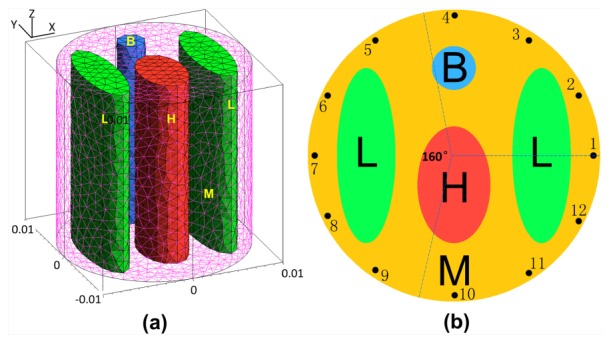
A mouse-mimicking heterogeneous cylindrical phantom. Each kind of tissue material is labeled by a letter, B for Bone, L for lungs, H for heart, and M for muscle. (a) 3D view of the phantom. (b) Cross-section of the phantom in the z = 0 plane.
Table 1. Optical parameters of the heterogeneous phantom.
| Material | ||||
|---|---|---|---|---|
| Bone | 0.0024 | 1.75 | 0.0035 | 1.61 |
| Lungs | 0.0133 | 1.97 | 0.0203 | 1.95 |
| Heart | 0.0083 | 1.01 | 0.0104 | 0.99 |
| Muscle | 0.0052 | 1.08 | 0.0068 | 1.03 |
Fig. 2.
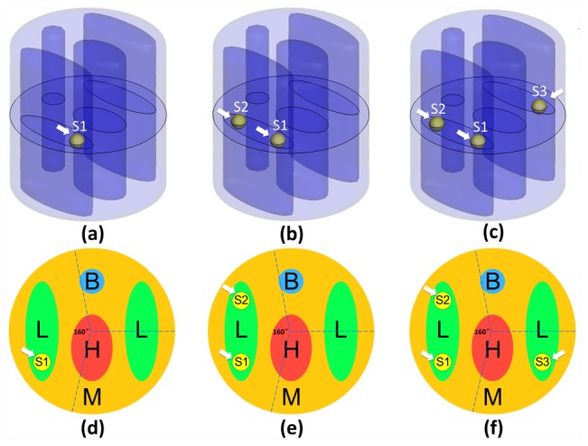
Three different phantom setups under the situation of single (a, d), double (b, e), and triple (c, f) sources respectively. The first row (a, b, c) shows the 3D views of the phantom setups and the second row (d, e, f) shows the corresponding slice images in the z = 0 plane. All of the fluorescent sources were set to be spherical and centered in the z = 0 plane. The diameters of these fluorescent sources were all set to be 2mm. Arrows in a-f indicate corresponding locations of the sources. S1, S2, and S3 respectively, denote the Source No of the first source, the second source and the third source in the tissue material of the lungs.
In this paper, in order to better evaluate the proposed method, we compared it with the IS_L1 method and the StOMP method. The second reconstruction method of the two contrast methods was adopted as it used a greedy pursuit strategy. For the proposed method, the step size S was set to 2. For the IS_L1 method, the regularization parameter was set to 2e−5. For the StOMP method, the parameter α was set to 0.8 and the parameter was set to 100, which were the same as the values used by D. Han et al. [17]. For all of the reconstruction methods, the zero vector was used as the initial value of the solution. All of the reconstructions were performed on our desktop computer with 2.39 GHz Intel Core 2 Duo CPU and 2GB RAM.
3.1 Experiment 1——evaluation of reconstruction accuracy
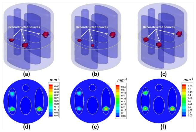
In the first experiment, we reconstructed fluorescent sources with different numbers to evaluate the reconstruction accuracy of the proposed method. Three different phantom setups for single, double and triple sources were used, as presented in Fig. 2. The fluorescence was excited by point sources from 12 different locations in sequence, as presented in Fig. 1(b). Every 30°, measurements of emission fluorescence were taken in the transillumination mode, then, a total number of 12 data sets were collected to perform the reconstruction of the fluorescent yield. In order to simulate the real case, 5% Gaussian noise was added to the measurement data sets. The actual fluorescence yield was set as 0.6 mm−1. To validate the reconstruction accuracy of the proposed method, we compared it to the IS_L1 method and StOMP method. Figures 3 , 4 and 5 give the reconstruction results for three different phantom setups, demonstrating the 3D view of the reconstructed sources in the phantom setups and the slice images in the z = 0 plane. The red circles in the slice images denote the real locations of the fluorescent sources. As shown in Figs. 3, 4 and 5, the stable locations of the fluorescent sources can be obtained through IS_L1 method, but the maximum values of the reconstructed fluorescent yield were smaller than those of the StOMP method and the SASP method. The StOMP method could acquire acceptable results when only one or two fluorescent sources existed. However, when three fluorescent sources existed, the reconstruction results were not satisfactory. Based on the data in Fig. 5(b) and Fig. 5(e), the fluorescent yield of the two sources on the left side (i.e., Source S1 and S2) was not well reconstructed. The reason for this result may be that the StOMP method didn’t adopt a sparsity adaptive strategy to achieve the optimal sparsity factor of the fluorescent sources and the choices of threshold parameters α and were estimated before the reconstruction process started and mainly came from experience. The proposed method could obtain satisfactory reconstruction results in three cases. These more accurate results benefited from the backtracking strategy and sparsity adaptive strategy. To analyze the reconstruction accuracy quantitatively, we defined the relative intensity error to be , where denotes the true fluorescent yield of the source and denotes the maximum reconstructed value of the fluorescent yield. We also defined the location error to be , where denotes the true location of the source center and denotes the location of the finite element node with the maximum reconstructed value of the fluorescent yield for that source. Table 2 summarizes the results of the quantitative analysis of different reconstruction methods. As shown in Table 2, all the three reconstruction methods could acquire satisfactory source localizations; however, the relative intensity errors of the proposed method were smaller. Figure 6(a) shows the relationship curve between sparsity factor K and iteration step n with a different number of sources. The sparsity factor K was updated automatically according to the changes of the residual between two consecutive iterations. Simultaneously, the residual was reduced to a small value, as shown in Fig. 6(b). If the residual was below , the relative residual decrement between two consecutive iterations became too small and we thought it was not worth to take more costly iterations.
Fig. 3.
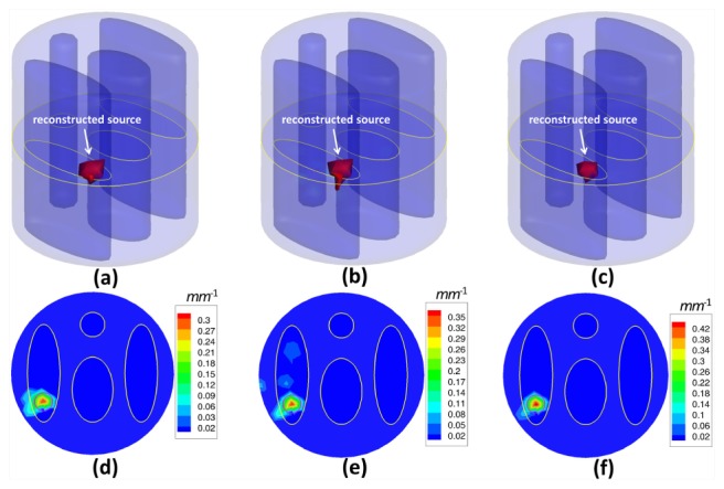
Fluorescent yield reconstruction results by the IS_L1 method (a, d), the StOMP method (b, e) and the proposed method (c, f) for a single spherical fluorescent source and 12 measurement data sets corrupted by 5% Gaussian noise. The first row (a, b, c) shows the 3D views of the reconstruction results and the second row (d, e, f) shows the corresponding slice images in the z = 0 plane. The red circles in the slice images denote the real locations of the fluorescent sources.
Fig. 4.
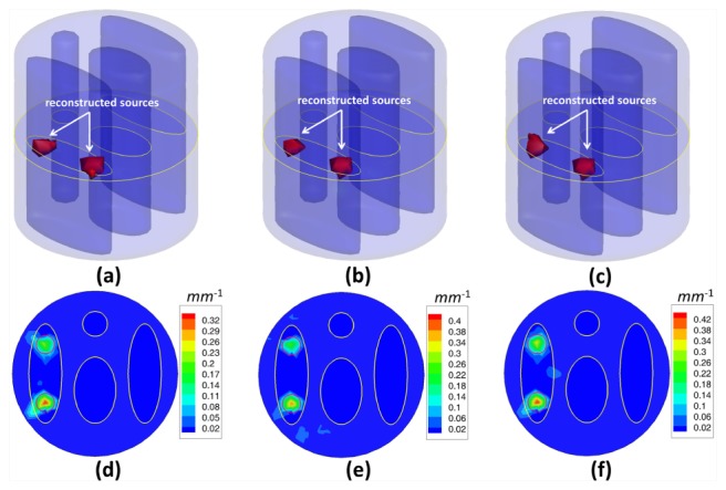
Fluorescent yield reconstruction results by the IS_L1 method (a, d), the StOMP method (b, e) and the proposed method (c, f) for the double spherical fluorescent sources and 12 measurement data sets corrupted by 5% Gaussian noise. The first row (a, b, c) shows the 3D views of the reconstruction results and the second row (d, e, f) shows the corresponding slice images in the z = 0 plane. The red circles in the slice images denote the real locations of the fluorescent sources.
Fig. 5.
Fluorescent yield reconstruction results by the IS_L1 method (a, d), the StOMP method (b, e) and the proposed method (c, f) for triple spherical fluorescent sources and 12 measurement data sets corrupted by 5% Gaussian noise. The first row (a, b, c) shows the 3D views of the reconstruction results and the second row shows the corresponding slice images in the z = 0 plane. The red circles in the slice images denote the real locations of the fluorescent sources.
Table 2. Quantitative analysis of the reconstruction accuracy from the results of the IS_L1 method, the StOMP method and the proposed method for 12 measurement data sets corrupted by 5% Gaussian noise.
| Phantom setup | Source No. | Location error (mm) (IS_L1) | Location error (mm) (StOMP) | Location error (mm) (SASP) | Relative intensity error (IS_L1) | Relative intensity error (StOMP) | Relative intensity error (SASP) |
|---|---|---|---|---|---|---|---|
| 1 source | S1 | 0.096 | 0.096 | 0.096 | 46.78% | 37.63% | 20.47% |
| 2 sources | S1 | 0.096 | 0.096 | 0.096 | 43.09% | 32.28% | 25.06% |
| S2 | 0.371 | 0.371 | 0.371 | 57.25% | 47.31% | 37.28% | |
| 3 sources | S1 | 0.096 | 0.096 | 0.096 | 44.97% | 60.73% | 20.20% |
| S2 | 0.371 | 0.371 | 0.371 | 64.03% | 53.43% | 12.90% | |
| S3 | 0.148 | 0.148 | 0.148 | 24.71% | 4.20% | 4.60% |
Fig. 6.
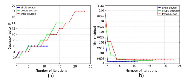
The relationship curves as a function of iteration steps with a different number of sources. (a) The relationship curve between sparsity factor K and iteration n. (b) The relationship curve between residual and iteration n.
3.2 Experiment 2——evaluation of reconstruction efficiency
To examine the reconstruction efficiency of the proposed method, we also compared it with the IS_L1 method and the StOMP method, which were two mainstream methods for FMT reconstruction. This numerical experiment was performed using a mouse-mimicking heterogeneous cylindrical phantom which contained three sources, as presented in Fig. 2 (c, f). To better evaluate the time cost of these reconstruction methods, we conducted the numerical experiment on five kinds of volumetric meshes of different sizes. For all these reconstruction methods, the zero vector was used to initialize the unknowns. The comparison of the reconstruction efficiency was made based on the data in Table 3 . It showed the time consumed by the proposed method as well as the two other methods compared for reconstructing the five groups of data sets whose sizes were determined by the density of the discrete volumetric mesh. Each value of the reconstruction time was the average of ten independent runs. All three reconstruction methods were coded in MATLAB and performed on our desktop computer with 2.39 GHz Intel Core 2 Duo CPU and 2GB RAM.
Table 3. The comparison of the reconstruction efficiency based on different methods. The size of the volumetric mesh equals the number of nodes multiplied by the number of tetrahedral elements.
| No. | Volumetric mesh size | IS_L1 (s) | StOMP (s) | SASP (s) |
|---|---|---|---|---|
| 1 | 2133 × 12010 | 33.3594 | 2.2813 | 1.5938 |
| 2 | 2970 × 16877 | 66.1875 | 3.7031 | 2.4375 |
| 3 | 3756 × 21715 | 88.0156 | 5.5156 | 3.2188 |
| 4 | 4650 × 26722 | 116.3750 | 7.7188 | 4.2969 |
| 5 | 5255 × 30393 | 140.8125 | 8.8438 | 4.8594 |
The results revealed that: 1. When reconstructing the same data set, the StOMP method worked more efficiently than the IS_L1 method, but was less efficient than the proposed SASP method; 2. When the size of the data set was increased, the SASP method became more computationally competitive; 3. All of the data sets were discretized based on the mouse-mimicking heterogeneous phantom with three sources in the tissue material of the lungs (L) (Fig. 2 (c, f)), which implied that the proposed method was not only time efficient but also potential for practical FMT applications.
3.3 Experiment 3——evaluation of reconstruction robustness of limited measurement data
To verify the reconstruction robustness of the proposed method, the amount of measurement data was reduced and the reconstruction of the fluorescent sources was conducted, simulating a much worse case scenario. This is quite necessary because long-term measurement is not appropriate or feasible in some cases of practical FMT experiments. For example, when imaging small animals such as mice or rabbits, the bleaching effect of the fluorescent probe caused by long-term measurement must be taken into consideration, as it can affect the experimental results. To resolve this problem, it is necessary to reduce the amount of fluorescence measurements and reconstruct the fluorescent sources from quite limited measurement data. Here, only the measurement data sets generated by excitation point sources 1, 4, 7 and 10 were retained by us, as shown in Fig. 1(b). In other words, we conducted the reconstruction from only four measurement data sets corrupted by 5% Gaussian noise. A mouse-mimicking heterogeneous cylindrical phantom with three sources was used to perform the numerical experiment, as shown in Fig. 2(c), 2(f). Figure 7 presents the reconstruction results from four measurement data sets, demonstrating the 3D views of the reconstructed sources in the phantoms and the corresponding slice images in the z = 0 plane. The location errors of the reconstruction results, as well as the relative intensity errors, are summarized in Table 4 .
Fig. 7.
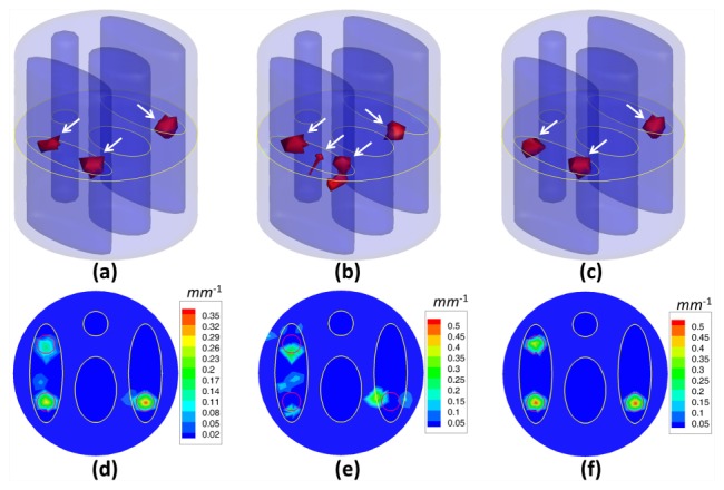
Reconstruction results from the IS_L1 method (a, d), the StOMP method (b, e) and the proposed method (c, f) for 3 spherical fluorescent sources and 4 measurement data sets corrupted by 5% Gaussian noise. These results are presented in the form of iso-surfaces for 30% of the maximum value (a, b, c) and slice images in the z = 0 plane (d, e, f). The red circles in the slice images denote the real positions of the fluorescent sources. The white arrows in a-c indicate the locations of the reconstructed sources.
Table 4. Quantitative analysis of the reconstructed accuracy from the results of the IS_L1 method, the StOMP method and the proposed method for 4 measurement data sets corrupted by 5% Gaussian noise.
| Phantom setup | Source No. | Location error (mm) (IS_L1) | Location error (mm) (StOMP) | Location error (mm) (SASP) | Relative intensity error (IS_L1) | Relative intensity error (StOMP) | Relative intensity error (SASP) |
|---|---|---|---|---|---|---|---|
| 3 sources | S1 | 0.096 | 1.273 | 0.096 | 49.85% | 37.83% | 12.79% |
| S2 | 1.174 | 1.174 | 0.371 | 72.25% | 13.37% | 14.93% | |
| S3 | 0.148 | 1.828 | 0.148 | 41.62% | 31.53% | 13.21% |
As shown in Fig. 7 and Table 4, the reconstructed sources by the StOMP method were not accurately located in the true regions. The IS_L1 method could obtain satisfactory source localization for the fluorescent sources S1 and S2, but the location error for the reconstructed source S2 was large. On the contrary, the proposed method could recover all three fluorescent sources accurately. In addition, the relative intensity errors for the proposed method were smaller than the other two compared methods. The above results suggested that the proposed method could obtain satisfactory results even under quite ill-posed conditions, and had the potential for practical FMT applications.
4. In vivo experiments
In this section, to further study the potential of the proposed method in the practical application of FMT, an in vivo experiment on an adult Kunming mouse (Laboratory Animal Center, Peking University, China), which was implanted with a plastic fluorescent bead in the muscle has been conducted using the hybrid optical/micro-CT imaging system developed by our group [30–32]. This hybrid imaging system, surrounded in a completely dark environment, provides two modalities: multi-view FMT and micro-CT. The schematic illustration of the system is shown in Fig. 8 , which is mainly equipped with a cooled Charge Coupled Device (CCD) camera (Princeton Instruments, PIXIS: 1024), a 671mn continuous wave (CW) laser, a set of optical lenses, an x-ray generator (Oxford Instruments, 90 kV UltraBright Micro-focus Source), an x-ray detector (Hamamatsu Photonics, C7943CA-02 Flat Panel Sensor), and a rotating stage (Beijing Zolix Instruments, RAK). The CCD camera is used as an optical detector which was cooled to −70°C. The excitation light source was provided by a 671 nm CW laser with an output power of 22 mW and a laser spot diameter of 1mm, which simulated a point source case. The fluorescence measurements were collected in transillumination mode. A band-pass filter with a bandwidth of 10 nm and a center wavelength of 700nm was used to allow light transmission at the emission wave-length.
Fig. 8.
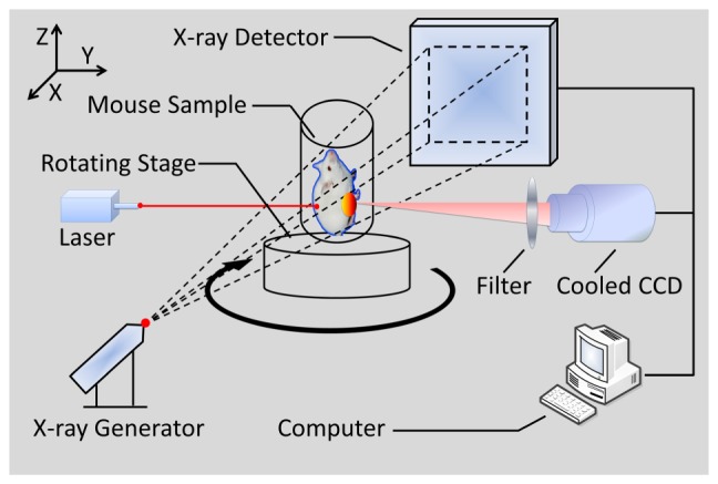
The schematic illustration of the hybrid optical/micro-CT imaging system. It provides multi-view FMT and micro-CT.
The main process of in vivo experiments can be summarized as following. Firstly, the mouse was injected through the caudal tail vein with 0.4 ml Fenestra vascular contrast agent to enhance the micro-CT images, followed by 0.3 ml of anesthetic at a 0.15g/ml concentration via intraperitoneal injection. When the anesthetic set in, a bead filled with cy5.5 solution with a concentration of 2000nM was embedded stereotactically into the body of the mouse in the vicinity of its liver. This fluorescent solution had an extinction coefficient of 0.019 and a quantum efficiency of 0.23 at the peak excitation wavelength of 671nm [33]. It is worth to mention that the reconstruction accuracy of the proposed method can be examined in this study, since the luminescent bead was wrapped in a plastic material, which could be easily detected by the micro-CT system. About half an hour after the injection of the Fenestra vascular contrast agent, the mouse was placed on the automatic rotation stage, as delineated in Fig. 8. Secondly, we began to collect the dual-modality raw data respectively. The acquisition time for the entire procedure was within 10min. The fluorescent signals emitted from the surface of the mouse body were captured in several different views by the cooled CCD camera. And then the cone-beam micro-CT projection data with 360° views was scanned using the x-ray generator and detector.
After collecting the raw data, some essential preprocessing operations were carried out and set the data set suitable for posterior FMT reconstruction.
(1). Micro-CT Reconstruction: The cone-beam micro-CT projection data were reconstructed by the Feldkamp-Davis-Kress (FDK) algorithm on commodity GPU using an acceleration scheme [34] to yield the 3D volume data, three slices of which are shown in Fig. 9 where the yellow squares mark the location of the fluorescent bead at the coordinate (34.40, 33.80, 6.40)
(2). Segmentation: In order to build the heterogeneous mouse model delineated in Fig. 10 , we performed segmentation on six main kinds of organs including muscle, lungs, heart, liver, bone, and kidneys through a combination method of interactive and threshold segmentation. The optical properties for different organs were calculated according to the literature [35] and are listed in Table 5
(3). Discretization: Prior to solving the FMT inverse problem using the finite element method, we performed meshing on the segmented micro-CT data of the mouse body. Here, the torso section of the mouse was discretized into a volumetric mesh containing 4,659 nodes and 22,667 tetrahedral elements
(4). Registration: In order to portray the photon distribution on the surface of the mouse body, the optical fluorescent images were mapped onto the surface of the volumetric mesh in terms of space and energy. The surface energy mapping was carried out by using a 3D surface flux reconstruction algorithm [36], as is seen in Fig. 10(c)
Fig. 9.
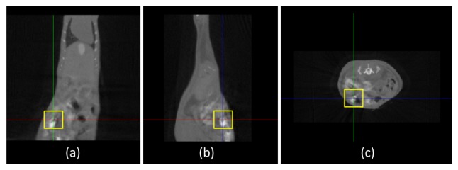
Three slices of the micro-CT mouse data, where the yellow square marks the location of the luminescent bead; (a) the coronal view; (b) the sagittal view; (c) the transversal view.
Fig. 10.
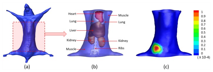
The heterogeneous mouse model for the in vivo experiment. (a) The heterogeneous mouse body. (b) The heterogeneous mouse torso used for imaging reconstructions, including heart, lungs, liver, muscle, kidneys, and bone. (c) The surface view of the mouse torso with the front view measurement distribution mapped on it.
Table 5. Optical properties of the mouse model.
| Material | Muscle (mm−1) | Lungs (mm−1) | Heart (mm−1) | Liver (mm−1) | Kidneys (mm−1) | Bone (mm−1) |
|---|---|---|---|---|---|---|
| 0.0849 | 0.1918 | 0.0574 | 0.3437 | 0.0644 | 0.0593 | |
| 0.4273 | 2.1720 | 0.9620 | 0.6770 | 2.2480 | 2.4900 | |
| 0.0563 | 0.1266 | 0.383 | 0.2283 | 0.0430 | 0.0393 | |
| 0.3792 | 2.1240 | 0.9050 | 0.6480 | 2.1090 | 2.3400 |
After the above procedures, we used the finite element method to solve the FMT inverse problem and used three different reconstruction methods (the IS_L1 method, the StOMP method, and the proposed method) to perform the FMT reconstruction. The 3D results reconstructed by the IS_L1 method, the StOMP method and the proposed method are shown in Fig. 11 . The muscle region is set to be translucent, so that the reconstructed sources is not covered. Quantitative comparisons of the reconstruction results for the above three methods are shown in Fig. 12 and Table 6 . It can be perceived that there were more than one reconstructed sources inside the torso of mouse reconstructed by the StOMP method, and the smaller reconstructed sources were far away from the center of the real source, although the reconstructed location center was (34.05, 33.50, 6.07) and had a location error of only 0.57mm. The reconstructed center position of the fluorescent source was (34.11, 35.33.6.44) for the IS_L1 method, and (34.05, 33.50, 6.07) for the proposed method. The corresponding location errors were 0.57 mm and 1.56 mm respectively. Although both of the reconstructed fluorescent sources had a small distance from the actual source in center position, artifacts appeared near the reconstructed fluorescent source in the results of the IS_L1 method, whereas artifacts did not appear in the proposed method’s results. The reconstructed location error by the proposed method was acceptable, because the errors may have been caused by the diffusion equation model, the geometrical approximation, the optical properties’ inaccuracy, the surface energy mapping, and so on. The reconstruction time for the proposed method was 5.5625s and was much faster than the two contrasting methods, which demonstrated the absolute advantages of the proposed method in efficiency.
Fig. 11.
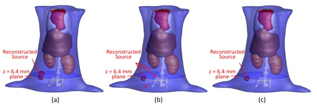
The iso-surface 3D views of the reconstruction results using the IS_L1 method, the StOMP method and the proposed method. (a) The reconstruction results by the IS_L1 method. (b) The reconstruction results by the StOMP method. (c) The reconstruction results by the proposed method.
Fig. 12.
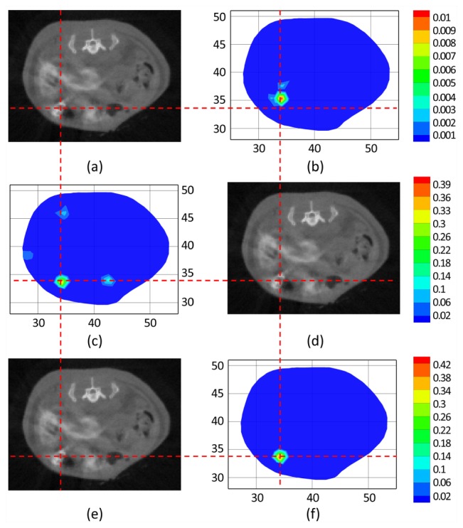
The comparisons of the reconstruction results for in vivo mouse experiments. The cross-sections of the reconstruction results by different methods are compared to the corresponding micro-CT slices. The crosshairs of the red dashed lines denote the actual source center. (b), (c) and (f) are the lateral cross-sectional views of the reconstruction results at the z = 6.4 mm plane by the IS_L1 method (b), the StOMP method (d) and the proposed method (f) respectively. (a), (d) and (e) are the corresponding micro-CT slices respectively.
Table 6. Comparisons of the reconstruction results between different methods. Location Error denotes the distance between the center of the real source and the center of the reconstructed one.
| Method | Actual Location Center (mm) |
Reconstructed Location Center (mm) | Location Error (mm) |
Reconstruction Time (s) |
|---|---|---|---|---|
| IS_L1 | (34.40, 33.80, 6.40) | (34.11, 35.33.6.44) | 1.56 | 141.4531 |
| StOMP | (34.40, 33.80, 6.40) | (34.05, 33.50, 6.07) | 0.57 | 8.7188 |
| Proposed | (34.40, 33.80, 6.40) | (34.05, 33.50, 6.07) | 0.57 | 5.5625 |
The above findings suggested that the proposed method was able to reconstruct the fluorescent source accurately and had the potential to detect the lesions in practical biomedical applications.
5. Discussion and conclusion
In this paper, a novel sparsity adaptive subspace pursuit method is proposed and analyzed for FMT reconstruction. This reconstruction method is proven to be accurate, robust and high-efficient for fluorescent source reconstruction mainly through using the following three strategies:
-
(1)
A subspace projection and correlation maximization approach has been utilized to simplify the FMT problem and treat the FMT problem with sparsity-promoting L1-norm regularization as the basis pursuit problem. Based on this, a new sparse reconstruction problem, with a greatly reduced order compared to the original optimization problem is formed between the measurement data sets and the permissible coefficients.
-
(2)
Instead of using traditional methods, which require the sparsity factor as a priori for exact reconstruction, a sparsity adaptive strategy has been proposed to estimate the sparsity of the FMT problem. This innovative feature makes the proposed method a promising candidate for many practical FMT applications when the number of non-zero coefficients of the fluorescent source distribution is not available.
-
(3)
A backtracking technique has been proposed to re-evaluate the reliability of all candidates at each iteration of the reconstruction process and to remove the wrong items added in the previous iteration, which can make the reconstruction method more robust and the reconstruction results more accurate.
Moreover, three numerical experiments based on a mouse-mimicking heterogeneous phantom and an in vivo experiment based on an adult Kunming mouse have been conducted to evaluate the feasibility of our method in fluorescent source reconstruction. The results demonstrate that:
-
(1)
The reconstruction accuracy of the proposed method has been validated by the experiment on different mouse-mimicking heterogeneous phantom setups for a single source, double sources, and triple sources, and the results indicate that it is able to localize different fluorescent sources with a position bias less than 1 mm.
-
(2)
The proposed reconstruction method has been proven to be more efficient compared to the classical approaches, and it becomes more computationally competitive as the data set grows larger.
-
(3)
The reconstruction robustness of the proposed method has been verified in that it can obtain satisfactory fluorescent source reconstruction results even under quite ill-posed conditions, for example, when the measurement data sets are quite limited.
-
(4)
The potential of the proposed method on the application of FMT has been further validated by an in vivo experiment on an adult Kunming mouse model, in which a small fluorescent source in the vicinity of the mouse’s liver has been accurately reconstructed.
For FMT problems, the diffuse approximation model has been extensively used to mimick photon propagation in biological tissues. The advantage of this model is computationally efficient and has an explicit physical meaning. However, more accurate models to describe photon propagation in biological tissues are also necessary for higher quality of 3D imaging reconstruction. In recent years, although the computational complexity of these models are high, several complex models such as the simplified spherical harmonics approximation (SPN) model have been proposed to improve the optical tomography reconstruction quality. Our method can also be utilized in these complex models with few modifications.
Future work will focus on in vivo experiments with probe-marked mouse models, which is quite important for tumor detection. In addition, the in vivo experiment will be extended further to detect weak optical signals from the internal fluorescent sources at different depths as well as multiple sources instead of only one. The FMT reconstruction for mouse models with multiple sources will be conducted in future studies.
Acknowledgments
This paper is supported by the National Basic Research Program of China (973 Program) under Grant No. 2011CB707700, the National Natural Science Foundation of China under Grant Nos. 81027002 and 81227901, and the Chinese Academy of Sciences Visiting Professorship for Senior International Scientists under Grant No. 2012T1G0036. The authors thank Adjunct Assistant Professor Dr. Karen M. von Deneen from the University of Florida and Dr. Yang Du for their modifications in this paper.
References and links
- 1.Fan-Minogue H., Cao Z., Paulmurugan R., Chan C. T., Massoud T. F., Felsher D. W., Gambhir S. S., “Noninvasive molecular imaging of c-Myc activation in living mice,” Proc. Natl. Acad. Sci. U.S.A. 107(36), 15892–15897 (2010). 10.1073/pnas.1007443107 [DOI] [PMC free article] [PubMed] [Google Scholar]
- 2.Whitney M. A., Crisp J. L., Nguyen L. T., Friedman B., Gross L. A., Steinbach P., Tsien R. Y., Nguyen Q. T., “Fluorescent peptides highlight peripheral nerves during surgery in mice,” Nat. Biotechnol. 29(4), 352–356 (2011). 10.1038/nbt.1764 [DOI] [PMC free article] [PubMed] [Google Scholar]
- 3.van Dam G. M., Themelis G., Crane L. M., Harlaar N. J., Pleijhuis R. G., Kelder W., Sarantopoulos A., de Jong J. S., Arts H. J., van der Zee A. G., Bart J., Low P. S., Ntziachristos V., “Intraoperative tumor-specific fluorescence imaging in ovarian cancer by folate receptor-α targeting: first in-human results,” Nat. Med. 17(10), 1315–1319 (2011). 10.1038/nm.2472 [DOI] [PubMed] [Google Scholar]
- 4.Ntziachristos V., “Fluorescence molecular imaging,” Annu. Rev. Biomed. Eng. 8(1), 1–33 (2006). 10.1146/annurev.bioeng.8.061505.095831 [DOI] [PubMed] [Google Scholar]
- 5.Ale A., Ermolayev V., Herzog E., Cohrs C., de Angelis M. H., Ntziachristos V., “FMT-XCT: in vivo animal studies with hybrid fluorescence molecular tomography-X-ray computed tomography,” Nat. Methods 9(6), 615–620 (2012). 10.1038/nmeth.2014 [DOI] [PubMed] [Google Scholar]
- 6.Ntziachristos V., “Going deeper than microscopy: the optical imaging frontier in biology,” Nat. Methods 7(8), 603–614 (2010). 10.1038/nmeth.1483 [DOI] [PubMed] [Google Scholar]
- 7.Song X. L., Wang D. F., Chen N. G., Bai J., Wang H., “Reconstruction for free-space fluorescence tomography using a novel hybrid adaptive finite element algorithm,” Opt. Express 15(26), 18300–18317 (2007). 10.1364/OE.15.018300 [DOI] [PubMed] [Google Scholar]
- 8.Wang D. F., Song X. L., Bai J., “Adaptive-mesh-based algorithm for fluorescence molecular tomography using an analytical solution,” Opt. Express 15(15), 9722–9730 (2007). 10.1364/OE.15.009722 [DOI] [PubMed] [Google Scholar]
- 9.Bangerth W., Joshi A., “Adaptive finite element methods for the solution of inverse problems in optical tomography,” Inverse Probl. 24(3), 034011 (2008). 10.1088/0266-5611/24/3/034011 [DOI] [Google Scholar]
- 10.Cao N., Nehorai A., Jacobs M., “Image reconstruction for diffuse optical tomography using sparsity regularization and expectation-maximization algorithm,” Opt. Express 15(21), 13695–13708 (2007). 10.1364/OE.15.013695 [DOI] [PubMed] [Google Scholar]
- 11.Lin Y., Gao H., Nalcioglu O., Gulsen G., “Fluorescence diffuse optical tomography with functional and anatomical a priori information: feasibility study,” Phys. Med. Biol. 52(18), 5569–5585 (2007). 10.1088/0031-9155/52/18/007 [DOI] [PubMed] [Google Scholar]
- 12.Donoho D. L., “Compressed sensing,” IEEE Trans. Inf. Theory 52(4), 1289–1306 (2006). 10.1109/TIT.2006.871582 [DOI] [Google Scholar]
- 13.Mohajerani P., Eftekhar A. A., Huang J. D., Adibi A., “Optimal sparse solution for fluorescent diffuse optical tomography: theory and phantom experimental results,” Appl. Opt. 46(10), 1679–1685 (2007). 10.1364/AO.46.001679 [DOI] [PubMed] [Google Scholar]
- 14.Han D., Tian J., Liu K., Feng J., Zhang B., Ma X., Qin C., “Sparsity-promoting tomographic fluorescence imaging with simplified spherical harmonics approximation,” IEEE Trans. Biomed. Eng. 57(10), 2564–2567 (2010). 10.1109/TBME.2010.2053538 [DOI] [PubMed] [Google Scholar]
- 15.Han D., Tian J., Zhu S. P., Feng J. C., Qin C. H., Zhang B., Yang X., “A fast reconstruction algorithm for fluorescence molecular tomography with sparsity regularization,” Opt. Express 18(8), 8630–8646 (2010). 10.1364/OE.18.008630 [DOI] [PubMed] [Google Scholar]
- 16.Elad M., Matalon B., Zibulevsky M., “Coordinate and subspace optimization methods for linear least squares with non-quadratic regularization,” Appl. Comput. Harmon. Anal. 23(3), 346–367 (2007). 10.1016/j.acha.2007.02.002 [DOI] [Google Scholar]
- 17.Han D., Yang X., Liu K., Qin C., Zhang B., Ma X., Tian J., “Efficient reconstruction method for L1 regularization in fluorescence molecular tomography,” Appl. Opt. 49(36), 6930–6937 (2010). 10.1364/AO.49.006930 [DOI] [PubMed] [Google Scholar]
- 18.Blow N., “ In vivo molecular imaging: the inside job,” Nat. Methods 6(6), 465–469 (2009). 10.1038/nmeth0609-465 [DOI] [Google Scholar]
- 19.Bruckstein A. M., Donoho D. L., Elad M., “From sparse solutions of systems of equations to sparse modeling of signals and images,” SIAM Rev. 51(1), 34–81 (2009). 10.1137/060657704 [DOI] [Google Scholar]
- 20.Klose A. D., Ntziachristos V., Hielscher A. H., “The inverse source problem based on the radiative transfer equation in optical molecular imaging,” J. Comput. Phys. 202(1), 323–345 (2005). 10.1016/j.jcp.2004.07.008 [DOI] [Google Scholar]
- 21.Klose A. D., Larsen E. W., “Light transport in biological tissue based on the simplified spherical harmonics equations,” J. Comput. Phys. 220(1), 441–470 (2006). 10.1016/j.jcp.2006.07.007 [DOI] [Google Scholar]
- 22.Tan Y. Y., Jiang H. B., “DOT guided fluorescence molecular tomography of arbitrarily shaped objects,” Med. Phys. 35(12), 5703–5707 (2008). 10.1118/1.3020594 [DOI] [PubMed] [Google Scholar]
- 23.Joshi A., Bangerth W., Sevick-Muraca E. M., “Adaptive finite element based tomography for fluorescence optical imaging in tissue,” Opt. Express 12(22), 5402–5417 (2004). 10.1364/OPEX.12.005402 [DOI] [PubMed] [Google Scholar]
- 24.Lee J. H., Joshi A., Sevick-Muraca E. M., “Fully adaptive finite element based tomography using tetrahedral dual-meshing for fluorescence enhanced optical imaging in tissue,” Opt. Express 15(11), 6955–6975 (2007). 10.1364/OE.15.006955 [DOI] [PubMed] [Google Scholar]
- 25.Schweiger M., Arridge S. R., Hiraoka M., Delpy D. T., “The Finite Element Method for the Propagation of Light in Scattering Media: Boundary and Source Conditions,” Med. Phys. 22(11), 1779–1792 (1995). 10.1118/1.597634 [DOI] [PubMed] [Google Scholar]
- 26.Wang D. F., Liu X., Chen Y. P., Bai J., “A Novel Finite-Element-Based Algorithm for Fluorescence Molecular Tomography of Heterogeneous Media,” IEEE Trans. Inf. Technol. Biomed. 13(5), 766–773 (2009). 10.1109/TITB.2009.2015144 [DOI] [PubMed] [Google Scholar]
- 27.Cong A. X., Wang G., “A finite-element-based reconstruction method for 3D fluorescence tomography,” Opt. Express 13(24), 9847–9857 (2005). 10.1364/OPEX.13.009847 [DOI] [PubMed] [Google Scholar]
- 28.Milstein A. B., Stott J. J., Oh S., Boas D. A., Millane R. P., Bouman C. A., Webb K. J., “Fluorescence optical diffusion tomography using multiple-frequency data,” J. Opt. Soc. Am. A 21(6), 1035–1049 (2004). 10.1364/JOSAA.21.001035 [DOI] [PubMed] [Google Scholar]
- 29.Cong W. X., Wang G., Kumar D., Liu Y., Jiang M., Wang L. V., Hoffman E. A., McLennan G., McCray P. B., Zabner J., Cong A., “Practical reconstruction method for bioluminescence tomography,” Opt. Express 13(18), 6756–6771 (2005). 10.1364/OPEX.13.006756 [DOI] [PubMed] [Google Scholar]
- 30.Qin C. H., Zhu S. P., Tian J., “New Optical Molecular Imaging Systems,” Curr. Pharm. Biotechnol. 11(6), 620–627 (2010). 10.2174/138920110792246519 [DOI] [PubMed] [Google Scholar]
- 31.Zhu S., Tian J., Yan G., Qin C., Feng J., “Cone beam micro-CT system for small animal imaging and performance evaluation,” Int. J. Biomed. Imaging 2009, 960573 (2009). 10.1155/2009/960573 [DOI] [PMC free article] [PubMed] [Google Scholar]
- 32.Wu P., Liu K., Zhang Q., Xue Z., Li Y., Ning N., Yang X., Li X., Tian J., “Detection of mouse liver cancer via a parallel iterative shrinkage method in hybrid optical/microcomputed tomography imaging,” J. Biomed. Opt. 17(12), 126012 (2012). 10.1117/1.JBO.17.12.126012 [DOI] [PubMed] [Google Scholar]
- 33.Gao F., Zhao H., Tanikawa Y., Yamada Y., “A linear, featured-data scheme for image reconstruction in time-domain fluorescence molecular tomography,” Opt. Express 14(16), 7109–7124 (2006). 10.1364/OE.14.007109 [DOI] [PubMed] [Google Scholar]
- 34.Yan G., Tian J., Zhu S., Dai Y., Qin C., “Fast cone-beam CT image reconstruction using GPU hardware,” J. XRay Sci. Technol. 16, 225–234 (2008). [Google Scholar]
- 35.Alexandrakis G., Rannou F. R., Chatziioannou A. F., “Tomographic bioluminescence imaging by use of a combined optical-PET (OPET) system: a computer simulation feasibility study,” Phys. Med. Biol. 50(17), 4225–4241 (2005). 10.1088/0031-9155/50/17/021 [DOI] [PMC free article] [PubMed] [Google Scholar]
- 36.Chen X., Gao X., Chen D., Ma X., Zhao X., Shen M., Li X., Qu X., Liang J., Ripoll J., Tian J., “3D reconstruction of light flux distribution on arbitrary surfaces from 2D multi-photographic images,” Opt. Express 18(19), 19876–19893 (2010). 10.1364/OE.18.019876 [DOI] [PubMed] [Google Scholar]


