Abstract
Wireless power, when coupled with miniaturized implantable electronics, has the potential to provide a solution to several challenges facing neuroscientists during basic and preclinical studies with freely behaving animals. The EnerCage system is one such solution as it allows for uninterrupted electrophysiology experiments over extended periods of time and vast experimental arenas, while eliminating the need for bulky battery payloads or tethering. It has a scalable array of overlapping planar spiral coils (PSCs) and three-axis magnetic sensors for focused wireless power transmission to devices on freely moving subjects. In this paper, we present the first fully functional EnerCage system, in which the number of PSC drivers and magnetic sensors was reduced to one-third of the number used in our previous design via multicoil coupling. The power transfer efficiency (PTE) has been improved to 5.6% at a 120 mm coupling distance and a 48.5 mm lateral misalignment (worst case) between the transmitter (Tx) array and receiver (Rx) coils. The new EnerCage system is equipped with an Ethernet backbone, further supporting its modular/scalable architecture, which, in turn, allows experimental arenas with arbitrary shapes and dimensions. A set of experiments on a freely behaving rat were conducted by continuously delivering 20 mW to the electronics in the animal headstage for more than one hour in a powered 3538 cm2 experimental area.
Keywords: Biotelemetry, behavioral neuroscience, environmental enrichment, planar spiral coils (PSCs), wireless power transmission
I. Introduction
EXPERIMENTS in behavioral neuroscience typically employ small animal subjects, such as fish or rodents, to help improve our understanding of the nervous system and its pathology [1]. In particular, data from basic and preclinical in vivo electrophysiology experiments have helped develop treatments for disorders ranging from schizophrenia to Parkinson's, epilepsy, and depression [2]. These experiments on awake, behaving animals typically use cables to transfer power to and neural data from instruments attached to the animal body, thereby restricting the recording arena to relatively small sizes and prohibiting the use of enriched environments, such as tunnels or burrows [3]. Environmental enrichment has received strong support as a means of improving the quality of the data generated by these experiments [4], and there is a large body of research indicating that it leads to increased learning and brain plasticity [5]–[11]. In addition, the cables prohibit experiments involving recording from more than one animal at a time in a single enclosure.
In an attempt to circumvent these problems, several battery-powered neural recording systems have been developed [13]–[17]. However, these setups are not suitable for longitudinal studies due to the limited lifetime of the batteries and necessary handling of the animal subjects for replacing or recharging the batteries. The batteries also add considerable weight to the animal payload, potentially biasing the subjects' behavior by creating an impoverished environment.
Several wirelessly powered systems have been developed to address these limitations and to meet the increasing use of higher powered applications such as optogenetics [18]. These systems can be divided into those that operate in the far field within the ultra-high frequency (UHF) band, and deliver power via antennas, and those that operate in the near field within the HF band, and deliver power via inductively coupled coils [19]. Current UHF systems are only suitable for ultra low power applications, such as neural recording from a small number of sites, because they tend to provide power transfer efficiencies (PTEs) below 1%. Any attempt to increase the power delivered to the load (PDL) may result in surpassing the safe specific absorption rate (SAR) limits for the research staff working near the cage and/or the animal subject [20]–[24]. The focus of this paper is on inductively powered HF systems, some of which have already received regulatory approval and become commercially available [25], [26]. The current systems, however, tend to energize the entire cage and suffer from inhomogeneity of the magnetic field across the experimental area and heat dissipation. As a result, they can only support experiments that can be conducted in a small space, about the size of a rodent home cage.
In order to extend the size of the wirelessly powered area, the use of coil arrays has been proposed for long-term animal experiments as well as wireless charging of small consumer electronics, such as smartphones and laptops [27]–[32]. Nonetheless, a complete system with architectural details and functional characterization has not been demonstrated.
We reported on the design and preliminary development of a smart experimental arena, called the EnerCage system, for long-term electrophysiology experiments in [33]. This HF system was designed to deliver up to 20 mW at 13.56 MHz in the industrial-scientific-medical (ISM) band to devices at coupling distances, d, up to 120 mm. The EnerCage system is fully compatible with our inductively powered multichannel wireless implantable neural recording (WINeR) system and any other data acquisition, stimulation, or drug delivery system that can operate under these conditions [34]. It offers a few advantages over previous wirelessly powered electrophysiology setups: 1) it is capable of conforming to experimental arenas with arbitrary shapes and dimensions; 2) it creates a focused and yet homogeneous magnetic field distribution across these arbitrary shaped arenas; 3) it significantly reduces the risk of exposure to excessive electromagnetic field; and 4) low power consumption and thus heat dissipation (Maximum power: 4 W for one active hex-PSC plus 0.11 W/passive hex-PSC). These features have become possible by utilizing: 1) a modular and scalable system architecture; 2) a geometrically optimized array of overlapping hexagonal planar spiral coils (hex-PSCs); 3) dynamic closed-loop control of the wirelessly received power; 4) a dual-band bidirectional wireless data link; and 5) wireless non-line-of-sight tracking of the animal subjects via an array of magnetic sensors, which allow activation of only one hex-PSC at a time [33]–[37].
In this paper we report, for the first time, on a fully functional EnerCage system prototype, and discuss its system architecture and key features in the following section. More details on the inductive link and the magnetic localization are included in Sections III and IV, respectively. In vivo measurement results are presented in Section V, followed by concluding remarks.
II. Enercage System Architecture
In the preliminary design of the EnerCage system, each control module communicated with three sensors and drove three overlapping hex-PSCs with three power amplifiers (PAs). The control module also included a local microcontroller (MCU) that communicated with the central PC station via a central MCU [33]. While providing satisfactory performance, that design was complex and inefficient in terms of cost. Moreover, the limited number of ports on the central MCU limited the number of modules that could be added. By taking advantage of multicoil power transmission and Ethernet, the new EnerCage system architecture reduces the system cost and complexity by more than 65%, while providing higher PTE and lifting the limits on system scalability [38].
A. Stationary Unit
Fig. 1 shows a rendering of the new EnerCage system. A mobile unit (headstage, backpack, or implant), which is embedded with two receiver (Rx) coils and a magnetic tracer, is carried by a freely behaving small animal subject. A stationary unit, consisting of rectangular printed circuit board (PCB) modules, forms a three-layer array of overlapping hex-PSCs with optimized geometries that tile the floor of the experimental arena [35]. The hex-PSC closest to the animal, which is often in the best position to power the mobile unit, is activated by a class-C PA that drives a hex-PSC on the third layer from the top (red). If the closest hex-PSC is on the third layer, it will directly couple onto the mobile unit by forming a three-coil link. If the closest hex-PSC is on the first (blue) or second (green) layer, a four-coil link will be formed with one of the overlapping red PSCs [38], [39]. This mechanism is described in section III in more detail. Hence, the three PAs in each control module, vertically mounted with SMA connectors under the hex-PSC array, can activate the area covered by nine overlapping hex-PSCs. An array of three-axis magnetic sensors (AMI360, Aichi Steel, Japan), which has been evenly distributed under the hex-PSC array (red circles in Fig. 1), locates the magnetic tracer in the mobile unit based on the algorithm described in section IV.
Fig. 1.
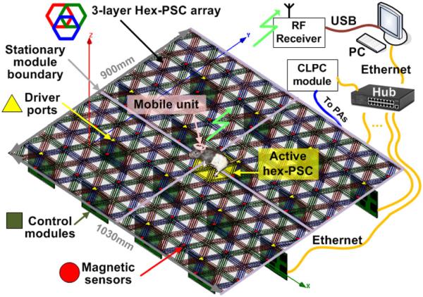
Rendered view of the EnerCage system showing its modular architecture. An array of three-axial magnetic sensors track the animal in real time to focus the 13.56 MHz magnetic field around the animal body by activating a printed spiral coil that is in the best position to power the mobile unit on the animal body. All control modules are connected via Ethernet to a hub and a central PC station. The mobile unit receives wireless power, transmits the acquired data, and controls stimulation or drug delivery.
Each control module is managed by an MCU (MSP430), as shown in Fig. 2. However, instead of communicating with another MCU, it has been equipped with an Ethernet port (XPort, Lantronix, Irvine, CA) with a unique internet protocol (IP) address to communicate with the central PC station via an Ethernet hub. Using a 48-port Ethernet switch, 432 overlapping hex-PSCs can be controlled from a central PC, which can cover a small room. The MCU is also responsible for delivering control signals from the PC to three HF radio frequency identification (RFID) readers (TRF7960) and collecting data from magnetic sensors. Each RFID reader controls a class-C PA, which drives its associated hex-PSC at >68% efficiency. The carrier frequency, fc = 13.56 MHz, is in the ISM band and the hex-PSC geometries have been optimized accordingly [35]. Based on the magnetic tracking data, the central PC determines which hex-PSC to activate using the algorithm described in Section IV. It also receives information that indicates the amount of power received by the mobile unit either via the load-shift-keying (LSK) feature of the RFID link or via a 2.4-GHz RF link directly from the mobile unit MCU, to adjust the transmitted power in a closed-loop fashion [36]. The closed-loop power control (CLPC) module, which has its own XPort and IP address, is also connected to the Ethernet hub and dynamically adjusts the PA supply voltage (Tx_VD D) to maintain the desired received power across the Rx coils.
Fig. 2.
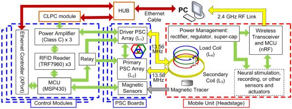
Block diagram of the sensing, control, and interfacing electronics in the EnerCage system.
B. Mobile Unit
Fig. 3 shows the schematic diagram of the prototype mobile unit, which is powered through a three/four-coil link to demonstrate the closed-loop-controlled wireless power transfer capability of the EnerCage system. The mobile unit consists of two Rx coils, L3 and L4, for load impedance matching, a rectifier, a 3 V regulator (Vreg), an LSK switch (M2), an LED indicator, and a system-on-a-chip (SoC) MCU (nRF24LE1, Nordic Semiconductor, Norway), which includes a built-in 10-bit analog-to-digital converter (ADC) and a 2.4 GHz transceiver.
Fig. 3.

Schematic diagram of the RFID-based hex-PSC drivers with closed-loop power control via back telemetry from the mobile unit [36]–[39].
The 13.56 MHz carrier is full-wave rectified, divided by two (0.5 × Vrec), and digitized with respect to a Vreg = 3 V reference voltage at 30 Hz. The resulting 10-bit Vrec samples are sent wirelessly to the PC for monitoring purposes. The MCU also uses M1 to blink the LED for optical tracking of the animal subject and proof of mobile unit functionality. When the Rx coils tilt >60° relative to the surface of the stationary unit, or when the animal subject stands on its rear legs (d > 120 mm), the received power is interrupted even with the maxed-out PA output. During these occasions, a Cs = 0.47 F super capacitor in the mobile unit supplies the headstage for up to 30 s.
To close the power control loop, Vrec/2 samples are compared with a threshold value in the MCU. If Vrec > 4 V, the LSK periodically shorts the L4C4-tank by closing M2 at a rate of 700 Hz. These short pulses (20 μs) indicate that the received power is more than sufficient, and that the Tx output power should be reduced by decreasing Tx_VD D. On the other hand, if Vrec < 4 V, the lack of LSK pulses results in the Tx_VD D to be incrementally increased by the CLPC at an adjustable rate. This mechanism maintains Vrec at 4 V [36]. The power loop can also be closed using the Vrec data, received wirelessly at the PC. In this option, Vrec is subtracted from a designated voltage in the PC, and the error value controls Tx_VD D of the CLPC module.
III. Multicoil Inductive Power Transfer
Hex-PSCs on the stationary unit are divided into driver PSCs, which are directly driven by the PAs and labeled L1 in Figs. 2 and 3, and primary PSCs, labeled L2. Three driver hex-PSCs, shown in red in Fig. 4, are driven by three PAs on each vertical control module. Each driver PSC is associated with two of the six primary hex-PSCs that it overlaps, which are shown in green and blue in Fig. 4. This design reduces the number of drivers and control modules to one-third of the number used in our earlier EnerCage system architecture in [33], while maintaining high PTE by using the multicoil coupling scheme [38].
Fig. 4.
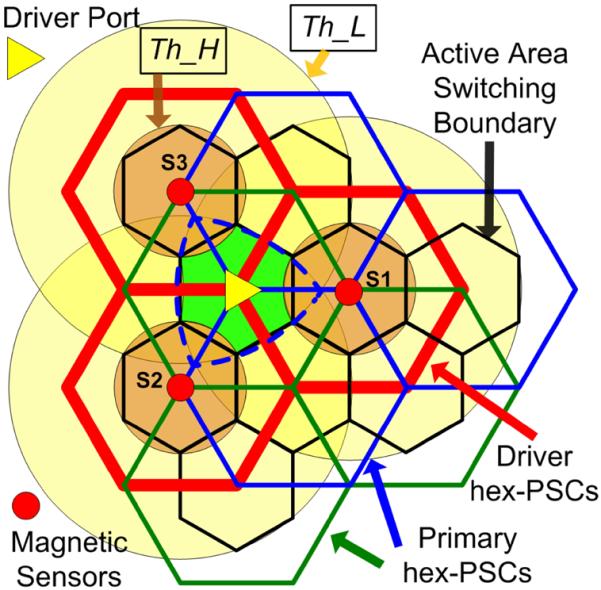
Every nine overlapping hex-PSCs in the EnerCage system are controlled by one vertical control module in Fig. 1. Each magnetic sensor output vector is compared with two different thresholds, Th_H and Th_L, to track the position of the animal subject and determine the active hex-PSC.
A. Multicoil Coupling
In the new EnerCage system, the location of the mobile unit (animal subject) determines whether the three- or four-coil coupling is utilized, as shown in Fig. 5. For example, if the subject is located above a driver hex-PSC (A), the coupling mechanism would be three-coil (L1 to L3–L4), but if it is located above a primary hex-PSC (B or C), the associated driver hex-PSC delivers power through that primary hex-PSC via the four-coil mechanism (L1–L2 to L3–L4) [38]. Therefore, each control module is associated with three driver and six primary hex-PSCs.
Fig. 5.
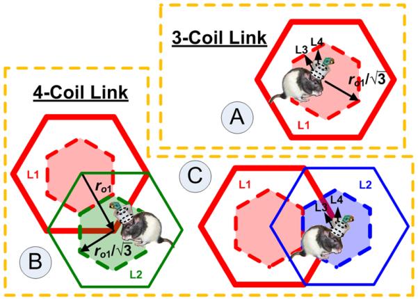
Multicoil coupling conditions in EnerCage: (A) three-coil power transfer link and (B and C) four-coil power transfer link. Considering the active area for each hex-PSC (dashed lines), the maximum lateral misalignment of the Rx is .
Multicoil links have been extensively studied in the literature and shown to provide higher PTEs [38]–[41]. The PTE of a three-coil link can be found from [38]
where k13 is the coupling coefficient between the driver hex-PSC and L3 in the mobile unit and k34 is the coupling coefficient between the two coils in the mobile unit (see Fig. 3), which can be found from Maxwell's equation [42], [43]. Qi = ωLi/Ri is the quality factor of the ith hex-PSC. It should be noted that for the load hex-PSC, L4, which is connected in series with RL, Q4L = ωL4/(R4 + RL). Similarly, for the driver hex-PSC, L1, which is connected in series to the source, Rs should be added to R1.
The PTE in four-coil links can be found from [38], as shown (2), at the bottom of this page, where k12 is the coupling between the driver and primary hex-PSCs. The value of k12 depends primarily on the lateral misalignment between hex-PSCs, defined by the radius of the primary hex-PSCs, ro1 in Fig. 5, as well as the thickness of the PCB, which defines the distance between the hex-PSCs in different PCB layers. k13, k14, and k24 couplings are neglected in comparison with k23 because of the considerable distance and misalignments between Rx coils and these hex-PSCs. The worst PTE is expected from the primary hex-PSCs on the second metal layer (green) from top because they are affected by the parasitics from both top layer (blue) and third layer (red). The design of the inductive link should therefore be based on four-coil coupling involving the second metal layer in order to account for the worst-case conditions [35].
B. Hex-PSC Optimization
On the Tx side (stationary unit), the hex-PSC array has been implemented by three overlapping metal layers in a stack of two double-layer PCBs with 1.7 mm spacing made of FR4 substrate with 2-oz copper. This means the FR4 dielectric thickness ts = 1.6 mm and the copper thickness t0 = 70 μm. Therefore, the dielectric material under layers 1 and 3 from the top is FR4, while the one under layers 2 and 4 is air. Layer 4 is used for the hex-PSC tuning and matching capacitors, an array of relays to open circuit the inactive primary hex-PSCs in order not to couple onto the active hex-PSC, and their interconnects.
On the Rx side (mobile unit), a wire-wound coil is used for L3 to boost Q3 and a multilayer PCB coil is used for L4, as shown in Fig. 2, to limit the weight of the mobile unit. The maximum allowable diameter for L3 was 40 mm, based on the size of a headstage designed for a multichannel neural recording system [17]. Therefore, the inductive link was optimized for the worst-case coupling at a lateral misalignment between the Tx and Rx coils, which occurs at , as shown in Fig. 5 [35].
To a large extent, the optimal Tx and Rx coil geometries depend on the average size of the animal subject species. In the current EnerCage design, the coils were optimized for large Long-Evans rats (400–600 g) [44], with a maximum coupling distance of d = 120 mm, fc = 13.56 MHz, and nominal loading of RL = 500 Ω. Considering these initial design constraints, the iterative optimization procedure in [35], [38], and [42] was used to maximize the PTE. The goal was to minimize the coupling variations as the subject moved across the hex-PSC array. It should be noted that in order to avoid further complexity, angular misalignments were not considered here. Following optimization, a field solver, HFSS (ANSYS, Pittsburgh, PA), was used to verify and fine tune the values suggested by the theoretical models [35], [38], [42].
Table I summarizes the geometries of the optimized coils. The measured PTE was lower than the calculated and simulated values due to the fact that the model ignores some parasitic effects, such as those introduced by the interconnects on the 4th layer and the eddy currents induced in the hex-PSC array [35].
TABLE I.
EnerCage Coil Specifications Optimized at 13.56 MHz
| Parameter | Design Value | |
|---|---|---|
| Driver (L1) and primary (L2) hex-PSCs implemented on two double-layer FR4 PCBs in the stationary unit | Inductance = 0.68 μH | |
| Outer diameter = 16.6 cm | ||
| Number of turns = 2 | ||
| Line width = 8.66 mm | ||
| Line spacing = 2.60 mm | ||
| Q1 = 163 for driver PSC on layer 1 | ||
| Q2 = 127 for primary PSC on layer 2 | ||
| Q2 = 155 for primary PSC on layer 3 | ||
| Copper weight = 3.3 g | ||
|
| ||
| Wire-wound secondary coil (L3) in the mobile unit | Inductance = 1.25 μH | |
| Coil diameter = 40 mm | ||
| Wire diameter = 0.64 mm (22 AWG) | ||
| Number of turns = 4 | ||
| Q3 = 196 | ||
| Copper weight = 1.4 g | ||
|
| ||
| Multi-layer PCB load coil (L4) in the mobile unit | Inductance = 0.37 μH | |
| Coil diameter = 25 mm | ||
| Line width = 1 mm | ||
| Number of turns = 3 | ||
| Q4 = 177 | ||
| Copper weight = 0.3 g | ||
|
| ||
| L2 and L3 maximum relative distance (d23) | 120 mm (k23 = 0.035) | |
|
| ||
| L3 and L4 relative distance (d34) | 18 mm(k34 = 0.28) | |
|
| ||
| Overall efficiency (%) at d23 = 120 mm Max/Ave/Min* | 12.2/8.3/6.2 (3-coil) | 12.6/7.9/5.6 (4-coil) |
|
| ||
| Nominal loading (RL) (Ω) | 500 | |
Maximum misalignment in the worst-case PTE: γmax = 48.5 mm.
C. Stationary Hex-PSC Array Design
Considering the constraints imposed by the commercial PCB manufacturing process and the optimal hex-PSC geometries in Table I, the size of each hex-PSC unit tile was set to 515 × 450 mm2 as indicated by the solid lines in Fig. 6. Each unit tile includes 23 complete hex-PSCs (8 in layer 1, 8 in layer 2, and 7 in layer 3), and 30 incomplete hex-PSCs. Each tile can support 4 controller modules, which can activate 12 driver hex-PSCs. Each control module, vertically mounted at the yellow triangles in Figs. 1 and 4, houses the digital control circuitry and three PAs that drive the L1 hex-PSCs, as shown in Fig. 2. Fig. 4 shows how the EnerCage modular architecture can be scaled to support any arbitrarily sized experimental arena. Each tile is also equipped with twelve three-axis magnetic sensors, represented by the red dots in Figs. 1 and 6.
Fig. 6.
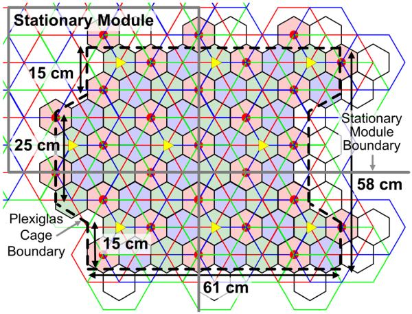
EnerCage unit tile (515 × 450 mm2) for the stationary unit and the boundaries of the 3538 cm2 experimental arena constructed by Plexiglas walls over four identical stationary modules.
IV. Non-Line-of-Sight Magnetic Tracking
A. Switching Algorithm
The EnerCage system minimizes power usage by turning on the closest hex-PSC to the animal subject. As the subject moves from one hex-PSC to the next, the ideal switching point is halfway between the two hex-PSCs. Since each hex-PSC has six neighbors, the switching points form hexagons, which are drawn with dashed lines in Fig. 5. These hexagons indicate the active area of each hex-PSC, within which the control software, running on the central PC, should activate that hex-PSC.
Magnetic sensors are evenly distributed under the stationary unit at the center of each driver hex-PSC and sampled at 500 Hz by the MCU. Every 17 samples were averaged into one sample to reduce the sensor noise and interference, mainly from the RF carrier, and sent to the PC station at 29.4 Hz via Ethernet. During the initialization phase, when there is no mobile unit, (containing the magnetic tracer) in the experimental arena, the data acquisition software measures the magnetic field from every sensor and stores those values, which represent the earth's magnetic field (EMF) at the location where the EnerCage has been installed, to be subtracted from every subsequent measurement by those sensors. As a result, the sensors' output variations were mainly caused by the changes in the location and orientation of the magnetic tracer.
Following EMF cancelation, the x–y–z axes from each sensor are added to generate the magnetic field vector at the location of that sensor. If the amplitude of the magnetic field vector surpasses an experimentally determined threshold Th_H, the tracer is considered to be within the small orange circle in Fig. 4 that encompasses the active area around that sensor. This will result in activation of the collocated driver hex-PSC. A second, lower threshold Th_L is represented by the large yellow circles around each sensor, and if three adjacent sensors have values greater than Th_L, the tracer is considered to be within the dashed blue Reuleaux triangle at the center of Fig. 4. The control software always gives priority to values above Th_H. Therefore, if no sensor is >Th_H, but three adjacent sensors are >Th_L, the tracer is located within the green hexagonal area in between those sensors in Fig. 4, and the control software activates the underlying primary hex-PSC.
Since the magnitude of the magnetic field vector remains almost constant when the magnetic tracer maintains its distance from a sensor, a constant vector magnitude represents a virtual dome around that sensor. Therefore, the switching locations around each sensor vary with the height of the magnetic tracer. In the current EnerCage prototype, Th_H and Th_L thresholds are determined based on the sensor outputs generated when the tracer was positioned at a height of 120 mm [37].
Above 120 mm, all circles in Fig. 4 become smaller and the dashed blue triangle extends into the driver hex-PSC domains. Thus, the primary hex-PSC domains expand at the expense of the driver hex-PSC domains. In addition, at the boundary between the blue and green domains, a new region begins to form that does not belong to either one of the primary hex-PSC domains. When the tracer moves into those regions, the system is programmed to continue driving the last active hex-PSC.
Below 120 mm, the driver hex-PSC domains expand and the primary hex-PSC domains shrink. This may cause the system to occasionally activate the wrong hex-PSC. Since the domain expansion is less than the diameter of each domain, in the worst case an adjacent hex-PSC is activated and the mobile unit still receives some power. Moreover, the PSC activation algorithm applies a hysteresis window, which alleviates flickering due to noise and interference at the cost of reduced PSC switching point accuracy [33]. In the future, we plan to use multiple three-axis sensor data that are proximal to the tracer in an accurate three-dimensional (3-D) magnetic localization algorithm by solving the inverse problem instead of the current threshold-based method [45].
B. Graphical User Interface
The EnerCage system is designed to be modular and conform to arbitrarily sized experimental arenas. Since the primary PSC activation is decided based on the values of three adjacent magnetic sensors, the graphical user interface (GUI), running on the PC should be aware of the physical and relative positions of all sensors to know which sensor output values to process and which hex-PSC to activate. Each vertical control module, shown in Fig. 2, has an IP address that it uses for TCP/IP communication with the central PC. To associate the sensors' data with their positions in physical space, the user initially enters the desired number of rows and columns of control modules and their IP addresses. The GUI draws matrix of three clustered overlapping red, blue, and green circles on the PC screen for each address, similar to Fig. 4, each representing a hex-PSC and fills the circle of the active hex-PSC.
The GUI also displays the back telemetry data, the supply voltage of the mobile unit, the PA supply voltage, and the raw data from a subset of sensors. The back telemetry data, which is received by the RFID reader of the active driver hex-PSC, is packaged along with the magnetic sensor data in each control module and sent to the central PC. The mobile unit supply voltage, used as feedback, along with the user's desired voltage, used as reference, define the PA supply voltage in a closed loop, as discussed in section II.B [36].
V. Measurement Results
Fig. 7 shows characterization and bench-top testing setup of the EnerCage system, in which the hex-PSC arrays and the vertical control modules are flipped to show their connections to the magnetic sensor array and the Ethernet hub. This 1030 × 900 mm2 EnerCage prototype consists of 4 hex-PSC units, 9 control modules, and 27 magnetic sensor modules (also see Fig. 1).
Fig. 7.
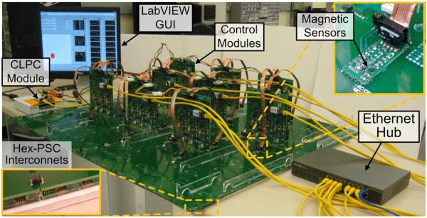
Characterization and bench-top testing setup of the EnerCage system.
A. Power Transfer Efficiency
Fig. 8 shows the calculated, simulated, and measured PTE results of two-, three-, and four-coil links versus coupling distance for a lateral misalignment of 48.5 mm between Tx and Rx coils and RL = 500 Ω. The PTE of the two-coil link, which is based on the coupling between L1 and L3 in Table I, is only reported for comparison with the three- or four-coil links in our design. The two-coil link has higher PTE at short distances (<50 mm) while three- and four-coil links provide higher PTE at larger coil separations (>60 mm). At 120 mm, the three- and four-coil links achieve measured PTEs of 6.2% and 5.6%, respectively, while the measured two-coil PTE is only 3.9%. The PTE of the four-coil link is lower than that of the three-coil link due to the additional loss in the L1–L2 link.
Fig. 8.
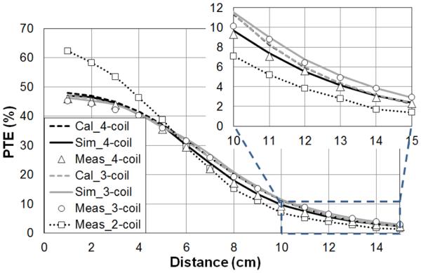
Comparison between PTE of the two-, three-, and four-coil links versus their coupling distance. The coil geometries of are reported in Table I.
B. In Vivo Experiment
Since the hex-PSCs that are on the edges of each rectangular stationary module need to be either geometrically completed or driven by the control modules of the neighboring stationary modules, we limited the experimental arena to the area that could be entirely powered by nine vertical control modules that formed a 3 × 3 array. This area includes 81 complete hex-PSCs that are identified by the solid black-bordered hexagons in Fig. 6, which indicate the active areas of these 81 hex-PSCs. Another limitation was imposed by the tracking algorithm that requires at least two magnetic sensors above and adjacent to each primary hex-PSC in order to verify that the tracer is located within the active area of that hex-PSC. Therefore, with 27 sensor modules, we had several primary hex-PSCs at the edge of the map (the white hexagons in Fig. 6), which were not activated by the PC station, even though the control modules had the ability to power them. Considering these limitations, the boundary of the experimental arena was established across the black dashed lines in Fig. 6 using transparent Plexiglas walls. The net active area, which was both inductively powered and magnetically tracked was 3538 cm2 (67 hex-PSCs), which to our knowledge is the largest wirelessly powered arena ever reported.
The assembled prototype mobile unit, which was designed to be removable from the headstage to prevent damage when the system was not in use, is shown in Fig. 9. A circular 4-layer PCB with L4 on the perimeter houses the MCU and other components including a 48 mm monopole antenna. The PCB is mounted on a hollow plastic cylinder that holds it 20 mm above the L3 base, which is molded in plastic (Smooth-Cast 300, Smooth-On, Easton, PA). Half of the magnetic tracer in installed under the PCB in the form of a ⊘8 mm × 1.5mm permanent magnet with residual surface flux density of Br max = 14 800 Gauss (K&J, Jamison, PA, USA), and weighing 0.8 g. The weight of the entire mobile unit was 9.8 g. The headstage consisted of a 25 mm stainless steel post (19-gauge cannula), shown on the right side of Fig. 9, with the other half of the magnetic tracer molded on top, allowing the mobile unit to be strongly secured on top of the subject's head by the force between the two halves of the magnetic tracer. The total weight of the post was 1.2 g. Using 3-D printing technology for the plastic parts, thin PCB, and on-chip integrated components, we can further reduce the weight of the headstage for adult male rats by half.
Fig. 9.
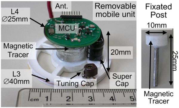
Removable mobile unit and the permanent steel post mounted on the rat's head. The mobile unit was held in place by the magnetic tracer.
A male Long-Evans rat weighing 570 g was used in our in vivo experiment, after all procedures were approved by the Institutional Animal Care and Use Committee (IACUC) at Emory University and the Georgia Institute of Technology. Aseptic stereotaxic surgery was performed after the rat was deeply anesthetized with isoflurane (1%–3% in oxygen) and given buprenor-phine (0.05 mg/kg) as an analgesic. Six stainless steel anchor screws were drilled into the lateral ridges of the rat's skull. The steel post was mounted vertically on the skull, secured by dental acrylic onto the anchor screws. A second injection of buprenor-phine (0.05 mg/kg) was administered the following day. The rat was allowed to recover for two weeks while carrying the post before testing began. Before the experiment, the mobile unit was placed on top of the post.
Fig. 10 shows the EnerCage in vivo experimental setup. The Tx_VD D for the PAs' supply voltage was being dynamically adjusted by the CLPC module in a closed-loop between 5 V and 18 V to change the PA power consumption between 0.5 W and 3.5 W depending on the position and orientation of the mobile unit. The experiment, which was conducted by placing the rat inside the experimental arena for 1 h and encouraging it to freely move around using chocolate-flavored pellets (Bio-Serv, Frenchtown, NJ), was meant to indicate whether the current EnerCage prototype placed in a realistic electrophysiology laboratory environment is capable of continuously delivering 20 mW to the headstage electronics at 4 V (an equivalent of RL = 500 Ω) without interruption. The results in Fig. 11(a), which show the changes in the Tx_VD D (upper black curve) and Vrec (lower blue curve) on the stationary (Tx) and mobile (Rx) units, respectively, over the course of the experiment proved our hypothesis to a satisfactory level.
Fig. 10.
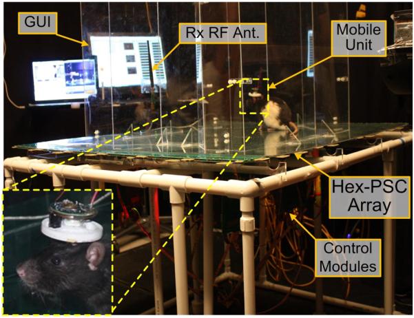
In vivo experimental setup for the EnerCage system in an electro-physiology laboratory. The insets show the animal subject (Long-Evans rat) carrying the mobile unit.
Fig. 11.
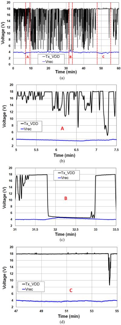
(a) In vivo experimental results showing the mobile unit rectifier voltage Vrec and the transmitter PA supply voltage, Tx_VD D during 1 h of a rat freely behaving in a 3538 cm2, wirelessly powered arena. (b) Period A: noise has corrupted the back telemetry data leaving a negative impact on the CLPC operation. (c) Period B: The minimum PA output power of 0.5 W is higher than what the mobile unit needs. (d) Period C: The mobile unit is held in a position with very low PTE, and the hex-PSCs cannot provide sufficient power to the mobile unit due to large distance and/or misalignment.
Fig. 11(b)–(d) zooms in on the 1 h time periods in Fig. 11(a), during which the EnerCage system showed less than perfect performance. In Fig. 11(b) (t = 5.5–7.5 min), Vrec has decreased but Tx_VD D has not been constantly maintained at its maximum value 18 V. This is likely caused by noise in the back telemetry data, misleading the operation of the CLPC module. In Fig. 11(c) (t = 31–33.5 min), Vrec has increased above 4 V, despite Tx_VD D staying at its minimum level (5 V). This occurs when the mobile unit is located very close to the surface of the stationary unit resulting in a coupling between the hex-PSCs and the Rx coils that was too strong. This problem can be resolved by allowing the Tx_VD D to go below 5 V or even temporarily turn off the PA. In Fig. 11(d) (t = 47–55 min), even though Tx_VD D is held at its maximum value of 18 V, Vrec is slightly below 4 V. This effect, which is the opposite of the effect in Fig. 11(c), is caused by the mobile unit being too far or sharply misaligned with respect to the stationary unit for more than 30 s, resulting in a PTE that was too low. This problem can be resolved by allowing the Tx_VD D to go above 18 V.
C. Other Animal Species
Size and weight of the mobile unit in the EnerCage system strongly depend on the nominal distance between its location over the course of the experiment to the stationary array of hex-PSCs at the bottom of the cage. The shorter the coils' distance, the same PTE can be achieved with smaller coils. Shorter distance also allows maintaining the magnetic field strength at the magnetic sensor array with smaller magnetic tracers. The nominal coils' distance depends on the animal species and the method and location of mobile unit attachment to the animal body, e.g., headstage, backpack, or implant. Thus, the size and weight of the mobile unit drops exponentially as it moves closer to the bottom of the EnerCage, from cats to rats, to mice, and even to insects. This makes the system usable among a wide range of animal species. Because the larger the animal, the more weight it can carry without affecting its behavior. Nevertheless, successful in vivo electrophysiology has been performed on rats with recording headstages weighing 30–50 g [46]. There are also methods to improve the coils' coupling to increase the PTE and further reduce the mobile unit size, aside from optimizing the coils' geometries [35], such as the use of ferrite and meta-material sheets under the stationary unit, which will be explored in the future [47].
VI. Conclusion
The modular architecture of the new EnerCage system takes advantage of multicoil coupling to reduce the number of control and sensing modules, while improving the PTE and localization accuracy. It demonstrated satisfactory performance in real time non-line-of-sight tracking, closed-loop wireless powering, and back telemetry data communication with a wirelessly powered mobile unit in the form of a removable headstage in both bench-top (dry lab) and in vivo (wet lab) experiments. The in vivo experiment on a small freely behaving animal subject (rat) showed 1-h uninterrupted operation of the current prototype by delivering 20 mW to the mobile unit in an actual electrophysiology lab environment. The mobile unit can replace batteries in any electronic or mechanical devices (e.g., infusion pumps) that are attached to or implanted in the animal body. The EnerCage system can deliver a designated amount of power (up to 20 mW) and bidirectional data using focused near-field inductive coupling at the FCC-approved 13.56 MHz over an unlimited experimental arena for an unlimited period of time without posing health risks to the researchers or interfering with other instruments in the same environment.
Furthermore, we intend to improve the accuracy of the magnetic localization algorithm, add adaptive impedance-matching to the Tx unit, and adaptive tuning capability to the mobile Rx unit. We also intend to use the system in a behavioral neuroscience experiment, in which neural data is collected during wireless powering.
Acknowledgment
The authors would like to thank C.D. Emelue for his help with the Ethernet communication and other members of the GT-Bionics Laboratory for their help with the measurements as well as J. Trimper and R. Stefanescu for their help with the animal experiments.
This work was supported in part by the National Institutes of Health, NIBIB, under Grant 1R21EB009437-01A1 and in part by the National Science Foundation under Award ECCS-824199.
Biographies

Uei-Ming Jow (S'07) received the B.E. degree in electrical engineering from Tatung University, Taipei, Taiwan, in 1999, and the M.S. degree in electronic engineering from the National Taiwan University of Science and Technology, Taipei, in 2001, and the Ph.D. degree in electronic engineering from the Georgia Institute of Technology, Atlanta, USA, in 2013.
From 2001 to 2006, he was with the Industrial Technology Research Institute in Hsinchu, Taiwan, as an RF engineer in the Electronics Research and Service Organization. He was involved in the analysis of electromagnetic compatibility for the high speed digital circuit as well as the embedded RF circuit packaging technology. From 2007 to 2013, he was involved in research related to neural engineering, bionic systems, integrated analog circuit design, and wireless implantable biomedical systems. He was involved in wireless power transmission systems and antenna design.

Peter McMenamin (S'12) received the B.A. degree in economics from the Johns Hopkins University, MD, USA, in 2005, and the B.S. degree in electrical and computer engineering from the Georgia Institute of Technology, Atlanta, USA, in 2012, where he is currently working toward the Ph.D. degree.
He joined the GT-Bionics Lab in the summer of 2011 as an undergraduate, where he is currently involved in wireless power and data transmission to implantable devices. He is a member of Eta Kappa Nu and Gamma Beta Phi.
Mehdi Kiani (S'09) received the B.S. degree from Shiraz University, Shiraz, Iran, in 2005, and the M.S. degree from Sharif University of Technology, Tehran, Iran, in 2008. He is currently working toward the Ph.D. degree from GT-Bionics Lab, Georgia Institute of Technology, Atlanta, USA.

Joseph R. Manns received the Ph.D. degree in psychology from the University of California, San Diego, USA, in 2002.
After completing a Postdoctoral Fellowship at Boston University in 2007, he joined the Faculty at Emory University, where he is currently an Assistant Professor in the Department of Psychology.
Dr. Manns was awarded a postdoctoral Ruth L. Kirschstein National Research Service Award (2003–2006) and a Pathway to Independence Award (K99/R00; 2006–2011) by the National Institutes of Health.

Maysam Ghovanloo (S'00–M'04–SM'10) was born in Tehran, Iran, in 1973. He received the B.S. degree in electrical engineering from the University of Tehran, Tehran, in 1994, the M.S. degree in biomedical engineering from the Amirkabir University of Technology, Tehran, in 1997, and the M.S. and Ph.D. degrees in electrical engineering from the University of Michigan, Ann Arbor, USA, in 2003 and 2004, respectively.
From 2004 to 2007, he was an Assistant Professor in the Department of Electrical and Computer Engineering, NC-State University, Raleigh, NC, USA. He joined the Faculty of Georgia Institute of Technology, Atlanta, USA, in 2007, where he is currently an Associate Professor and the Founding Director of the GT-Bionics Lab, School of Electrical and Computer Engineering. He has authored or coauthored more than 100 peer-reviewed publications.
Dr. Ghovanloo is an Associate Editor of the IEEE Transactions on Biomedical Engineering, IEEE Transactions on Biomedical Circuits and Systems, and a member of the Imagers, MEMS, Medical, and Displays (IMMD) subcommittee at the International Solid-State Circuits Conference (ISSCC). He is the 2010 recipient of a CAREER award from the National Science Foundation. He has organized several special sessions and was a member of Technical Review Committees for major conferences in the areas of circuits, systems, sensors, and biomedical engineering. He is a member of the Tau Beta Pi, AAAS, Sigma Xi, and the IEEE Solid-State Circuits Society, IEEE Circuits and Systems Society, and IEEE Engineering in Medicine and Biology Society.
References
- [1].Rosenzweig M, Breedlove S, Watson N. Biological Psychology: An Introduction to Behavioral and Cognitive Neuroscience. 4th ed. Sinauer Associates; Sunderland, MA, USA: 2004. [Google Scholar]
- [2].Donoghue JP. Bridging the brain to the world: A perspective on neural interface systems. Neuron. 2008 Nov;60(3):511–521. doi: 10.1016/j.neuron.2008.10.037. [DOI] [PubMed] [Google Scholar]
- [3].Plexon Inc. Plexon's headstages for multi-channel neuronal recording. 2013 Aug 25; [Online]. Available: http://www.plexon.com/products/headstages.
- [4].Rosenzweig MR, Bennett EL. Psychobiology of plasticity: Effects of training and experience on brain and behavior. Behav. Brain Res. 1996 Jun;78(1):57–65. doi: 10.1016/0166-4328(95)00216-2. [DOI] [PubMed] [Google Scholar]
- [5].Kempermann G, Kuhn H, Gage F. More hippocampal neurons in adult mice living in an enriched environment. Nature. 1997 Apr;386(6624):493–495. doi: 10.1038/386493a0. [DOI] [PubMed] [Google Scholar]
- [6].Van Praag H, Kempermann G, Gage FH. Neural consequences of environmental enrichment. Nat. Rev. Neuroscience. 2000 Dec;1:191–198. doi: 10.1038/35044558. [DOI] [PubMed] [Google Scholar]
- [7].Belayev A, Saul I, Liu Y, Zhao W, Ginsberg M, Valdes M, Busto R, Belayev L. Enriched environments delays the onset of hippocampal damage after global cerebral ischemia in rats. Brain Res. 2003 Feb;964(1):121–127. doi: 10.1016/s0006-8993(02)04089-1. [DOI] [PubMed] [Google Scholar]
- [8].Brauner A, Kurjiaka D, Ibragimov A, Baldwin A. Impact of cage size and enrichment (tube and shelf) on heart rate variability in rats. Scand. J. Lab. Anim. Sci. 2010 Oct;37(3):185–201. [Google Scholar]
- [9].Mohammed AH, Zhu SW, Darmopil S, Hjerling-Leffler J, Ernfors P, Winblad B, Diamond MC, Eriksson PS, Bogdanovic N. Environmental enrichment and the brain. Prog. Brain Res. 2002 Dec;138:109–33. doi: 10.1016/S0079-6123(02)38074-9. [DOI] [PubMed] [Google Scholar]
- [10].Petrosinia L, DeBartoloa P, Fotia F, Gelfoc F, Cutulia D, Leggioa MG, Mandolesic L. On whether the environmental enrichment may provide cognitive and brain reserves. Brain Res. Rev. 2009 Oct;61(2):221–239. doi: 10.1016/j.brainresrev.2009.07.002. [DOI] [PubMed] [Google Scholar]
- [11].Sale A, Berardi N, Maffei L. Enrich the environment to empower the brain. Trends. Neuroscience. 2009 Apr;32(4):233–239. doi: 10.1016/j.tins.2008.12.004. [DOI] [PubMed] [Google Scholar]
- [12].Triangle BioSystems International TBSI NeuroWare. 2013 Aug 25; [Online]. Available: http://www.trianglebiosystems.com/neuroware%C2%A9.html.
- [13].Sodagar AM, Perlin GE, Yao Y, Najafi K, Wise KD. An implantable 64-channel wireless microsystem for single-unit neural recording. IEEE J. Solid-State Circuits. 2009 Sep;44(9):2591–2604. [Google Scholar]
- [14].Szuts TA, Fadeyev V, Kachiguine S, Sher A, Grivich MV, Agrochao M, Hottowy P, Dabrowski W, Lubenov EV, Siapas AG, Uchida N, Litke AM, Meister M. A wireless multi-channel neural amplifier for freely moving animals. Nature Neurosci. 2011 Feb;14(2):263–269. doi: 10.1038/nn.2730. [DOI] [PubMed] [Google Scholar]
- [15].Greenwald E, Mollazadeh M, Hu C, Tang W, Culurciello E, Thakor NV. A VLSI neural monitoring system with ultra-wideband telemetry for awake behaving subjects. Trans. Biomed. Circuits Syst. 2011 Apr;5(2):112–119. doi: 10.1109/TBCAS.2011.2141670. [DOI] [PubMed] [Google Scholar]
- [16].Fan D, Rich D, Holtzman T, Ruther P, Dalley JW, Lopez A, Rossi MA, Barter JW, Salas-Meza D, Herwik S, Holzhammer T, Morizio J, Yin HH. A wireless multi-channel recording system for freely behaving mice and rats. PLoS One. 2011 Jul;6(7):1–9. doi: 10.1371/journal.pone.0022033. [DOI] [PMC free article] [PubMed] [Google Scholar]
- [17].Lee SB, Yin M, Manns JR, Ghovanloo M. A wideband dual-antenna receiver for wireless recording from animals behaving in large arenas. IEEE Trans. Biomed. Eng. 2013 Jul;60(17):1993–2004. doi: 10.1109/TBME.2013.2247603. [DOI] [PMC free article] [PubMed] [Google Scholar]
- [18].Wentz CT, Bernstein JG, Monahan P, Guerra A, Rodriguez A, Boyden ES. A wirelessly powered and controlled device for optical neural control of freely-behaving animals. J. Neural Eng. 2011 Jun;8(4):424–436. doi: 10.1088/1741-2560/8/4/046021. [DOI] [PMC free article] [PubMed] [Google Scholar]
- [19].Nikitin PV, Rao KVS, Lazar S. An overview of near field UHF RFID. Proc. Intl. Conf. RFID.Mar, 2007. pp. 167–174. [Google Scholar]
- [20].Yeager DJ, Holleman J, Prasad R, Smith JR, Otis BP. Neural-WISP: An energy-harvesting wireless neural interface with 1-m range. IEEE Trans. Biomed. Circuits Syst. 2009 Dec;3(6):379–387. doi: 10.1109/TBCAS.2009.2031628. [DOI] [PubMed] [Google Scholar]
- [21].Peng CC, Xiao Z, Bashirullah R. Toward energy efficient neural interfaces. IEEE Trans. Biomed. Eng. 2009 Nov;56(11):2697–2700. doi: 10.1109/TBME.2009.2029704. [DOI] [PubMed] [Google Scholar]
- [22].Thomas SJ, Harrison RR, Leonardo A, Reynolds MS. A battery-free multichannel digital neural/EMG telemetry system for flying insects. IEEE Trans. Biomed. Circuits Syst. 2012 Oct;6(5):424–436. doi: 10.1109/TBCAS.2012.2222881. [DOI] [PubMed] [Google Scholar]
- [23].Kim T, McCall JG, Jung YH, Huang X, Siuda ER, Li Y, Song J, Song YM, Pao HA, Kim R-H, Lu C, Lee SD, Song I-S, Shin G, Al-Hasani R, Kim S, Tan MP, Huang Y, Omenetto FG, Rogers JA, Bruchas MR. Injectable, cellular-scale optoelectronics with applications for wireless optogenetics. Science. 2013 Apr;340(7):211–216. doi: 10.1126/science.1232437. [DOI] [PMC free article] [PubMed] [Google Scholar]
- [24].OET Bulletin 65: Evaluating Compliance with FCC Guidelines for Human Exposure to Radiofrequency Electromagnetic Fields. Federal Commun. Commission; Washington, DC, USA: Aug, 1997. [Google Scholar]
- [25].Mini Mitter Minimitter animal monitoring. 2013 Aug 25; 2013. [Online]. Available: http://minimitter.respironics.com/animal_products.cfm.
- [26].Millar Instruments, Inc. TRM telemetry system. 2013 Aug 25; [Online]. Available: http://millar.com/products/telemetry.
- [27].PhenoSys GmbH Social Activity Monitor. 2013 Aug 25; [Online]. Available: http://www.phenosys.com/index.php/en/products/sam.
- [28].McCormick D, Hu AP, Nielsen P, Malpas S, Budgett D. Powering implantable telemetry devices from localized magnetic fields. Proc. IEEE Eng. Med. Biomed. Cir. Soc. Conf; Aug, 2007. pp. 2331–2335. [DOI] [PubMed] [Google Scholar]
- [29].Russell D, McCormick D, Taberner A, Nielsen P, Hu P, Budgett D, Lim M, Malpas S. Wireless power delivery system for mouse telemeter. Proc. IEEE Biomed. Circ. Sys. Conf.Nov, 2009. pp. 273– 276. [Google Scholar]
- [30].Hui SYR, Ho WWC. A new generation of universal contact-less battery charging platform for portable consumer electronic equipment. IEEE Trans. Power Electron. 2005 May;20(3):620–627. [Google Scholar]
- [31].Waffenschmidt E, Staring T. Limitation of inductive power transfer for consumer applications. Proc. Eur. Conf. Power Electron. Appl..Sep, 2009. pp. 1–10. [Google Scholar]
- [32].Wireless Power Consortium Qi low power specification. 2013 Aug 25; [Online]. http://www.wirelesspowerconsortium.com/developers/specification.html.
- [33].Jow U, Kiani M, Huo X, Ghovanloo M. Towards a smart experimental arena for long-term electrophysiology experiments. IEEE Trans. Biomed. Circuits Syst. 2012 Oct;6(5):414–423. doi: 10.1109/TBCAS.2012.2211872. [DOI] [PMC free article] [PubMed] [Google Scholar]
- [34].Lee SB, Lee HM, Kiani M, Jow U, Ghovanloo M. An inductively powered scalable 32-channel wireless neural recording system-ona-chip for neuroscience applications. IEEE Trans. Biomed. Circuits Syst. 2010 Dec;4(6):360–371. doi: 10.1109/TBCAS.2010.2078814. [DOI] [PMC free article] [PubMed] [Google Scholar]
- [35].Jow U, Ghovanloo M. Geometrical design of a scalable overlapping planar spiral coil array to generate a homogeneous magnetic field. IEEE Trans. Mag. 2013 Jun;49(6):2933–2945. doi: 10.1109/TMAG.2012.2235181. [DOI] [PMC free article] [PubMed] [Google Scholar]
- [36].Kiani M, Ghovanloo M. An RFID-based closed loop wireless power transmission system for biomedical applications. IEEE Trans. Circuits Syst. II, Exp. Briefs. 2010 Apr;57(4):260–264. doi: 10.1109/TCSII.2010.2043470. [DOI] [PMC free article] [PubMed] [Google Scholar]
- [37].McMenamin P, Jow U, Kiani M, Ghovanloo M. Real time control of a wireless powering and tracking system for long-term and large-area electrophysiology experiments. Proc. IEEE Biomed. Circ. Sys. Conf..Nov, 2012. pp. 240–243. [Google Scholar]
- [38].Kiani M, Jow U, Ghovanloo M. Design and optimization of a 3-coil inductive link for efficient wireless power transmission. IEEE Trans. Biomed. Circuits Syst. 2011 Dec;5(6):579–591. doi: 10.1109/TBCAS.2011.2158431. [DOI] [PMC free article] [PubMed] [Google Scholar]
- [39].Kiani M, Ghovanloo M. The circuit theory behind coupled-mode magnetic resonance based power transmission. IEEE Trans. Circuits Syst. I, Reg. Papers. 2012 Sep;59:2065–2074. doi: 10.1109/TCSI.2011.2180446. [DOI] [PMC free article] [PubMed] [Google Scholar]
- [40].Kurs A, Karalis A, Moffatt R, Joannopoulos JD, Fisher P, Soljacic M. Wireless power transfer via strongly coupled magnetic resonances. Sci. Exp. 2007 Jul;317:83–86. doi: 10.1126/science.1143254. [DOI] [PubMed] [Google Scholar]
- [41].RamRakhyani AK, Mirabbasi S, Chiao M. Design and optimization of resonance-based efficient wireless power delivery systems for biomedical implants. IEEE Trans. Biomed. Circuits Syst. 2011 Feb;5(1):48–63. doi: 10.1109/TBCAS.2010.2072782. [DOI] [PubMed] [Google Scholar]
- [42].Jow U, Ghovanloo M. Design and optimization of printed spiral coils for efficient transcutaneous inductive power transmission. IEEE Trans. Biomed. Circuits Syst. 2007 Sep;1(3):193–202. doi: 10.1109/TBCAS.2007.913130. [DOI] [PubMed] [Google Scholar]
- [43].Zierhofer CM, Hochmair ES. Geometric approach for coupling enhancement of magnetically coupled coils. IEEE Trans. Biomed. Eng. 1996 Jul;43(7):708–714. doi: 10.1109/10.503178. [DOI] [PubMed] [Google Scholar]
- [44].Charles River Laboratories International, Inc. Research animal, Long-Evans rat. 2013 Aug 25; [Online]. Available: http://www.criver.com/en-US/ProdServ/ByType/ResModOver/ResMod/Pages/Long-EvansRat. aspx.
- [45].Chang C, Huo X, Ghovanloo M. Towards a magnetic localization system for 3-D tracking of tongue movements in speech-language therapy. Proc. IEEE Eng. Med Biol. Soc. 2009 Sep;:563–566. doi: 10.1109/IEMBS.2009.5334058. [DOI] [PMC free article] [PubMed] [Google Scholar]
- [46].Manns JR, Eichenbaum H. A cognitive map for object memory in the hippocampus. Learning Memory. 2009 Jul;16:616–624. doi: 10.1101/lm.1484509. [DOI] [PMC free article] [PubMed] [Google Scholar]
- [47].Choi J, Seo C. High-efficiency wireless energy transmission using magnetic resonance based on negative refractive index metamaterial. Prog. Electromagn. Res. 2010 Jun;106:33–47. [Google Scholar]


