Abstract
Oblique back-illumination microscopy (OBM) provides high resolution, sub-surface phase-gradient images from arbitrarily thick samples. We present an image formation theory for OBM and demonstrate that OBM lends itself to volumetric imaging because of its capacity for optical sectioning. In particular, OBM can provide extended depth of field (EDOF) images from single exposures, by rapidly scanning the focal plane with an electrically tunable lens. These EDOF images can be further enhanced by deconvolution. We corroborate our theory with experimental volumetric images obtained from transparent bead samples and mouse cortical brain slices.
OCIS codes: (110.0180) Microscopy, (350.5030) Phase, (120.5050) Phase measurement
1. Introduction
Phase contrast microscopy provides exquisite high-resolution images of sample morphology, without the use of sample labeling. However, standard phase contrast techniques, like differential interference contrast (DIC), only work in the transmission direction and thus cannot be used when imaging thick samples (see [1] for review). Because many applications, such as in-vivo small animal imaging, require the use of thick tissues, a method of obtaining phase contrast from thick tissues is highly desirable.
We have recently developed a new technique called Oblique Back-illumination Microscopy (OBM) that provides microscopic resolution DIC-like images of sub-surface sample morphology in arbitrarily thick tissue [2]. OBM has a similar layout to a standard camera-based reflection microscope, the only difference being the manner in which illumination is delivered to the sample. In standard epi-detection microscopy, illumination is delivered via an objective and back-reflected light is collected through this same objective. In OBM, illumination is delivered via two diametrically opposed off-axis light sources just outside the objective housing. When the sample is thick, this illumination undergoes multiple scattering and is re-directed in the backward direction. A portion of this backscattered light is collected by the objective and ultimately imaged by the camera. Because the light sources are off axis, the collected illumination traverses the focal plane in an oblique manner, leading to phase-gradient contrast [3–5]. Using two diametrically opposed light sources enables the acquisition of sequential images with opposing illumination obliquity, which makes it possible to separate phase contrast from amplitude contrast [6].
Our previous work on OBM made use of contact-mode endomicroscope configurations [2,7]. Here, we apply OBM in a standard microscope configuration. We develop a simplified theory of OBM, and characterize its optical sectioning capacity. This theory is generalized to 3D imaging for extended samples. We illustrate the capacity of OBM to provide both fast volumetric imaging from multiple exposures and extended depth of field (EDOF) imaging from single exposures. These techniques are corroborated by experiments with transparent bead samples in scattering media and unlabeled mouse brain slices.
2. OBM theory
Though it is configured in a reflection geometry, OBM is actually a transmission microscope in disguise. That is, the multiply scattered light dominantly illuminates the focal plane from the back rather than from the front. As such, OBM may be modeled as a simple, camera-based transmission microscope with the particularity that the illumination, while being largely spatially incoherent, is oblique. Defining CSF( ) to be the coherent spread function (or amplitude point spread function) of the transmission microscope, the image intensity incident on the camera is given by [1, chapter 10]
| (1) |
where is the complex sample transmittance and corresponds to lateral sample coordinates at the focal plane. The illumination is assumed to be quasi-homogeneous, meaning that its mutual intensity may be written as Isμ±( ) where Is is the illumination intensity, which is roughly uniform throughout the field of view, and μ±( ) are the illumination coherence functions [1, chapter 10], associated with illumination injected into the sample from the right (+) or from the left (−) of the objective.
Experimentally, we have found that the illumination is close to Lambertian in angular profile, though with a mean tilt angle θt of a few tens of degrees [2]. Thus, we may write,
| (2) |
where μL( ) is the coherence function associated with a symmetrically distributed Lambertian source, and the exponential term introduces phenomenological tilt angles whose signs depend on which illumination source is active. The tilts are taken to be along the x direction. κ is the mean wavenumber of the illumination in the sample.
Applying the coordinate transformation and , we have
| (3) |
where is the sample mutual transmittance.
Because a Lambertian source is almost fully incoherent, its coherence function μL( ) is expected to be very narrow, on the order of a wavelength [8]. We may therefore adopt the following approximations, valid to first order in :
| (4) |
| (5) |
where PSF( ) is the microscope incoherent point spread function.
We arrive at
| (6) |
| (7) |
where we have introduced the constant prefactors
| (8) |
| (9) |
The advantage of operating OBM with diametrically opposed illumination sources is that the amplitude and phase-gradient contrast are separable. Defining ΣI( ) = I+( ) + I−( ) and ΣI( ) = I+( ) − I−( ), an amplitude contrast image is estimated by ΣI( ), while a phase-gradient contrast image is estimated by ΔI( )/ΣI( ). Henceforth, we will consider only non-absorbing samples, meaning that |t( )| ≈ 1 and ΣI( ) is roughly constant throughout the field of view. We will therefore focus our discussion only on ΔI( ).
Equation (7) characterizes the capacity of OBM to image phase-gradients. We emphasize that the term “phase” here refers to phase shifts induced by the sample, rather than to optical phases (which are ill defined for spatially incoherent light). Thus OBM produces images of sample-induced phase gradients in the same manner that standard widefield microscopy produces images of fluorescence, namely as a convolution with the microscope PSF.
As written, Eq. (7) describes how phase-gradients at the focal plane are projected onto the camera plane. That is, Eq. (7) corresponds to 2D imaging. It is a simple matter to generalize this to 3D by extending the PSF along the axial direction, z, following the 3D aperture approach introduced by McCutchen [9]. In this case, we model the sample as an extended phase object comprising a stack of thin phase planes of differential thickness dz0, and we assume that the intensity contribution from each plane is independent. This approximation is justified for two reasons. First, the illumination we use is broadband and hence temporally incoherent with a coherence length on the order of a few wavelengths; second, as we will see below, OBM provides optical sectioning.
We arrive at
| (10) |
or equivalently
| (11) |
where the tilde indicates a Fourier-transform with respect to x and y, and = 〈κx, κy〉 is the Fourier conjugate variable of . OTF( ;z) is the microscope 2D optical transfer function as a function of defocus z.
Equations (10) and (11) are the main results of this section. As noted above, phase-gradients are imaged as incoherent objects. However, it is well known that standard incoherent wide-field microscopy does not provide optical sectioning because low frequency sample structure cannot be axially resolved. As an example, let us consider fluorescence microscopy. Fluorescence must be a positive definite quantity, meaning that fluorescent samples must exhibit low frequency structure (as low as zero-frequency). The situation is different for OBM because it images phase gradients and not phase. These gradients do not contain low spatial frequencies, and as such they can be axially resolved. We can estimate the optical sectioning strength of OBM by examining Eq. (11). We observe that the term κx in the integral indeed quenches low spatial frequencies, enabling OTF( ;z) to perform optical sectioning. In fact, this mechanism of optical sectioning is identical to that occasioned by dynamic speckle illumination microscopy with wavelet prefiltering [10]. We thus expect the same sectioning strength for OBM, namely a scaling of phase-gradient signal as z−3/2 with large defocus (for a circular detection aperture). Such a scaling law is almost as strong as the sectioning strength of a confocal microscope, where signal decays as z−2. We exploit the optical sectioning capability of OBM to perform volumetric phase-gradient imaging.
3. Fast volumetric imaging
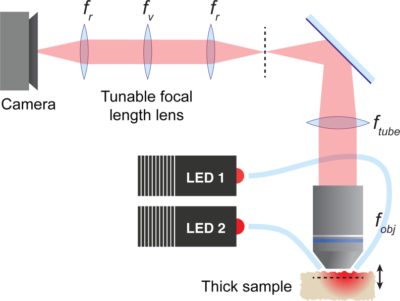
Our OBM setup is illustrated in Fig. 1. This is a standard widefield microscope (objective: Olympus 40× LCPlanFl NA=0.8 water; tube lens 180 mm) where a focal plane (horizontal dashed line) is imaged onto an intermediate image plane (vertical dashed line). Here, we have inserted an additional ×1 relay system to re-image the intermediate image to the camera. The purpose of this relay system is described below.
Fig. 1.
(Color online) OBM with a tunable lens relay system. A focal plane in the sample (horizontal dashed line) is imaged to an intermediate plane (vertical dashed line) and reimaged to a camera. The tunable lens of focal length fv is in an aperture plane, enabling a rapid tuning of the focal plane depth without moving the sample. Alternating LED light is launched into the sample via two off-axis fibers (only a single fiber is shown active).
The principle of OBM is to back-illuminate the focal plane with back-scattered illumination that has been injected into the sample off axis. The illumination in our case is provided by two LEDs (Mightex 4-LED WFC, using a single 625 nm channel), delivered by 1 mm plastic optical fibers (Thorlabs BFL48-1000). These fibers are held 7 mm apart by a support ring (not shown) so that they are almost in contact with the sample. The ring is large enough that the microscope objective can freely move up and down to provide coarse focus adjustment. The power at each fiber output was roughly 9 mW.
To perform fast volumetric imaging it is necessary to have a fast focusing mechanism. Conventionally, image focus is controlled by varying the height of the sample or the objective, however these approaches involve mechanical translations that are slow and can cause vibrations. We take advantage here of new technology provided by electrically tunable liquid lenses. These provide focal lengths that can be controlled rapidly without causing vibrations. Ideally, these should be inserted in the aperture plane of an imaging system, since in this plane they provide focus control without modifying magnification or telecentricity. Unfortunately, in a standard microscope the aperture plane is located within the objective housing. The purpose of our additional ×1 relay system is to provide access to an aperture plane.
Simple ray tracing provides the relation between the focal length of the tunable lens fv and the displacement of the focal plane within the sample zv. This is given by
| (12) |
where M = ftube/fobj is the magnification of the microscope, fr is the focal length of the relay lenses, and ns is index of refraction of the sample. This expression may also be found in [11].
The tunable lens used in our setup (Optotune EL-10-30-C) can vary its focal length between −600 mm and 75 mm. An advantage of this lens is that its focusing power (1/fv) varies roughly linearly with voltage applied to the lens, meaning that zv also varies linearly. We found that imaging quality remained adequate over a zv scan range of about 100 μm, beyond which aberrations introduced by the variable lens became unacceptable. The resonant frequency of the lens was specified by the manufacturer to be about 380 Hz. In the case of volumetric imaging, we operated the lens with a sawtooth control voltage of frequency up to about 100 Hz.
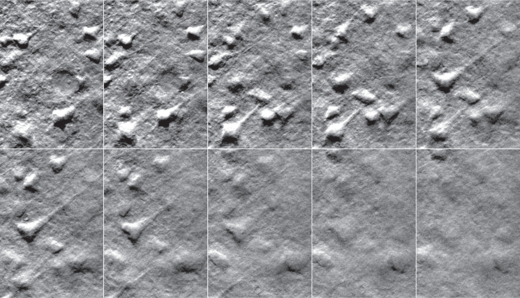
Figure 2 ( Media 1 (3MB, AVI) ) illustrates a z-stack of phase-gradient images obtained from a thick (2 mm) slab of freshly-excised, unlabeled mouse cortex. The tissue was immersed in PBS during imaging. Pyramidal neurons are clearly visible and manifestly axially resolved, as expected.
Fig. 2.
OBM phase-gradient images of mouse pyramidal neurons demonstrating optical sectioning. The frames are selected from a z-stack obtained by scanning the tunable lens ( Media 1 (3MB, AVI) ). The images were taken at equal intervals along a span of 42 μm (displayed here at intervals of 4.7 μm) at increasing depths from top-left to bottom-right. The field of view for each image is 67×96 μm. The total exposure time per frame was 20 ms (10 ms per active LED).
4. Extended depth of field (EDOF)
When working with microscopes that feature optical sectioning, the ability to quickly view a sample with an extended depth of field is often desirable because it provides a global view of the sample within a single shot. A variety of strategies exist for EDOF microscopy, most of which involve introducing phase variations in the aperture (see [12] for review). Alternatively, EDOF microscopy can be performed by rapidly scanning the focal plane during the camera exposure (as opposed to between exposures). Such a strategy for EDOF is well known in the photography community [13, 14]. With the advent of methods for rapid focal-plane scanning, this technique is now being applied to microscopy [11, 15, 16].
A difficulty with applying EDOF to standard microscopes is that these do not provide optical sectioning. As such, EDOF images are highly blurred and/or distorted, and a deconvolution step is required to recover corrected images. In general, such deconvolution is highly sensitive to noise and requires a detailed knowledge of the microscope PSF and focal scan range. In the case of microscopes that provide optical sectioning, the application of EDOF is much more straightforward since signals from one depth do not contaminate signals from another. That is, an EDOF image may be obtained by simply adding the signals from different depths. This strategy was used, for example, in [11]. In our case, phase-gradient OBM provides some degree of optical sectioning. We may therefore expect the application of EDOF to phase-gradient OBM to be straightforward.
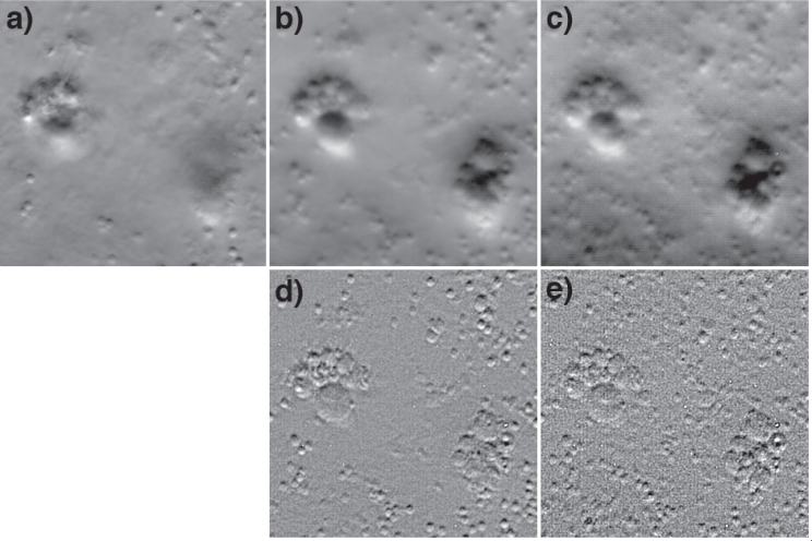
To demonstrate this, we made use of a sample of polystyrene beads (2 μm) and glass beads (size range 3–10 μm, Polysciences 07666) embedded in a thick slab of agarose gel. Figure 3(a) is a phase-gradient OBM image of these beads acquired at a depth of about 50 μm. Figures 3(b) and 3(c) are EDOF images acquired by rapidly modulating the tunable lens with focal-plane scan ranges 25 μm and 100 μm, respectively. The exposure time per active LED was 10 ms, and the tunable lens was modulated at 100 Hz. That is, the EDOF images are superpositions of signals obtained from their respective full focal-plane scan ranges. As expected, more and more beads become visible as the depth of field is extended. Perhaps less expected, however, is the presence of the concomitant blurring. There are a variety of explanations for this blurring. First, blurring increases with depth penetration because of aberrations introduced by the sample interface and by inhomogeneities caused by overlying beads themselves. These aberrations cannot be corrected by our setup and are thus unavoidable in our EDOF images. Second, the same exposure time was used in all cases. That is, constituent planes within the EDOF images received significantly less light than associated planes acquired with full exposure, undermining the SNR in the EDOF image (more on this later). Third, although we have claimed that phase-gradient OBM exhibits optical sectioning, the strength of this optical sectioning is modest. As noted above, it is weaker than confocal, and as a result some blurring may be expected in our EDOF images.
Fig. 3.
EDOF images of polystyrene (2 μm) and glass (3–10 μm) beads embedded in agarose gel. Panel a is a standard OBM phase-gradient image. Panels b,c are EDOF phase-gradient images acquired in single exposures by scanning the focal plane over ranges 25 μm and 100 μm respectively. Panels d,e are the same EDOF images, but deblurred according to Eq. (18). The field of view for all panels is 63×63 μm.
To characterize the degree of EDOF blurring, we consider the effective PSF associated with an EDOF image obtained from a focal scan range D. This is given by
| (13) |
which can be expressed equivalently as an effective OTF
| (14) |
| (15) |
where Δκ⊥ = 2NA/λ is the diffraction-limited cutoff frequency of our microscope, κ⊥ = | |, and jinc(z) = 2J1(z)/z where J1 is the first order cylindrical Bessel function. To arrive at Eq. (15), we made use of the Stokseth approximation for a defocused OTF with a circular aperture [17]. We note that the OTF here is normalized such that OTF(0;0) = 1.
If D is large then OTFEDOF( ;z) becomes approximately independent of z, and the integral in Eq. (15) may be estimated by extending its limits to infinity. With the additional approximation OTF(κ⊥;0) ≈ (1 − κ⊥/Δκ⊥) we arrive at
| (16) |
leading to finally
| (17) |
We observe that OTFEDOF diverges as κ⊥ → 0 because we have extended the limits of the integral in Eq. (15) to infinity. In reality, we expect OTFEDOF( = 0) → D for a finite scan range. In any case, we conclude that OTFEDOF acts as a lowpass filter. Such filtering leads to blurring of the EDOF image, which is particularly problematic when applied to conventional widefield microscopy, but less problematic for OBM since it is a differential technique. In other words, the κx in the numerator of equation 17 largely compensates for the divergence caused by κ⊥ in the denominator. Nevertheless, OTFEDOF does lead to some blurring with OBM, as is apparent in Figs. 3(b)–3(c).
To help mitigate this problem of blurring, we may invoke deconvolution. For example, to compensate for the lowpass blurring function given by Eq. (17), we may simply multiply ΔĨEDOF( ) by a highpass deblurring function.
| (18) |
This function has been arbitrarily scaled to have no effect outside the diffraction limit, and roughly accounts for the fact that D is finite. The result of such deblurring is shown in Figs. 3(d)–3(e). It is apparent that much of the blurring in Figs. 3(b)–3(c) is compensated for.
Some words of caution are in order. Our derivation of Eq. (18) invoked several approximations. As is well known, image deblurring is very sensitive to the exact form of the deconvolution kernel, and inaccuracies in this kernel can lead to artifacts. Such artifacts are likely to be present in Figs. 3(e)–3(f). Moreover, it is also known that the Stokseth approximation for the defocused OTF may be inaccurate for large defocus values [18], presenting another potential source of artifacts. Certainly more sophisticated deconvolution algorithms would provide more accurate results. We have limited our goal here to demonstrating that phase-gradient OBM is a promising candidate for EDOF by single-exposure focal scanning.
5. 3D imaging
A common problem is how to display a volumetric stack of optically sectioned images. Popular techniques include generating a series of maximum value projections along different directions, displaying the stack from different perspectives. This technique is effective for positive definite images, such a fluorescence images, but does not work well for phase-gradient images because they contain negative values. One may spatially integrate phase-gradient images in the hope of reconstructing phase, though with gradient information only along one axis such an integration is ill-defined. A makeshift solution has been proposed using the Hilbert transform to perform pseudo-integration [19].
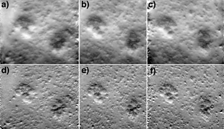
Here, we describe a technique to display a stack of phase-gradient images directly, without the use of an integration step. We exploit the fact that phase-gradient images are naturally amenable to EDOF by single-exposure focal scanning; the key is to recognize that EDOF images are not maximum intensity projections but rather integrated (or mean) intensity projections. This is demonstrated with a stack of bead images (same sample as in Fig. 3). A summation of the images over an axial range of 82 μm leads to Fig. 4(b), corresponding to an integrated intensity projection along the z-axis. We note that this EDOF image is of higher quality than that in Fig. 3 for two reasons. First, Fig. 4(b) was synthesized from multiple exposures. The light dosage for Fig. 4(b) was thus significantly greater than for Fig. 3, which was obtained from a single exposure, leading to a significantly enhanced SNR. Second, because phase-gradient OBM provides some degree of optical sectioning, we expect EDOF-induced blurring to arise mostly from nearest neighbor image planes. Figure 4 was generated from a discrete stack of images whereas Fig. 3 was generated from a continuous stack. We thus expect the problem of blurring from nearest neighbor planes to be somewhat abated in Fig. 4.
Fig. 4.
Integrated intensity projections from a phase-gradient z-stack of beads in agarose gel (same sample as in Fig. 3). Panel b is a projection along the z-direction. Panels a,c are projections from ± 10° tilt directions (animation in Media 2 (906.5KB, AVI) ). Panels d–f are the same as the top row, but deblurred according to Eg. 18 (animation in Media 3 (1.7MB, AVI) ). The projections are generated from a 63×63×82 μm3 volume.
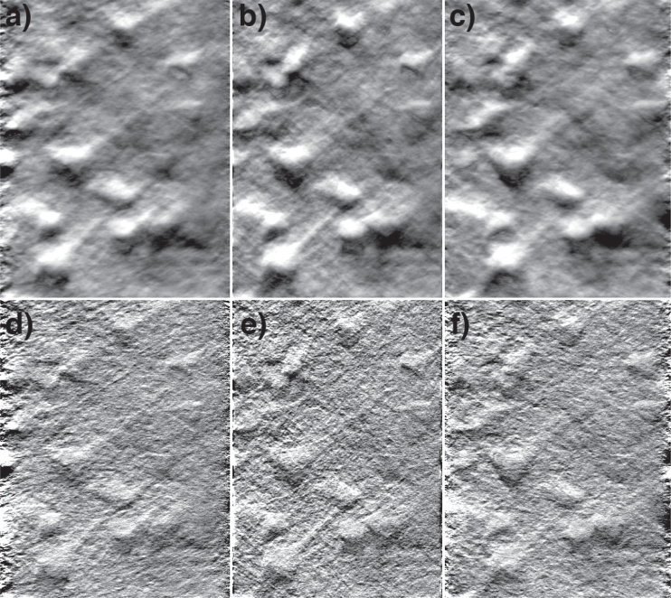
Figures 4(a)–4(c), illustrate integrated intensity projections along axes that are tilted off axis with tilt angles orthogonal to the phase-gradient axis. These may be interpreted as EDOF images. An animation from a range of tilt axes is available in Media 2 (906.5KB, AVI) . The effect of applying image deblurring as prescribed by Eq. (18) is shown in Figs. 4(d)–4(f) and in Media 3 (1.7MB, AVI) . In this case, the images in the stack were deconvolved individually prior to performing integrated intensity projections. The contrast of the projections is manifestly enhanced.
Finally, similar projections, without and with deblurring, were applied to a stack of phase-gradient images taken from a mouse brain slice (same sample as in Fig. 2). Projections are displayed in Fig. 5 and in Media 4 (1.7MB, AVI) and 5 (4.2MB, AVI) . While these results are not as compelling as the bead results, they nevertheless provide impressions of depth by parallax, illustrating that perspective synthesis by simple integrated intensity projections is effective even with dense tissue samples.
Fig. 5.
Integrated intensity projections from a phase-gradient z-stack of pyramidal neurons in a mouse brain slice (same sample as in Fig. 2). Panel b is a projection along the z-direction. Panels a,c are projections from ± 10° tilt directions (animation in Media 4 (1.7MB, AVI) ). Panels d–f are the same as the top row, but deblurred according to Eqn. (18) (animation in Media 5 (4.2MB, AVI) ). The projections are generated from a 67×96×42 μm3 volume.
6. Conclusion
The goal of this work was to better characterize the imaging properties of phase-gradient OBM. In particular, we have demonstrated that phase-gradient OBM lends itself to volumetric imaging. A simplified theory reveals that OBM provides optical sectioning to a sufficient degree that EDOF images may be obtained by rapid focal plane scanning within a single image exposure, or by perspective synthesis based on integrated intensity projections from image stacks. These EDOF images may be further enhanced by deconvolution.
Acknowledgments
We thank the Ian Davison, Michael Baum, and Jason Ritt labs for providing mouse brain samples. This work was partially supported by NIH grant R01-EB010059.
References and links
- 1.Mertz J., Introduction to Optical Microscopy (Roberts & Company, 2010). [Google Scholar]
- 2.Ford T. N., Chu K. K., Mertz J., “Phase-gradient microscopy in thick tissue with oblique back-illumination,” Nat. Methods 9, 1195–1197 (2012). 10.1038/nmeth.2219 [DOI] [PMC free article] [PubMed] [Google Scholar]
- 3.Stewart W. C., “On differential phase contrast with an extended illumination source,” J. Opt. Soc. Am. 66, 813–818 (1976). 10.1364/JOSA.66.000813 [DOI] [Google Scholar]
- 4.Kachar B., “Asymmetric illumination contrast: a method of image formation for video light microscopy,” Science 227, 766–768 (1985). 10.1126/science.3969565 [DOI] [PubMed] [Google Scholar]
- 5.Yi R., Chu K. K., Mertz J., “Graded-field microscopy with white light,” Opt. Express 14, 5191–5200 (2006). 10.1364/OE.14.005191 [DOI] [PubMed] [Google Scholar]
- 6.Mehta S. B., Sheppard C. J. R., “Quantitative phase-gradient imaging at high resolution with asymmetric illumination-based differential phase contrast,” Opt. Lett. 34, 1924–1926 (2009). 10.1364/OL.34.001924 [DOI] [PubMed] [Google Scholar]
- 7.Ford T. N., Mertz J., “Video-rate imaging of microcirculation with single-exposure oblique back-illumination microscopy,” J. Biomed. Opt. 18, 0066007 (2013). 10.1117/1.JBO.18.6.066007 [DOI] [PMC free article] [PubMed] [Google Scholar]
- 8.Carter W., Wolf E., “Coherence properties of lambertian and non-lambertian sources,” J. Opt. Soc. Am. 65, 1067–1071 (1975). 10.1364/JOSA.65.001067 [DOI] [Google Scholar]
- 9.McCutchen C. W., “Generalized aperture and the three-dimensional diffraction image,” J. Opt. Soc. Am. 54, 240–242 (1964). 10.1364/JOSA.54.000240 [DOI] [Google Scholar]
- 10.Ventalon C., Heintzmann R., Mertz J., “Dynamic speckle illumination microscopy with wavelet prefiltering,” Opt. Lett. 32, 1417–1419 (2007). 10.1364/OL.32.001417 [DOI] [PubMed] [Google Scholar]
- 11.Fahrbach F. O., Voigt F. F., Schmid B., Helmchen F., Huisken J., “Rapid 3D light-sheet microscopy with a tunable lens,” Opt. Express 21, 21010–21026 (2013). 10.1364/OE.21.021010 [DOI] [PubMed] [Google Scholar]
- 12.Wicker K., Heintzmann R., “Fluorescence microscopy with extended depth of field” in Nanoscopy and Multidimensional Optical Fluorescence Microscopy, Diaspro Alberto, ed. (Chapman and Hall, 2010), pp. 4-1–4-16 [Google Scholar]
- 13.Häusler G., “A method to increase the depth of focus by two step image processing,” Opt. Commun. 6, 38–42 (1972). 10.1016/0030-4018(72)90243-X [DOI] [Google Scholar]
- 14.Nagahara H., Kuthirummal S., Zhou C., Nayar S., “Flexible depth of field photography,” in Computer Vision ECCV 2008, Forsyth D., Torr P., Zisserman A., eds. (Springer; Berlin Heidelberg, 2008), pp. 60–73 10.1007/978-3-540-88693-8_5 [DOI] [Google Scholar]
- 15.Botcherby E. J., Booth M. J., Juskaitis R., Wilson T., “Real-time extended depth of field microscopy,” Opt. Express 16, 21843–21848 (2008). 10.1364/OE.16.021843 [DOI] [PubMed] [Google Scholar]
- 16.Liu S., Hua H., “Extended depth-of-field microscopic imaging with a variable focus microscope objective,” Opt. Express 19, 353–362 (2011). 10.1364/OE.19.000353 [DOI] [PubMed] [Google Scholar]
- 17.Stokseth P. A., “Properties of a defocused optical system,” J. Opt. Soc. Am. 59, 1314–1321 (1969). 10.1364/JOSA.59.001314 [DOI] [Google Scholar]
- 18.Sheppard C. J. R., Gu M., “Approximation to the three-dimensional optical transfer function,” J. Opt. Soc. Am. A 8, 692–694 (1991). 10.1364/JOSAA.8.000692 [DOI] [Google Scholar]
- 19.Arnison M. R., Cogswell C. J., Smith N. I., Fekete P. W., Larkin K., “Using the Hilbert transform for 3D visualization of differential interference contrast microscope images,” J. Micro. 199, 79–84 (2000). 10.1046/j.1365-2818.2000.00706.x [DOI] [PubMed] [Google Scholar]


