Abstract
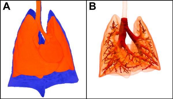
The use of anatomically accurate, animal-specific airway geometries is important for understanding and modeling the physiology of the respiratory system. One approach for acquiring detailed airway architecture is to create a bronchial cast of the conducting airways. However, typical casting procedures either do not faithfully preserve the in vivo branching angles or produce rigid casts that when removed for imaging are fragile and thus easily damaged. We address these problems by creating an in situ bronchial cast of the conducting airways in rats that can be subsequently imaged in situ using 3D micro-CT imaging. We also demonstrate that deformations in airway branch angles resulting from the casting procedure are small, and that these angle deformations can be reversed through an interactive adjustment of the segmented cast geometry. Animal work was approved by the Institutional Animal Care and Use Committee of Pacific Northwest National Laboratory.
Keywords: CT, pulmonary, bronchial cast, airways, warping
Introduction
Like other organ systems, the lung is susceptible to various diseases that can disrupt its overall structure and function. Such changes can diminish a patient’s quality of life or pre-dispose sensitive subpopulations to further complications. Computational fluid dynamics (CFD) has played a vital role in our understanding of the respiratory system in both health and disease [1]. In particular, CFD techniques have been widely used to model particle deposition and uptake of soluble gases in the respiratory system [2-8]. Historically, due to limited computational resources, researchers have used simplified and idealized two-dimensional (2D) and three-dimensional (3D) models of the tracheobronchial tree based largely on Weibel [9], Raabe et al. [10], and/or Horsfield [11], wherein all the airways in a given airway generation have identical lengths and diameters. With advances in computational techniques and the advent of in vivo 3D imaging modalities like x-ray computed tomography (CT) and magnetic resonance imaging (MRI), CFD models based on anatomically realistic 3D geometry are the current state-of-the-art in respiratory modeling [8, 12-14]. For example, Corley et al. [8] coupled imaging-based respiratory geometries of the rat, human, and monkey to physiologically-based pharmacokinetic (PBPK) models to assess uptake of acrolein along the respiratory tract. Furthermore, when using CFD to model particle deposition in the respiratory system, it is desirable to maximize the number of distal airways represented, since inhaled particles, depending on the particle size, deposit in different airway generations [15]. However, the number of distal airways captured during in vivo imaging is limited due to resolution constraints and a lack of adequate contrast; hence, lung airway casts are an attractive alternative to represent the distal tracheobronchial airways in the 3D models.
Beyond 3D representation of airways, a more detailed lung airway enables more accurate morphometry-based knowledge [15, 16]. Morphometry knowledge is important because it can provide the numerical constraints for the airway geometry, which can be applied in space-filling algorithms that extrapolate observed geometry to the entire lung. In addition, airway morphometry from multiple animals can be reduced into a small set of model parameters that inform the performance of an “average” animal and estimate the variance within a population and sub-populations, including disease models and genetic variants.
Due to the inherent characteristics of typical casting procedures, in which lungs are removed from the thorax and fixed prior to casting [17], the branching angles are different from the in vivo airways. This can be remedied by in situ casting, although such casts are typically made from silicone rubber and are easily distorted when removed from the lung [18, 19]. Alternatively, rigid casts can be made [20]; however, rigid casts are extremely fragile and prone to breakage. Although we have made in situ rigid rat lung casts in the past [8, 16], we now show a new method to reduce the geometric distortions that begins with casting the lung in situ with an easy-to-work-with silicone compound, followed by imaging the cast while it is still in the thorax. This has the additional advantage of not requiring the removal of the lung tissue from the cast. It also prevents the need to trim or destroy the cast in order to study fine details. However, in situ casting and imaging can still result in differences between the airway cast geometry as compared to an in situ air-filled lung at total lung capacity (TLC). Such differences are due to the formation of trapped air pockets exterior to the lung but within the thorax that are not expelled during casting (see Figure 1).
Figure 1.
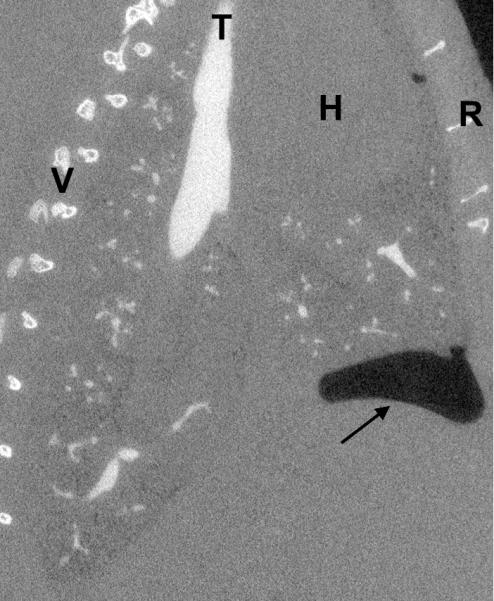
Sagittal view of a casted rat lung. The arrow indicates the location of an intrathoracic air pocket, a common artifact of the casting method, bounded by the lung, the chest wall, and the diaphragm (at the head of the arrow). V=vertebrae, T=trachea, H=heart, R=ribs.
We describe an approach for creating an image-ready in situ cast of the rat bronchial tree based on the method of Phalen et al. [18]. We demonstrate that the segmented cast image imprecisely matches the segmented airway tree of the same lung imaged at TLC prior to casting. We show how interactive deformation of a surface mesh of the lung cast can be used to match cast image to the TLC image. Our deformation technique utilizes dual quaternion skinning [21, 22], an algorithm for deforming surfaces using a control skeleton that results in natural surface deformations.
Methods
All animal work was done in accordance with a protocol approved by the Institutional Animal Care and Use Committee (IACUC) of Pacific Northwest National Laboratory. Male Sprague-Dawley rats approximately 320 g were used.
To acquire an image at TLC, rats were euthanized by CO2 asphyxiation then orally intubated with a 14 gauge catheter tube. The lungs were inflated to ~25 cmH2O and held at that pressure with a constant supply of air regulated by a water column. The lungs were imaged with micro-CT (GE eXplore CT120) using the following settings: 90 kVp, 40 mA, 16 ms exposure time, 900 projections over 360° gantry rotation, and 2×2 binning. The gantry rotates at a rate of ~0.019 radians/sec, so total imaging time was about 5.5 minutes; animal positioning and scanner set-up required an additional ~3 minutes. Images were reconstructed to 50 μm isotropic resolution using supplied software.
Following TLC imaging, an in situ cast was made of the lung airway tree following the method of Phalen et al. [18]. The trachea was exposed just below the larynx, and the catheter tube was inserted and securely tied with #2 braided silk surgical suture. The ribcage was exposed but left intact, and three slits were made on each side between ribs in the upper, middle, and lower thorax allowing the lungs to collapse. A 3-way valve was connected to the trachea tube, and the lungs were inflated to ~30 cmH2O with degassed physiological saline through one port of the valve. The lungs were held at that pressure while the casting agent was prepared. The casting agent consisted of 10 g Dow-Corning 734 flowable sealant, 3.7 g Dow-Corning 200 fluid, and 1.3 g of Ultravist (iopromide, Bayer HealthCare), an iodine-based CT contrast agent. After thorough mixing, the casting agent was degassed in a desiccation chamber using a mechanical vane pump. Once all air bubbles were removed, ~3 mL of the mixture was drawn into a 5 mL syringe. The syringe was then connected securely to the remaining valve port, and the saline port was closed off. A syringe pump (KD Scientific, model 780100) was used to inject 2.2 mL of the casting agent at a rate of 0.33 mL/min over 6.7 min. As the casting agent entered the lungs it forced the saline to migrate out through the lung tissue and be expelled through the slits in the ribcage, as described in [18, 19]. Following cast injection, the syringe was disconnected and the rat thorax was imaged again using the same imaging settings. The trachea tube (with valve attached) was left intact to avoid disturbing the cast.
Airway segmentation of the in situ cast image was performed using an automated intensity-based thresholding with connectivity validation as described by Carson et al. [23]. The airways of the TLC image were semi-automatically segmented using intensity threshold-based approaches described by Carson et al. [24] in conjunction with interactive segmentation using Digital Data Viewer (DDV) (http://cgc-code.org/). A 3D median filter was applied to the segmented TLC airway data to improve surface boundary continuity. 3D surface meshes of the TLC and cast airways were then generated using marching cubes [25] within DDV and Fiji (http://fiji.sc), respectively. Surface quality and topology validation of geometries was accomplished using Polymender [26] and Topomender [27]. To prepare the cast geometry for future CFD simulations, the surface was smoothed using volume conserving smoothing [28] and airway terminals in the cast mesh were truncated perpendicular to the centerline at a user-defined airway diameter threshold as described in [29]. Manual truncation of any missed or inappropriately chopped terminal airway was performed using Magics software by Materialise® (http://www.materialise.com/), as in Kabilan et al. [12].
Registration of the cast geometry to match the TLC airway was performed by first generating a centerline connecting each bifurcation of the cast airway using the function medax_table within BioGeom (http://simtk.org/home/biogeom), producing a file containing the coordinates of each node and associated connectivity. Next, to facilitate independent control over each airway branch and respective downstream branch elements, we added an additional node to each airway at a location 10% of the branch length below the parent node branch point and output data in fbx collada format. Then, the cast mesh, its associated skeleton, and the TLC mesh were input into Maya (http://autodesk.com/maya/). Within Maya, the cast mesh and its skeleton were bound using integrated skinning tools; Maya utilizes heat-map binding, which weights skeleton-mesh affinity based on a heat diffusion technique, and dual-quaternion skinning [21, 22], which eliminates undesirable deformation effects. Using Maya’s graphical interactive interface for manually controlling skeletons and associated surface meshes, the cast mesh was rigidly aligned with the TLC mesh via translations and whole-body rotations. As a final step, using the same Maya interface, the cast mesh was further registered to the TLC mesh by rotating and translating individual nodes.
Results
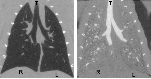
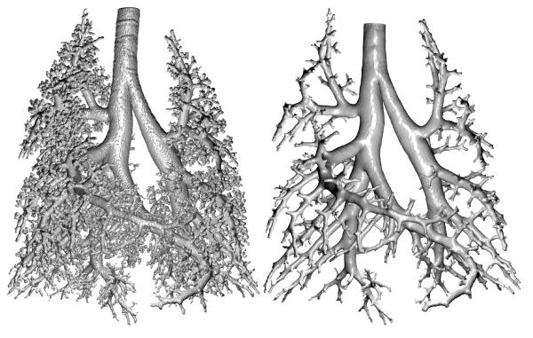
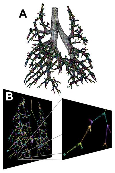
Figure 2 illustrates the appearance of CT images before and after casting. An example coronal slice of a CT image taken at TLC is displayed along with the cast image in the same rat. In the TLC image, the airways and parenchyma are dark (air-filled), while in the complementary cast image the airways are white (cast-filled) and the parenchyma grey (saline-filled). The contrast agent added to the cast material results in an x-ray opacity of the cast comparable to that of bone, which helps distinguish the cast for segmentation. The 3D surface rendering of the segmented cast is shown in Figure 3 along with the surface geometry after smoothing and outlet trimming. Figure 4A illustrates the surface geometry with its associated skeleton for controlling deformation of branches in Maya. A detail of the skeleton and branches is shown in Figure 4B.
Figure 2.
Coronal view of a rat lung at TLC before (left) and after (right) in situ casting. The airways in the before image appear dark and in the after image appear white. R=right lung, L=left lung, T=trachea.
Figure 3.
Segmented lung cast image before (left) and after outlet truncation (right). Orientation is the same as that in Figure 2.
Figure 4.
Skeleton for controlling deformation of cast. A) The skeleton with associated surface geometry for the lung cast after outlet truncation. B) The skeleton with the extra nodes (seen as circles) added for controlling branch angles.
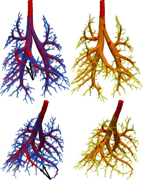
The alignment between the cast surface geometry and the TLC airway geometry prior to registration is displayed in Figure 5 in blue and red, respectively. The benefit of in situ casting and imaging is manifest by the close initial alignment between the two geometries. The greatest misalignment between airways is seen at the right middle lobe (indicated by black arrows), which was the lobe most affected by an intrathoracic air pocket (see Figure 1). Using our approach, we were able to successfully register the cast surface geometry to match the TLC surface geometry. The resulting alignment between the Maya augmented cast surface geometry in yellow and the TLC airway geometry again in red is also shown in Figure 5. Small adjustments to airway angles were sufficient to dramatically improve alignment.
Figure 5.
Alignment of the TLC airway image (red) with the segmented and truncated cast before (blue) and after (yellow) registration. The arrows indicate the airway with the greatest misalignment.
Discussion
Creating lung casts in animals as part of pulmonary studies is a powerful approach to increasing the amount of specimen-specific detail. In our lab, casting is often a final step in a long, multi-week study of pulmonary dynamics in an animal in response to an experimental challenge. Thus, the ability to properly and fully utilize cast information is important to conducting successful CFD simulations.
We have found that in situ casts can be reliably and reproducibly created using the methods described herein. The volume of cast material injected into the lungs is particularly important. Overfilling the lungs can result in intrusion of the distal airways, which obfuscates them in the cast CT image and results in a “cauliflower” appearance of the cast termini. On the other hand, underfilling does not provide a sufficient number of airways for CFD modeling, particularly after airway truncation of the segmented image. We ultimately determined the injected volume by trial and error, with the approximate airway tree volume extracted from a CT scan used as the starting point. In addition, it is critical to avoid air bubbles in the cast. Air bubbles that are suspended entirely within the cast can be easily removed at the segmentation stage; however, air bubbles can cause blockage of the airways and prevent the cast material from penetrating deeply enough. Indeed, we have observed entire lobes that were unfilled due to such blockages. Bubbles can result from inadequate degassing, but they can also be introduced from the dead space of the valve and trachea tube. To mitigate this, we recommend connecting the syringe and trachea tube to the valve while saline is flowing out in order to fully displace any air in the valve body.
The cast need not be fully cured for imaging; indeed, the cast should be imaged immediately. Extended delays can result in the lung drying out, and because the cast is not rigid, it will not support the lung tissue in its natural, in situ shape. We have not observed any changes due to drying over the course of an imaging session (which would be manifest as blurring in the image), but we have observed dramatic differences in an animal refrigerated overnight.
The placement and security of the trachea tube are important issues as well. An improperly secured tube can easily become dislodged during casting, particularly while making connections of the valve or syringe. Surgical suture is typically sufficient to hold the trachea tube in place, but a drop of super glue may be used to assure that the tube will not slip or leak. Also, careless placement of the trachea tube can result in the end residing past the carina, thereby cutting off an entire lobe from being casted.
A common casting technique utilizes negative pressure injection, in which a lung is placed in a vacuum chamber, and the cast material is drawn into the lung via negative pressure [17]. Visual contact with the lung during this technique is necessary to avoid overdistension and to maintain an appropriate pressure balance. Thus, this technique is typically done with fixed, excised lungs, because in situ lungs remain hidden within the chest cavity. In our work, preservation of the in vivo airway tree geometry is of primary importance, and removal of the lungs from the thoracic cavity results in distortion as lobes move relative to one another [18].
The addition of the contrast agent to the cast mixture facilitates segmentation of the cast. However, it also introduces two complications. The iopromide used herein is water soluble, and therefore requires thorough mixing with the silicone oil and sealant. Inadequate mixing can result in iopromide “bubbles” in the cast. The presence of very small iopromide bubbles has not caused any problems with segmentation, although large ones have introduced beam-hardening artifacts (data not shown). After data shown herein were collected, we investigated if the addition of an emulsifier would prevent this problem. Images showed that adding a small drop of household dish soap to a standard casting mixture eliminated the iopromide bubbles (data not shown). Also, we have observed that iopromide inhibits thorough curing of the cast, leaving the cast tacky or gummy, which would make it unsuitable for ex situ measurements [15]. To address this, we tried using tantalum powder as an alternative contrast agent. Results showed that particle agglomeration in the mixture resulted in worse imaging artifacts than the iopromide bubbles (data not shown).
There are several limitations of our casting approach. 1) We did not measure the pressure required to inject the casting material. The pressure is high enough to force the saline to permeate through the visceral pleura, as observed by Phalen et al. and Schreider et al. [19, 23], and high pressures may result in distortion of the lung and parenchymal damage. However, as shown in Figures 2 and 5, the cast image closely matches the pre-cast image acquired at TLC, indicating that geometrical distortions are minimal. 2) The lungs were inflated to a high pressure with saline to assure that the lungs, which were not visible within the chest cavity, were fully inflated to receive the casting compound. This is important because we have observed that the compound will not enter lung that is collapsed. As mentioned, the high inflation of the lung did not appear to distort the geometry of the airway tree. 3) Other casting compounds may provide satisfactory, or improved, results. We did not investigate a wide range of materials, although we have produced rigid casts using epoxies [8]. Generally, the epoxies are more viscous and have a shorter pot life than the silicone compound described herein, making them more difficult to work with overall. 4) Incomplete casts may result when applying this technique to disease models. We have attempted casting rat lungs in an elastase model of severe emphysema (unpublished data). Dynamic, in vivo imaging [30] revealed that the airway feeding the distal left lobe was collapsed or blocked. After casting, we found that the cast material did not enter that region of the lung, resulting in an incomplete cast.
In addressing the registration of the cast to the TLC airway, two critical elements of the approach are choice of dual quaternion skinning, and the introduction of secondary skeleton nodes near branch points to allow proper control over branch angles in Maya. We considered alternative approaches such as the use of volumetric non-rigid registration to define the function that warps every point in the cast image to the points in the TLC image. However, one drawback of the warp-based approach is that it produces a smooth registration function and thus may not properly handle the sheer between lobes. By instead using the centerline and geometry skinning, an airway branch and its downstream branches can move independently of other branches in the lung.
We have presented a novel method of imaging the cast in situ and an approach for matching the cast surface branch angles to the TLC airways. Nevertheless, we recognize there are remaining challenges. For example, the pressure required to inject the cast material is typically higher than the tracheal pressure at TLC due to the viscosity of the casting material. Therefore, due to airway compliance [31], an additional step is still needed to appropriately adjust the diameters of all the airways in the cast to match those of the TLC airway. One issue to address in the solution will be how to handle the smaller airways that are visible in the cast, but not in the TLC image. Once the cast is accurately registered to the TLC image, the stage is set for creating a breathing airway cast using a strategy similar to the approach outlined in [32]. Specifically, accurate volume-to-volume image deformation functions can be derived [33] to automatically register the TLC image with 4D CT image of the breathing lung (as illustrated in Figure 6). Acquisition of the 4D CT images over the breathing cycle is further described in detail in [30].
Figure 6.
Alignment of the rat lung at TLC and deformed-to-match cast with an image acquired at ~8 cmH2O during dynamic imaging. A) Ventral view of the rat lungs showing the difference between the TLC image (blue) and an image acquired at ~8 cmH2O during dynamic imaging (red) [30]. Deformable registration (ANTS http://www.picsl.upenn.edu/ANTS/metric.php) was used to compute a displacement vector field between the TLC image and 4D CT image from the same rat. The displacement field was used to move the TLC image – and the lung cast geometry aligned with the TLC image (see Figure 5) – into the configuration of the lower-inflation 4D CT image using the function apply_image_displacement within BioGeom (http://simtk.org/home/biogeom). B) Ventral view showing the alignment of the cast image with the ~8 cmH2O image following deformable registration. This same process of deformable registration can be repeated to move the cast surface along the 11 time points of the 4D CT sequence, thereby capturing the motion of the airway throughout the breathing cycle.
Conclusion
In situ casting and imaging is a repeatable, reliable method of visualizing the airway tree beyond that which is typically visible in in vivo CT images. Imaged casts are then readily segmented for use in CFD simulations or morphometric measurements. We demonstrated that small changes to airway branching angles introduced by the casting procedure can be corrected for by using cast-to-TLC image registration.
Acknowledgments
We thank Tao Ju of Washington University in St. Louis for his helpful discussions and T. Curry of PNNL for assistance with animal handling. This work was supported by Award Number R01HL073598 from the National Heart, Lung, and Blood Institute and by PNNL through internal Laboratory Directed Research and Development LDRD DE-AC05-76RL01830.
Footnotes
Declarations of Interest The authors have no conflicts of interst to disclose.
References
- 1.Kleinstreuer C, Zhang Z, Li Z. Modeling airflow and particle transport/deposition in pulmonary airways. Respir Physiol Neurobiol. 2008 Nov 30;163(1-3):128–38. doi: 10.1016/j.resp.2008.07.002. [DOI] [PubMed] [Google Scholar]
- 2.Longest PW, Kleinstreuer C. Computational models for simulating multicomponent aerosol evaporation in upper respiratory tract. Aerosol Sci Technol. 2005;39:124–38. [Google Scholar]
- 3.Longest PW, Tian G, Walenga RL, Hindle M. Comparing MDI and DPI aerosol deposition using in vitro experiments and a new stochastic individual path (SIP) model of the conducting airways. Pharm Res. 2012 Jun;29(6):1670–88. doi: 10.1007/s11095-012-0691-y. [DOI] [PubMed] [Google Scholar]
- 4.Longest PW, Vinchurkar S. Effects of mesh style and grid convergence on particle deposition in bifurcating airway models with comparisons to experimental data. Med Eng Phys. 2007 Apr;29(3):350–66. doi: 10.1016/j.medengphy.2006.05.012. [DOI] [PubMed] [Google Scholar]
- 5.Tian G, Longest PW. Development of a CFD boundary condition to model transient vapor absorption in the respiratory airways. J Biomech Eng. 2010 May;132(5):051003. doi: 10.1115/1.4001045. [DOI] [PubMed] [Google Scholar]
- 6.Tian G, Longest PW. Application of a new dosimetry program TAOCS to assess transient vapour absorption in the upper airways. Inhal Toxicol. 2010 Nov;22(13):1047–63. doi: 10.3109/08958378.2010.521783. [DOI] [PubMed] [Google Scholar]
- 7.Tian G, Longest PW, Su G, Hindle M. Characterization of respiratory drug delivery with enhanced condensational growth using an individual path model of the entire tracheobronchial airways. Ann Biomed Eng. 2011 Mar;39(3):1136–53. doi: 10.1007/s10439-010-0223-z. [DOI] [PMC free article] [PubMed] [Google Scholar]
- 8.Corley RA, Kabilan S, Kuprat AP, Carson JP, Minard KR, Jacob RE, Timchalk C, Glenny R, Pipavath S, Cox T, Wallis CD, Larson RF, Fanucchi MV, Postlethwait EM, Einstein DR. Comparative computational modeling of airflows and vapor dosimetry in the respiratory tracts of rat, monkey, and human. Toxicol Sci. 2012 Aug;128(2):500–16. doi: 10.1093/toxsci/kfs168. [DOI] [PMC free article] [PubMed] [Google Scholar]
- 9.Weibel ER. Morphometry of human lung. Academic Press; NewYork: 1963. [Google Scholar]
- 10.Raabe OG, Yeh HC, Schum GM, F PR. Tracheobronchial geometry: Human, dog, rat, hamster: A compilation of selected data from the project respiratory tract deposition models. 1979:LF-53. http://maeucdavisedu/wexler/lungs/LF53-Raabe/ [Google Scholar]
- 11.Horsfield K. G. C. Morphology of bronchial tree in man. J Appl Physiol. 1968;24(3):373–83. doi: 10.1152/jappl.1968.24.3.373. [DOI] [PubMed] [Google Scholar]
- 12.Kabilan S, Lin CL, Hoffman EA. Characteristics of airflow in a CT-based ovine lung: a numerical study. J Appl Physiol. 2007 Apr;102(4):1469–82. doi: 10.1152/japplphysiol.01219.2005. [DOI] [PubMed] [Google Scholar]
- 13.Lin CL, Tawhai M, McLennan G, Hoffman E. Computational fluid dynamics. IEEE Eng Med Biol Mag. 2009 May-Jun;28(3):25–33. doi: 10.1109/MEMB.2009.932480. [DOI] [PubMed] [Google Scholar]
- 14.Nowak N, Kakade PP, Annapragada AV. Computational fluid dynamics simulation of airflow and aerosol deposition in human lungs. Ann Biomed Eng. 2003 Apr;31(4):374–90. doi: 10.1114/1.1560632. [DOI] [PubMed] [Google Scholar]
- 15.Einstein DR, Neradilak B, Pollisar N, Minard KR, Wallis C, Fanucchi M, Carson JP, Kuprat AP, Kabilan S, Jacob RE, Corley RA. An automated self-similarity analysis of the pulmonary tree of the Sprague-Dawley rat. Anat Rec. 2008 Dec;291(12):1628–48. doi: 10.1002/ar.20771. [DOI] [PMC free article] [PubMed] [Google Scholar]
- 16.Neradilek MB, Polissar NL, Einstein DR, Glenny RW, Minard KR, Carson JP, Jiao X, Jacob RE, Cox TC, Postlethwait EM, Corley RA. Branch-based model for the diameters of the pulmonary airways: accounting for departures from self-consistency and registration errors. Anat Rec. 2012 Jun;295(6):1027–44. doi: 10.1002/ar.22476. [DOI] [PMC free article] [PubMed] [Google Scholar]
- 17.Perry SF, Purohit AM, Boser S, Mitchell I, Green FH. Bronchial casts of human lungs using negative pressure injection. Exp Lung Res. 2000 Jan-Feb;26(1):27–39. doi: 10.1080/019021400269943. [DOI] [PubMed] [Google Scholar]
- 18.Phalen RF. Casting Lungs in-Situ. Anat Rec. 1973;177(2):255–63. doi: 10.1002/ar.1091770207. [DOI] [PubMed] [Google Scholar]
- 19.Schreider JP, Raabe OG. Replica casts of the entire respiratory airways of experimental animals. J Environ Pathol Toxicol. 1980 Sep;4(2-3):427–35. [PubMed] [Google Scholar]
- 20.Nonaka M, Kadokura M, Tanio N, Yamamoto S, Kataoka D, Inoue K, Takaba T. Changes in lung lobar volume and bronchial deformity after right upper lobectomy. Surg Today. 1998;28(3):285–8. doi: 10.1007/s005950050122. [DOI] [PubMed] [Google Scholar]
- 21.Kavan L, Collins S, Žára J, O’Sullivan C, editors. Skinning with dual quaternions. Proceedings of the 2007 symposium on Interactive 3D graphics and games; ACM; 2007. [Google Scholar]
- 22.Kavan L, Collins S, Žára J, O’Sullivan C. Geometric skinning with approximate dual quaternion blending. ACM Transactions on Graphics. 2008;27(4):105. [Google Scholar]
- 23.Carson JP, Einstein DR, Minard KR, Fanucchi MV, Wallis CD, Corley RA. High resolution lung airway cast segmentation with proper topology suitable for computational fluid dynamic simulations. Comp Med Imag Graphics. 2010;34(7):572–8. doi: 10.1016/j.compmedimag.2010.03.001. [DOI] [PMC free article] [PubMed] [Google Scholar]
- 24.Carson JP, Kuprat AP, Jiao X, Dyedov V, del Pin F, Guccione JM, Ratcliffe MB, Einstein DR. Adaptive generation of multimaterial grids from imaging data for biomedical Lagrangian fluid–structure simulations. Biomech Model Mechanobiology. 2010;9(2):187–201. doi: 10.1007/s10237-009-0170-5. [DOI] [PMC free article] [PubMed] [Google Scholar]
- 25.Lorensen WE, Cline HE, editors. ACM Siggraph Computer Graphics. ACM; 1987. Marching cubes: A high resolution 3D surface construction algorithm. [Google Scholar]
- 26.Ju T, editor. ACM Transactions on Graphics. ACM; 2004. Robust repair of polygonal models. [Google Scholar]
- 27.Zhou QY, Ju T, Hu SM. Topology repair of solid models using skeletons. Visual Comp Graphics. 2007;13(4):675–85. doi: 10.1109/TVCG.2007.1015. [DOI] [PubMed] [Google Scholar]
- 28.Kuprat A, Khamayseh A, George D, Larkey L. Volume conserving smoothing for piecewise linear curves, surfaces, and triple lines. J Comp Phys. 2001 Sep 1;172(1):99–118. [Google Scholar]
- 29.Jiao X, Einstein DR, Dyedov V, Carson JP. Automatic identification and truncation of boundary outlets in complex imaging-derived biomedical geometries. Med Biol Eng Comput. 2009 Sep;47(9):989–99. doi: 10.1007/s11517-009-0501-9. [DOI] [PMC free article] [PubMed] [Google Scholar]
- 30.Jacob RE, Lamm WJ. Stable small animal ventilation for dynamic lung imaging to support computational fluid dynamics models. PLoS ONE. 2011;6(11):e27577. doi: 10.1371/journal.pone.0027577. [DOI] [PMC free article] [PubMed] [Google Scholar]
- 31.Sera T, Fujioka H, Yokota H, Makinouchi A, Himeno R, Schroter RC, Tanishita K. Localized compliance of small airways in excised rat lungs using microfocal X-ray computed tomography. J Appl Physiol. 2004 May;96(5):1665–73. doi: 10.1152/japplphysiol.00624.2003. [DOI] [PubMed] [Google Scholar]
- 32.Yin Y, Choi J, Hoffman EA, Tawhai MH, Lin CL. A multiscale MDCT image-based breathing lung model with time-varying regional ventilation. J Comp Phys. 2013 doi: 10.1016/j.jcp.2012.12.007. dx.doi.org/10.1016/j.jcp.2012.12.007. [DOI] [PMC free article] [PubMed] [Google Scholar]
- 33.Jacob RE, Carson JP, Thomas M, Einstein DR. Lung Hysteresis Derived from Dynamic 4D CT of Healthy and Emphysematous Rats. PLoS ONE. 2013 doi: 10.1371/journal.pone.0065874. submitted. [DOI] [PMC free article] [PubMed] [Google Scholar]


