Abstract
By genetically encoding affinity for inorganic materials into the capsid proteins of the M13 bacteriophage, the virus can act as a template for the synthesis of nanomaterial composites for use in various device applications. Herein, the M13 bacteriophage is employed to build a multifunctional and three-dimensional scaffold capable of improving both electron collection and light harvesting in dye-sensitized solar cells (DSSCs). This has been accomplished by binding gold nanoparticles (AuNPs) to the virus proteins and encapsulating the AuNP-virus complexes in TiO2 to produce a plasmon-enhanced and nanowire (NW)-based photoanode. The NW morphology exhibits an improved electron diffusion length compared to traditional nanoparticle-based DSSCs and the AuNPs increase the light absorption of the dye-molecules through the phenomenon of localized surface plasmon resonance. Consequently, we report a virus-templated and plasmon-enhanced DSSC with an efficiency of 8.46%, which is achieved through optimizing both the NW morphology and the concentration of AuNPs loaded into the solar cells. In addition, we propose a theoretical model that predicts the experimentally observed trends of plasmon-enhancement.
Keywords: M13 bacteriophage, bio-template, three-dimensional network, dye-sensitized solar cells, electron transport, light harvesting, localized surface plasmon resonance
Meeting the ever-growing need of affordable clean energy requires the development of inexpensive and environmentally friendly synthesis routes that are capable of producing efficient energy conversion devices. Using biological or polymeric materials as templates enables the assembly of hybrid materials at the nanoscale using aqueous-based and low-temperature synthesis. One particularly versatile bio-template is the M13 bacteriophage, a filamentous virus that is 880 nm in length and 6.5 nm in diameter. It has demonstrated the ability to assemble or nucleate a broad range of materials, including metals,1 semiconductors,2 polymers,3 carbon nanotubes,4 and metal oxides.4 Through genetic engineering of the surface coat proteins, the targeted materials can be assembled along the virus surface to produce functional materials with two-5 or three-dimensional (3D) morphologies for various device applications, including fuel cells,6 lithium ion batteries,7, 8 photo-catalysts,9 and photovoltaics.4, 10, 11
Dye-sensitized solar cell (DSSC) is a promising solution-processed photovoltaic technology.12 The key components of a DSSC include dye-molecules converting photons into electron-hole pairs and nanoporous titanium dioxide (TiO2) thin films (photoanodes) transporting the photo-generated electrons. The power conversion efficiency (PCE) of DSSCs is mainly determined by the ability of photoanodes to harvest light and to collect electrons.13 Generally, efficient light harvesting and electron collection requires the consideration of many design criteria, including morphologies and materials. Nanostructures of TiO2 with a high aspect ratio, such as nanorods,14 nanotubes15 and nanofibers,16 have been proven to be more efficient electron collectors than the randomly-packed nanoparticle (NP) architecture commonly used in DSSC photoanodes. However, one-dimensional (1D) structures provide less surface area for the adsorption of dye, reducing light harvesting. To achieve efficient light harvesting, the development of highly-absorbing dye-molecules or other mechanisms to increase optical absorption are required, such as light concentration with the localized surface plasmon resonance (LSPR) of noble metal NPs.17–20 Therefore, different functional materials are required for separately improving electron collection and light harvesting.
Here, we report a novel 3D viral network as a versatile platform for DSSCs which can template TiO2 nanowires (NWs) for efficient electron transport, and can also bind AuNPs to incorporate them uniformly into the photoanodes for improved light harvesting of dye-molecules via LSPR. Templated by a crosslinked virus hydrogel scaffold, the TiO2 NWs provide a direct pathway for electron transport from the photo-excited dyes to the current collector (Scheme 1) in the photoanode. The linear morphology yields an increased electron diffusion length (Ln) compared to conventional NP-based photoanodes. In addition, the M13 virus can bind AuNPs prior to the templated synthesis of TiO2; the resulting TiO2-coated AuNPs generate LSPR that improve the photo-absorption of dye-molecules adsorbed on the Au@TiO2 nanocomposites (Scheme 1). As a result, the 3D plasmon-enhanced virus-templated photoanodes exhibit efficient electron collection and improved light absorption simultaneously. An optimized amount (1.03 wt.%) of AuNPs homogeneously distributed throughout the virus-templated photoanode enhances the short-circuit current density (JSC) from 10.97 to 13.72 mA cm−2 and improves the PCE from 6.03% to 8.46%. This is further investigated theoretically by developing a numerical model that calculates the electric-field enhancement in the system. The proposed numerical model accurately captures the trend of variation of the PCE with the concentration of AuNPs.
Scheme 1.
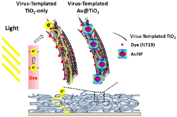
Structures and mechanisms of DSSCs with the virus-templated TiO2 and Au@TiO2 photoanodes.
RESULTS AND DISCUSSION
3D M13 Virus-Templated Photoanodes for Improved Electron Collection
To generate a 3D scaffold, a virus hydrogel network is first formed on a fluorine-doped tin oxide (FTO) using an aqueous glutaraldehyde solution as the crosslinking agent (Figure 1). Glutaraldehyde has a high reactivity with amine groups at a near-neutral pH and is able to crosslink amine groups together with thermally and chemically stable covalent bonds.21 The virus solution (specific gravity, SG~1, pH = 7.4) is dropped onto the FTO substrate in a 1 cm2 area defined by a 25-μm-thick Surlyn film spacer; the substrate is then placed upside-down on the surface of the glutaraldehyde solution (SG~1.1). As the glutaraldehyde diffuses across the fluid interface and upward into the virus solution, the amine groups on the virus coat proteins react with glutaraldehyde and stable covalent bonds between viruses are formed. After two hours of crosslinking, a virus hydrogel is spontaneously formed on the substrate.
Figure 1.

Schematic illustration of 3D porous TiO2 photoanode fabrication process, including (1) hydrogel formation, (2) TiO2 nucleation and (3) annealing.
After the virus hydrogel is achieved, the virus-templated TiO2 NWs are formed directly on the substrate by a two-step aqueous phase nucleation method using solutions of TiO2 precursors (e.g. TiCl4, (NH4)2TiF6) which sequentially deposit a conformal thin TiO2 layer on the virus template. The mechanism of the crystal growth of TiO2 crystallites by hydrolysis of TiCl4 is already well-understood.22 During the hydrolysis of TiCl4 at 50 °C (described in Equation (1)), the amorphous and anatase TiO2 nanocrystallites, observed in X-ray diffraction (XRD) pattern (Figure S1), nucleate preferentially on the surface of the virus template due to the lower interfacial energy needed for the heterogeneous nucleation.
| (1) |
A subsequent TiO2 nucleation is introduced using (NH4)2TiF6 and H3BO3 solution to reduce film cracking (imaged by scanning electron microscopy (SEM) in Figure S2); this reaction proceeds by the following mechanism described in Equation (2) and (3):
| (2) |
| (3) |
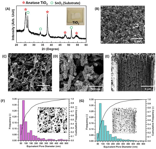
Then, the resulting virus-templated TiO2 structure is annealed at 500 °C for at least an hour, which provides enough heat and time to (1) remove the sacrificial virus scaffolds, (2) transform the amorphous/anatase nanocrystallites into anatase NPs (XRD analysis are shown in Figure 3(A)) and (3) sinter the NPs together into a percolative network.
Figure 3.
(A) XRD analysis of the annealed virus-templated anatase TiO2 photoanodes. SEM images of the virus-templated TiO2 photoanodes in (B)-(D) top-down view and (E) cross-section view. The pore size distributions calculated by the SEM images in (F) top-down view and (G) cross-section view, respectively.
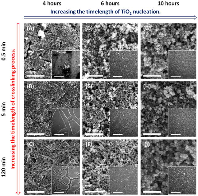
The aspect ratio of the NWs and the film quality mainly depend on the shape of crosslinked viral hydrogel and the TiO2 nucleation on the template. Therefore, three related parameters are tuned: (1) timelength of the crosslinking process, (2) timelength of the nucleation in the TiCl4 solution and (3) concentration of the TiCl4 solution. First, the crosslinking process time affects the aspect ratio of the virus-templated NW. Longer crosslinking process times result in the formation of longer and denser viral bundles, leading to the formation of higher aspect ratio NWs in the photoanodes (SEM images are shown in Figure 2(C) and 2(F)). Also, longer nucleation times in the TiCl4 solution result in the formation of more TiO2 crystallites on the viral template. The thicker TiO2 formation on the template can sustain the thermal tension experienced during the post-anneal cooling process and thus reduce film cracking. However, when the nucleation period exceeds ten hours, excessive particle nucleation leads to pore filling and random particle aggregation on the viral template (SEM images are shown in Figure 2(G)–2(I)). In addition, the concentration of the TiCl4 solution affects the TiO2 nucleation and thus the film quality. As shown in Figure S3(A) and S3(B), a lower concentration of the TiCl4 solution (0.04 M and 0.1 M) gives rise to more crack-prone NW-based films. An optimal concentration (0.2 M) of the TiCl4 solution produced a crack-free, yet interconnected virus-templated network, as shown in Figure S3(C). However, when the concentration of the TiCl4 solution is increased to 0.4 M, larger particles are nucleated on the viral template, leading to lower aspect ratio wires and a reduced surface-to-volume ratio structure (Figure S3(D)).
Figure 2.
SEM images of the annealed TiO2 photoanodes templated by virus hydrogels in different timelength of crosslinking process and fabricated in different timelength of TiO2 nucleation. The scale bar is 2 μm, and the one in the inset is 30 μm. All of the films are sequentially nucleated with (NH4)2TiF6/H3BO3 solution.
After the virus-templated thin films are fabricated at the optimized condition (two-hour crosslinking, six-hour nucleation and 0.2 M TiCl4 solution), the as-obtained nanostructure are composed of tightly packed TiO2 crystallites (~10 nm in diameter) forming interconnected porous NWs, which have been imaged by SEM in Figure 3(B) and 3(C) and transmission electron microscopy (TEM) in Figure 5(F). Compared to the size of individual viral particles, the virus-templated TiO2 NWs are approximately 150 nm in diameter and 2–3 μm in length (Figure 3(C) and 3(D)), which suggests that each NW in the photoanode is templated by a bundle of viruses. In addition, the mesoporous structure of the interconnected NW network persists throughout the 13-μm-thick film, providing directional pathways for improved electron transport (Figure 3(E)). Such a permeable matrix with interconnected pores maximizes interfacial contact with the electrolyte, thereby increasing the mobility of redox couples and minimizing back-recombination. In addition, the film porosity and the pore size distribution are investigated by analyzing the SEM images with an image analysis program (ImageJ). The porosities calculated from the top-down view (Figure 3(C)) and cross-section view (Figure 3(E)) SEM images are 51.4% and 48.0%, respectively. The porosity, which influences the overall performance by affecting the light absorption and electron diffusion, agree well with the optimal porosity reported in literatures.23 The pore size distributions (Figure 3(F) and 3(G)) are calculated from the top-down view and cross-section view SEM images as well. The equivalent pore diameter ranges from 50 nm to 500 nm and the average pore diameter is 129.2 nm and 131.0 nm in both top-down view and cross-section view SEM images, respectively. It is noteworthy that both image views give similar results for porosity, pore size distribution and average pore diameter, which indicates that the porous structure is spatially uniform.
Figure 5.
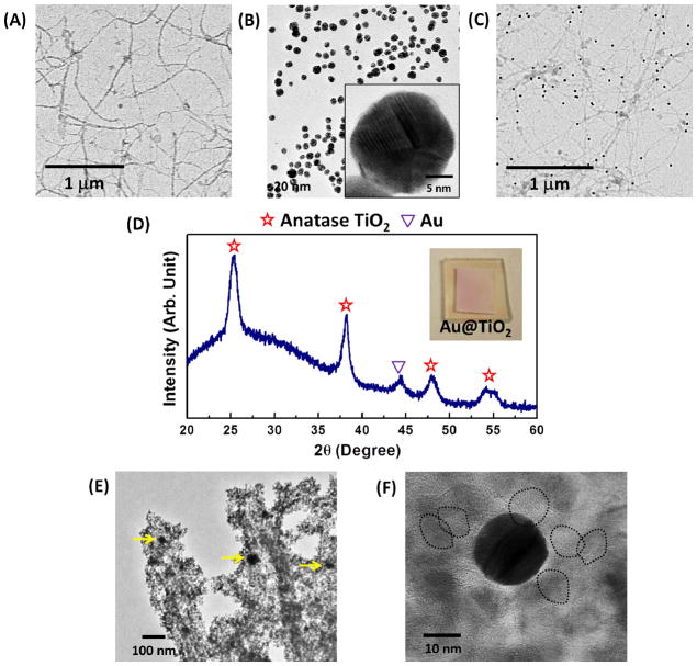
TEM images of (A) M13 virus, (B) as-synthesized 20-nm AuNPs and (C) the AuNP-virus complex. (D) XRD analysis of the virus-templated anatase Au@TiO2 photoanode. (E) TEM image of the annealed virus-templated Au@TiO2 photoanode. The yellow arrows point out the 20-nm AuNPs embedded in TiO2 crystallites. (F) High resolution TEM image of 20-nm AuNP and 10-nm TiO2 crystallites in the virus-templated Au@TiO2 photoanodes. The black dash circles the crystallized TiO2 particles in the photoanodes.
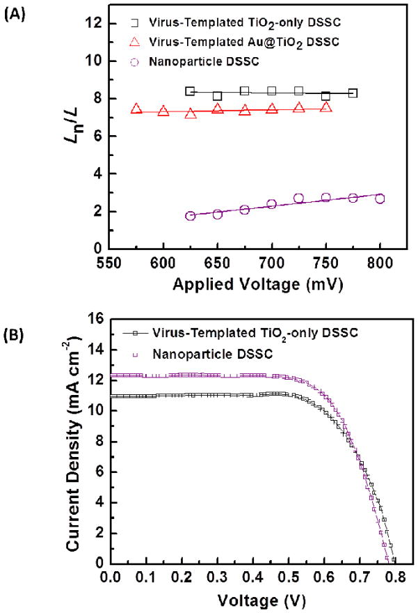
To demonstrate Ln and carrier collection of the 3D virus-templated TiO2 photoanode, the electrochemical impedance spectra (EIS) are measured after the photoanodes are assembled with the electrolyte and counter electrodes. The Ln of different DSSC photoanodes calculated from EIS are shown in Figure 4(A), and the EIS diagrams and fitting results at 625 mV are also shown in Figure S4. These results along with the corresponding efficiency of electron collection (ηCOL) are summarized in Table 1. The details of the calculation of Ln and ηCOL are provided in the Supplementary Information. As shown in Table 1, the device with the virus-templated photoanode exhibits a longer Ln (~8.4 times the film thickness) and higher ηCOL (99.6%) than the commonly used TiO2 NP-based DSSC (~1.8 times, 92.0%). These results indicate that the 3D TiO2 network composed of interconnected NWs improves electron transport by lengthening electron lifetimes and reducing opportunities for interfacial recombination.
Figure 4.
(A) Electron diffusion length analysis. Ln is the electron diffusion length and L is the photoanode thickness. (B) Device performances for DSSCs employing the virus-templated TiO2-only photoanodes. The performance of the NP-based DSSC is shown as a reference.
Table 1.
Relevant solar cell parameters obtained from the devices in Figure 4(A), 4(B) and 8(C).
| Type | Thickness (μm) | VOC (mV) | FF (%) | JSC (mA cm−2) | PCE (%) | Dye Loading (mmole cm−3) | Ln/L at 625 mV (−) | ηCOL (%) |
|---|---|---|---|---|---|---|---|---|
| Virus-Templated TiO2-only | 18.1 | 801.8 | 68.6 | 10.97 | 6.03 | 70.9 | 8.4 | 99.6 |
| Virus-Templated Au@TiO2 | 15.1 | 832.7 | 74.0 | 13.72 | 8.46 | 68.2 | 7.1 | 99.4 |
| Nanoparticle | 17.7 | 781.1 | 68.8 | 12.31 | 6.63 | 96.9 | 1.8 | 92.0 |
Furthermore, the device performance of the DSSC with virus-templated TiO2 photoanode is compared to that with a NP-based TiO2 photoanode (Figure 4(B)), and the related photovoltaic parameters: open circuit voltage (VOC), fill factor (FF), JSC, PCE and dye loading, are summarized in Table 1. The virus-templated DSSC demonstrates a PCE of 6.03% and a JSC of 10.97 mA cm−2, which are both lower than those of the TiO2 NP-based DSSC (6.63% and 12.31 mA cm−2), despite having a higher electron collection efficiency. Since the charge separation efficiency approaches unity when the N719 dye and TiO2 are used, the decreased overall performance results from the reduced surface area, dye adsorption, and thus light harvesting ability of the 1D structure of the virus-templated TiO2 NWs. In fact, the virus-templated device shows ~89.1% of JSC with only ~73.5% of the dye loading (70.9 mmole cm−3) compared to the NP-based solar cell (96.9 mmole cm−3). Therefore, the virus-templated photoanodes composed of interconnected NWs exhibit efficient electron collection, while the randomly-packed NP-based photoanode is advantageous for light harvesting. In order to compensate for the reduced dye adsorption in the virus-templated TiO2 NW structure, strategies for improving the light harvesting characteristics are designed.
M13 Virus as a Versatile Tool for Improved Light Harvesting
Localized surface plasmons (LSPs) are the elementary excited states of free electrons in metal NPs.24 Physically, these are the collective oscillations of free electrons that arise at a metal-dielectric interface when excited by light near the resonance frequency. At resonance, the electrons generate a localized near-field, which effectively concentrates light into a thin region directly around the NP. Gold and silver NPs have resonances that occur in the visible range, making them particularly useful in enhancing light harvesting in various photovoltaic technologies.25–27 The ability of M13 viruses to be programmed to bind with these noble metal NPs can thus be utilized to improve the optical absorption of the photoanodes in DSSCs. Once the viruses (TEM image in Figure 5(A)) and AuNPs (20 nm in diameter, TEM images in Figure 5(B)) are bound together through complexation in a colloidal suspension (TEM image in Figure 5(C)), the same photoanode fabrication process previously described can be performed with the AuNP-virus complexes. The morphology of the resulting virus-templated Au@TiO2 structures is similar to that of the virus-templated TiO2 films (SEM image in Figure S6). After the calcination of the virus-templated Au@TiO2 photoanode, both Au and anatase TiO2 peaks can be observed in the XRD pattern (Figure 5(D)). In addition, it is observed in the TEM images (Figure 5(E) and 5(F)) that ~10 nm TiO2 crystallites are densely packed around the ~20 nm AuNPs forming a protective shell, which prevents the AuNPs from promoting electron recombination and from being etched by the electrolyte.20
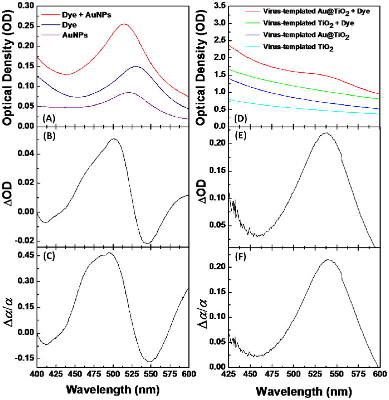
The effects of AuNPs on the optical absorption of dye-molecules in solution and in the virus-templated thin films are investigated using a UV-Vis spectrophotometer. As shown in Figure 6(A)–6(C), the light absorption of dye-molecules in an aqueous solution increases with the presence of AuNPs in the wavelength range of 450–530 nm, producing a peak absorption value that is 45% higher than the same dye-solution without AuNPs. The observation that the absorbance of the dye-AuNP mixture is also higher than a pure AuNP solution of the same concentration is attributed to the ability of the AuNPs to concentrate photons in a near-field, which are then converted into charges by neighboring dye-molecules. Similarly, the light absorption of dye-molecules in the virus-templated thin TiO2 films is increased to a maximum 21% at 540 nm (Figure 6(D)–6(F)), which is also attributed to LSPR. The shifting of the absorption peak from the AuNPs solution to a longer wavelength results from the high dielectric constant of the thin TiO2 layer surrounding the AuNPs and the surrounding porous TiO2 matrix, which has also been observed in previous reports.19, 20
Figure 6.
Plasmonic enhancement of optical absorption of dye-molecules in solution and in the virus-templated thin TiO2 film. (A) Optical absorption spectra of AuNPs, dye-molecules, and their mixture in solution, and the concentration of the components (AuNPs and dye-molecules) in all of the solutions are consistent. (B) Net changes of dye absorption (ΔOD) due to the presence of AuNPs in solution. (C) Relative changes of effective extinction coefficient of dye (Δα/α) due to the presence of AuNPs in solution. (D) Optical absorption spectra of the virus-templated TiO2 and Au@TiO2 films and their dye-adsorbed thin films (~0.6 μm). (E) ΔOD of dye due to the presence of AuNPs in thin film. (F) Relative changes of Δα/α of dye due to the presence of AuNPs in thin film. For the calculation of ΔOD and Δα/α : Δα/α = ΔOD(λ)/ODdye(λ) = (ODdye,Au(λ) – ODdye(λ) – ODAu(λ))/ODdye(λ), where ODdye(λ), ODAu(λ),and ODdye,Au(λ) are the optical densities at wavelength λ of pure dye solution, AuNP solution, and their mixture solution with the same concentrations of dye and AuNPs, respectively. For the solid-state thin films, the net absorption of dye-molecule is ODdye(λ) = ODdye,TiO2(λ) – ODTiO2(λ).
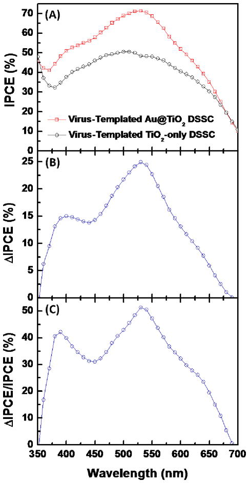
To investigate the effect of LSPs on the spectral response of the solar cells, the incident photon-to-current conversion efficiency (IPCE) of virus-templated TiO2-only and Au@TiO2 photoanodes are compared (Figure 7(A)–7(C)). The IPCE of the plasmon-enhanced DSSC is increased over the entire wavelength range compared to the TiO2-only DSSC (Figure 7(A)), indicating that the Au@TiO2 structures improve light harvesting of the dye-molecules and thus the solar cell. Moreover, the most significant enhancement is in the range of 500–600 nm with a peak around 530 nm (from 50.5% to 71.3%, Figure 7(B) and 7(C)), in agreement with the absorption enhancement of the thin films.
Figure 7.
Spectral responses of the virus-templated TiO2-only and Au@TiO2 DSSCs. (A) IPCE spectra of the DSSCs with and without the presence of AuNPs. (B) Net change of IPCE (ΔIPCE) and (C) relative changes (ΔIPCE/IPCE) due to the presence of AuNPs. ΔIPCE(λ)/IPCE = IPCEAu@TiO2(λ) – IPCETiO2-only(λ)/IPCETiO2-only(λ). IPCEAu@TiO2(λ) and IPCETiO2-only(λ) are the IPCE at wavelength λ for the virus-templated Au@TiO2 and TiO2-only DSSCs, respectively.
Device Performance of the Virus-Templated Au@TiO2 DSSC
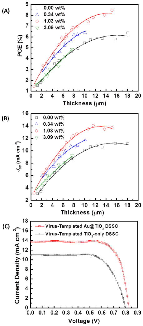
The device performance of the virus-templated Au@TiO2 photoanodes is optimized by varying the concentration of the plasmonic AuNPs and the thickness of the photoanodes (Figure 8(A) and 8(B)). The weight fraction (wt.%) of AuNPs in the TiO2 film is examined by X-ray photoelectron spectroscopy (XPS) in Figure S7. In general, thicker photoanodes tend to absorb more light, and have higher PCEs and JSC. The virus-templated Au@TiO2 DSSCs (concentrations of AuNPs, ~0.34 wt.% and ~1.03 wt.%) always show higher PCE and JSC than the virus-templated TiO2-only DSSCs with similar photoanode thicknesses. In other words, to achieve the same PCE (e.g., ~6%), the photoanode of the plasmon-enhanced DSSC (6.6 μm) is significantly thinner than that of the TiO2-only DSSC (18.1 μm), eliminating the need for 63.5% of the photoactive materials used. In addition, both PCE and JSC increase monotonically with the concentration of AuNPs from 0 to 1.03 wt.%. However, PCE and JSC decrease when the concentration of AuNPs is increased to 3.09 wt.%.
Figure 8.
Effect of LSPs on the performance of DSSCs. Dependence of (A) PCE and (B) JSC on the concentration of AuNPs in photoanodes with the different film thickness. (C) J-V curves of the most efficient virus-templated Au@TiO2 DSSC (AuNP concentration = 1.03 wt.%, PCE = 8.46%, FF = 74%, ~15.1 μm) and TiO2-only DSSC in this work.
Figure 8(C) and Table 1 show the J-V characteristics of the most efficient virus-templated plasmon-enhanced DSSC (1.03 wt.% AuNP loading) and virus-templated TiO2-only DSSC. The plasmon-enhanced DSSC achieves a JSC of 13.72 mA cm−2, a 25.1% increase compared to that of the TiO2-only DSSC, 10.97 mA cm−2. Also, the plasmon-enhanced DSSC shows higher VOC than the TiO2-only DSSC, which probably results from (1) the reduced charge recombination resulting from thinner photoanodes and (2) a lifted quasi-Fermi level resulting from the equilibrium between the quasi-Fermi level of TiO2 and the LSP energy level of AuNPs.18 As expected, the optimized thickness for the LSP-enhanced photoanode (15.1 μm) is thinner than that for the TiO2-only photoanode (18.1 μm). As a result, the virus-templated plasmon-enhanced DSSC achieves the highest PCE of 8.46%, a 40.3% increase compared to that of the virus-templated TiO2-only DSSC, 6.03%, while the photoanode thickness is decreased by 19.9%. Moreover, the AuNPs in NW-based photoanodes provides an ability to increase the light harvesting without affecting the high Ln (~7.2 times the film thickness) achieved by the virus-templated NW-based network, and thus maintain efficient ηCOL at 99.4% (Figure 4(A) and Table 1).
Computational Model of the Optimal Loading of AuNPs
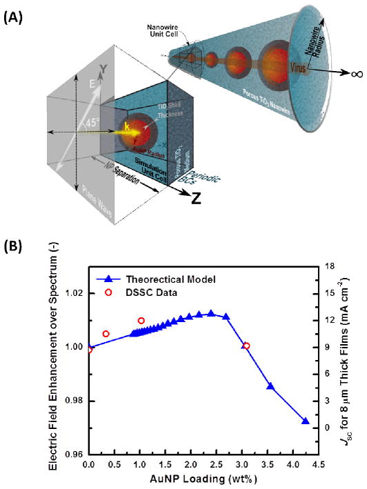
The experimental data in Figure 8(A) and 8(B) demonstrate that (1) there is an optimum AuNP wt.% that maximizes PCE and JSC and (2) the shape of the curves for PCE and JSC follow the same trend; therefore, it is reasonable to explain how AuNPs influence PCE by focusing on how they would affect JSC. At the microscopic level, the current produced in the DSSC is generated by the dye-molecules absorbing photons and converting them into electron-hole pairs. Analytically, the flux of photons striking a point in space is proportional to the electric field intensity present there. Therefore, it is expected that the short-circuit current should ultimately be proportional to the electric field intensity integrated over the volume of the device. In the absence of AuNPs, the sunlight incident on the device can be modeled as a simple plane-wave that uniformly illuminates the entire device area. However, when AuNPs are added, each particle acts as an antenna, which concentrates the sunlight within a volume several nanometers from the particle surface. Any dye-molecules that are adsorbed onto a TiO2 surface and located within the near-field of a NP will experience an enhanced electric-field, which is equivalent to being bombarded by a higher photon flux. By numerically evaluating the electromagnetic field produced by metal NPs with finite-difference time-domain (FDTD) simulations, an analytical model has been developed that quantifies the electric field enhancement due to LSPR in a DSSC, which is expected to be proportional to the short-circuit current and overall device efficiency. By modeling the virus-templated NWs as infinitely-long NWs with Au@TiO2 core-shells (CSs) embedded in a porous TiO2-electrolyte matrix (Figure 9(A)), the predicted electric-field enhancement versus AuNP loading curves follow the same trend as that empirically witnessed for JSC (Figure 9(B)). Therefore, a purely physical explanation is proposed for why an optimal AuNP loading ratio exists for maximizing PCE, which relies solely on Maxwell’s equations and reasonable modeling assumptions. Furthermore, the model predicts that light enhancement is maximized for a AuNP loading of 2.4 wt.%, which is in good agreement with the experimental data. It is worth noting that the optical response of the linear AuNP chain is dependent upon the polarization of the incident light. However, a polarization of 45° with respect to the NW axis produces the most realistic results because (1) the NWs within the device will be randomly oriented and (2) the spatial incoherence of sunlight will cause the wavetrains to arrive at the solar cell with random polarizations.
Figure 9.
(A) Schematic of the model geometry. The theoretical model idealizes the plasmon-enhanced TiO2 NWs as an infinite 1D chain of regularly-spaced Au@TiO2 CS NPs that has been encapsulated in a nanoporous TiO2 cylinder. By using periodic boundary conditions in the z-direction, the optical response of the NW can be determined through evaluating only a unit cell containing a single CS with the FDTD method. (B) The dependence of the theoretically predicted optical enhancement of the DSSC devices (left axis) and experimentally measured device JSC (right axis) on AuNP concentration. The device data plotted is for films with 8 μm film thicknesses. The modeling results are specific for a porous NW radius of 90 nm with a TiO2 volume fraction of 85%, AuNP radius of 10 nm with a 5-nm-thick solid TiO2 shell, and a plane-wave injected along the x-axis with a 45° polarization as shown in part (A).
The conceptual explanation for the trend shown in Figure 9(B) is as follows: if the particles are spaced at regular intervals far enough apart from one another (i.e. loading fraction is ~0), the electric near-field surrounding each particle does not interact with that of its neighbor. If the AuNPs are slowly brought closer to one another (i.e. the loading fraction increases), the local electric-field profile around each particle remains the same, however more AuNPs are present in the system; thus, the electric-field enhancement in the device improves with increasing loading fraction because more dye-molecules are experiencing a higher photon-flux. However, if the NPs are brought close enough together that the electric fields surrounding the individual particles interact with one another, the fields become more concentrated in the space between them. Since the NPs are modeled as having a solid TiO2 shell surrounding them (this empirically must be true, otherwise the gold surface will contact the electrolyte directly and trap charges, thereby promoting recombination), the proximity will cause the near-field to become more concentrated inside the shell itself, which is inaccessible to the dye and the electrolyte. Therefore, the photons that reside there will not contribute to current generation and higher AuNP loadings will result in a subsequent decrease in light absorption by the dye. The analysis presented here is only modeling how the AuNPs enhance the electric field intensity (or equivalently, the photon flux) experienced by the dye-molecules and no effort has been made to explain how photo-charges are generated, transported, or collected by the device. Therefore, only conclusions about the trends can be drawn when comparing the optical enhancement predictions and the JSC data shown in Figure 9(B).
CONCLUSION
In summary, the M13 bacteriophage has been successfully demonstrated as a bio-template to create a dual-functional 3D NW-based porous DSSC photoanode with efficient electron collection and improved light harvesting. The synthesized virus-templated photoanode is comprised of photoactive TiO2 NWs, which provided a direct pathway for electron collection and achieved a longer Ln than the traditional NP-based morphology. The affinity of the viral surface proteins for AuNPs enables the formation of plasmonic AuNP-virus complexes capable of improving light harvesting. We have both theoretically predicted and experimentally verified how the phenomenon of LSPR enhances the optical absorption of dye-molecules in the devices. The theoretically predicted trend of how light enhancement should vary with AuNP loading is in excellent agreement with the observed trends of PCE and JSC in the tested devices. Of the devices tested, a maximum PCE of 8.46% is observed for a AuNP loading of 1.03 wt.%. In addition to being a relatively low-cost, aqueous-based synthetic process, it is expected to be scalable to large scale production, and the device morphology is expected to be useful in other energy related applications, such as supercapacitors, lithium ion batteries and water splitting, owing to its ability to rapidly transport electrons and its potential to incorporate different functional materials into the virus-templated NW-based network via protein recognition.
MATERIALS AND METHODS
Materials
50 wt.% glutaraldehyde solution, titanium (IV) chloride (TiCl4), hydrogen tetrachloroaurate (HAuCl4), sodium citrate, acetonitrile, tert-butanol and phosphate buffered saline (PBS) buffer solution were purchased from Sigma Aldrich. Ammonium hexafluorotitanate ((NH4)2TiF6) and boric acid (H3BO3) were purchased from Alfa Aesar. Cis(diisothiocyanato)bis(2,2′-bipyridyl-4,4′-dicarboxylato)ruthenium(II) bis(tetrabutylammonium) (also named N719) and TiO2 NP paste (13/400 nm, Ti-Nanoxide D/SP) were purchased from Solaronix. N719 dye solution was prepared in acetonitrile and tert-butanol (volume ratio 1:1) mixture at 0.5 mM. All reagents were used as received and without further purification. All water was deionized (18.2 MΩ, mill-Q pore). The virus solution consisting of the E3 M13 bacteriophage (AEEE peptide expressed on the pVIII major coat protein) was diluted to 5×10¹³ phage mL−1 with PBS buffer.
Synthesis of AuNPs
The AuNP solution was prepared by the following procedure: 10 mg of HAuCl4 was initially dissolved in 100 mL of water and the solution was heated to boil. 50 mg of sodium citrate was dissolved in 5 mL of water and the solution was then added into the boiling HAuCl4 solution under vigorous stirring. The mixed solution was reacted in boiling for 30 minutes. The synthesized AuNP solution was stored at 4 °C.
Binding AuNPs on M13 Virus
The different amount of phage solution were mixed with AuNP solution and then incubated in dark condition at 4 °C for 12 hours. Then, Au-virus was precipitated through the standard polyethylene glycol and sodium chloride solution to minimize the impurities. The final pellet was redissolved and diluted to 5×10¹³ phage mL−1 with PBS buffer. The synthesized AuNP-virus solution was stored at 4 °C.
M13 Virus Hydrogel
On an FTO glass substrate, an area of 1 cm × 1 cm was defined using a 25-μm-thick Surlyn film (Solaronix Meltonix 1170-25), which was attached onto the FTO substrate by melting at 120°C for 15 minutes. 10 μl of virus solution or Au-virus solution was then dropped on the FTO. The FTO with the virus solution was inverted and put on top of a solution of 50% glutaraldehyde, which served as a crosslinking agent. The crosslinking reaction was allowed to proceed for 2 hours. Afterwards, the resulting virus hydrogels (along with the FTO substrate) were removed from the crosslinking solution and transferred to a PBS buffer to remove excess glutaraldehyde in the hydrogel overnight.
TiO2 Photoanode Generation
The crosslinked phage hydrogels were immersed in a 0.2 M TiCl4 solution for ~6 hours and in a mixture of 30 mM (NH4)2TiF6 and H3BO3 for 4 hours at 50 °C subsequently for TiO2 nucleation. After nucleation, the films were rinsed with water and then annealed at 500 °C for 30 minutes. Thicker films were achieved by repeating the fabrication process (crosslinking, nucleation and calcination). For the NP-based photoanodes, layers of commercial TiO2 NP paste were doctor-bladed on the substrates, and then annealed at 500 C for 15 minutes. Film thickness was monitored using a surface profilometer (Veeco Dektak). SEM images of the film morphology were obtained using Helios Nanolab 600 Dual Beam Focused Ion Beam System. TEM observations of synthesized nanostructures were performed using JEOL 200CX TEM with an accelerating voltage of 120 kV and JEOL 2010 TEM with an accelerating voltage of 200 kV. The optical absorption spectroscopy measurements were performed using a Beckman Coulter DU800 UV-Vis spectrophotometer. XPS measurement with a scanning monochromated Al source (spot size, 200 μm) determined the composition of the film. A depth profiling analysis was performed, sputtering with an argon source for 740 minutes, or approximately 1.5 μm in depth.
Fabrication of DSSCs
After calcination, the photoanodes were cooled to 80 °C and immersed in the N719 solution, and kept at room temperature over 24 hours. The counter-electrode was a 100-nm-thick platinum film sputtered on a FTO substrate. The electrolyte employed was a solution of 0.6 M 1-butyl-3-methylimidazolium iodide (Sigma Aldrich), 0.03 M I2 (Sigma Aldrich), 0.10 M guanidinium thiocyanate (Sigma Aldrich) and 0.5 M 4-tert-butyl pyridine (Sigma Aldrich) in a mixture of acetonitrile and valeronitrile (volume ratio, 85:15).28 The dyed TiO2 photoanodes and platinum counter-electrodes were assembled into a sandwich-type cell and sealed with a hot-melt 25 μm Surlyn. The final photoanode had dimensions of ~0.16 cm2 (4 mm × 4 mm), further determined from a calibrated digital camera image.
Characterization of DSSCs
Photovoltaic measurements were performed using an AM 1.5 solar simulator (Photo Emission Tech.). The power of the simulated light was calibrated to 100 mW cm−2 by using a reference silicon photodiode with a power meter (1835-C, Newport) and a reference silicon solar cell to reduce the mismatch between the simulated light and AM 1.5. J-V curves were obtained by applying an external bias to the cell and measuring the generated photocurrent with a Keithley model 2400 digital source meter. The voltage step and delay time of photocurrent were 10 mV and 40 ms, respectively. The dye loading of the photoanode was determined by eluting the N719 dye from the TiO2 electrode into a known amount of 0.1 M NaOH and using a UV-Vis calibration curve to determine the concentration of dye in solution to total amount of dye per film volume. IPCE spectra were obtained with a computer-controlled system (Model QEX7, PV Measurements, Inc.) consisting of 150 W xenon lamp light source and a monochromator with two 1200 g/mm diffraction gratings. The monochromator was incremented through the wavelength range from 350 nm to 900 nm to generate the spectral response of IPCE with a spectral resolution of 10 nm. The incident photon flux was determined using a calibrated silicon photodiode (calibrated by PV Measurements, Inc.). Measurements were performed in a short-circuit condition, while the cell was under background illumination from a bias light of 50 mW cm−2. Bias illumination was from the same direction as the monochromatic light, which was from the FTO side. The monochromatic beam was chopped using a computer-controlled shutter at a frequency of 4 Hz, and averaging of up to 40 shutter cycles was employed. EIS of DSSCs were measured using a Solartron 1260 frequency response analyzer. The obtained impedance spectra were fit to the transmission line model with Z-view software (v3.2b, Scribner Associates).29 The spectra were measured at various forward bias voltages (from 0.85 to 0.45 V) in the frequency range ~0.1 Hz to ~1 MHz with oscillation potential amplitudes of 10 mV at room temperature. The photoanode was connected to the working electrode. The platinum electrode was connected to the auxiliary electrode and reference electrodes. The impedance measurements were carried out at forward bias in dark conditions.
Theoretical Modeling
The optical properties of the DSSC system was theoretically investigated using the FDTD method with the software Lumerical FDTD Solutions Version 8.0.0. The plasmon-enhanced TiO2 NW morphology of the DSSC was modeled as an infinitely-long nanoporous TiO2 NW with a radius of 90 nm, which encapsulated a periodic 1D chain of AuNP-TiO2 CSs, as shown in Figure 9(A). Placing periodic boundary conditions along the z-direction allowed the simulation volume to be dramatically reduced to a unit-cell containing a single 20 nm diameter AuNP with a 5 nm thick, solid TiO2 shell. The medium surrounding the CS NP was modeled as a nanoporous TiO2/water matrix with an effective index of 2.148, which was calculated for a TiO2 volumetric fill fraction of 85% (based on TEM images) using effective medium theory.30 It was inherently assumed here that the dye-molecules would be able to infiltrate into all the pores of the TiO2 NW and thus be uniformly distributed across the volume. Multiple simulations were performed with center-to-center NP separation periods ranging from 20 to 100 nm. Each unit-cell simulation domain was illuminated by a plane-wave with a polarization oriented 45° to the NW axis at 400 different wavelengths between 350 and 900 nm. A fourth order polynomial was fitted over this wavelength range to the measured dielectric data of gold as reported by Palik.31 The refractive index of solid TiO2 was approximated as 2.34 and taken to be constant over the wavelengths of interest. This value was found by averaging the dispersion relation reported by Kim32 between the wavelengths of 350 and 950 nm.
For each simulation geometry, an enhancement factor was calculated that compares the amount of light intensity available for absorption by the dye-molecules distributed throughout the TiO2 NW matrix with and without the AuNP-TiO2 CS NPs:
where E is the electric field for the model with the AuNP-TiO2 CSs, E0 is the electric field of the incident plane wave, and the “Volume of NW Unit Cell” refers to a cylindrical slice through the porous TiO2 NW that is centered about a single AuNP-TiO2 CS with a width equal to the NP separation distance (Figure 9(A)). It is worth emphasizing that the enhancement factor is defined to calculate the overall light enhancement that the dye-molecules loaded into the porous TiO2 NW experience because the dye is what ultimately generates charges in the system. Therefore, the electric-field located within the solid TiO2 shell and the inside the AuNP core do not contribute to the above volume integral because that space is inaccessible to the dye.
The weight fraction of AuNPs in the DSSC system is defined as:
where MAuNPs is the mass of the AuNPs in the system and MTiO2 is the total mass of the TiO2 in the system, which includes the material in the thin solid shell surrounding the AuNP as well as the material in the porous TiO2/water matrix that makes up the NW volume.
Supplementary Material
Acknowledgments
This work was supported by Eni, S.p.A (Italy) through the MIT Energy Initiative Program. N.F. acknowledges support by NSF (ECCS Award No. 1028568) and by the Air Force Office of Scientific Research (AFOSR MURI Award No. FA9550-12-1-0488). M.T.K. acknowledges support from the MIT Energy Initiative Eni-MIT Energy Fellowship. P.-Y.C., X.D., F.J.B., P.T.H., and A.M.B. conceived the idea and designed the experiments. P.-Y.C. performed the synthesis and SEM imaging. P.-Y.C. and J.Q. performed the TEM imaging. P.-Y.C., X.D. and J.Q. performed the fabrication and characterization of the solar cells. M.T.K. and N.F. performed the numerical modeling study. N.-M.D.C. performed the XPS measurement. P.-Y.C., X.D., M.T.K., P.T.H. and A.M.B. co-wrote the paper and all authors discussed the results and commented on the manuscript. The authors wish to dedicate this paper to the memory of Officer Sean Collier, for his caring service to the MIT community and for his sacrifice.
Footnotes
SUPPORTING INFORMATION AVAILABLE
SEM images of the virus-templated photoanodes with/without TiO2 nucleation by (NH4)2TiF6/H3BO3 solution, SEM images of the virus-templated photoanodes nucleated in different concentration of TiCl4 solution, XRD analysis of TiO2 nanocrystallites after the hydrolysis of TiCl4, calculation of electron diffusion length and electron collection efficiency, SEM image of the Au@TiO2 virus-templated film, XPS measurement of the Au@TiO2 virus-templated film and details about the theoretical modeling study are provided in the Supporting Information. This material is available free of charge via the Internet at http://pubs.acs.org.
REFERENCES AND NOTE
- 1.Huang Y, Chiang CY, Lee SK, Gao Y, Hu EL, Yoreo JD, Belcher AM. Programmable Assembly of Nanoarchitectures Using Genetically Engineered Viruses. Nano Lett. 2005;5:1429–1434. doi: 10.1021/nl050795d. [DOI] [PubMed] [Google Scholar]
- 2.Whaley SR, English DS, Hu EL, Barbara PF, Belcher AM. Selection of Peptides with Semiconductor Binding Specificity for Directed Nanocrystal Assembly. Nature. 2000;405:665–668. doi: 10.1038/35015043. [DOI] [PubMed] [Google Scholar]
- 3.Arter JA, Taggart DK, McIntire TM, Penner RM, Weiss GA. Virus-PEDOT Nanowires for Biosensing. Nano Lett. 2010;10:4858–4862. doi: 10.1021/nl1025826. [DOI] [PMC free article] [PubMed] [Google Scholar]
- 4.Dang X, Yi H, Ham MH, Qi J, Yun DS, Ladewski R, Strano MS, Hammond PT, Belcher AM. Virus-Templated Self-Assembled Single-Walled Carbon Nanotubes for Highly Efficient Electron Collection in Photovoltaic Devices. Nat Nanotechnol. 2011;6:377–384. doi: 10.1038/nnano.2011.50. [DOI] [PubMed] [Google Scholar]
- 5.Chung WJ, Oh JW, Kwak K, Lee BY, Meyer J, Wang E, Hexemer A, Lee SW. Biomimetic Self-Templating Supramolecular Structures. Nature. 2011;478:364–368. doi: 10.1038/nature10513. [DOI] [PubMed] [Google Scholar]
- 6.Neltner B, Peddie B, Xu A, Doenlen W, Durand K, Yun DS, Speakman S, Peterson A, Belcher A. Production of Hydrogen Using Nanocrystalline Protein-Templated Catalysts on M13 Phage. ACS Nano. 2010;4:3227–3235. doi: 10.1021/nn100346h. [DOI] [PubMed] [Google Scholar]
- 7.Liu Y, Zhang W, Zhu Y, Luo Y, Xu Y, Brown A, Culver JN, Lundgren CA, Xu K, Wang Y, Wang C. Architecturing Hierarchical Function Layers on Self-Assembled Viral Templates as 3D Nano-Array Electrodes for Integrated Li-Ion Microbatteries. Nano Letters. 2012;13:293–300. doi: 10.1021/nl304104q. [DOI] [PubMed] [Google Scholar]
- 8.Lee YJ, Yi H, Kim WJ, Kang K, Yun DS, Strano MS, Ceder G, Belcher AM. Fabricating Genetically Engineered High-Power Lithium-Ion Batteries Using Multiple Virus Genes. Science. 2009;324:1051–1055. doi: 10.1126/science.1171541. [DOI] [PubMed] [Google Scholar]
- 9.Nuraje N, Dang X, Qi J, Allen MA, Lei Y, Belcher AM. Biotemplated Synthesis of Perovskite Nanomaterials for Solar Energy Conversion. Adv Mater. 2012;24:2885–2889. doi: 10.1002/adma.201200114. [DOI] [PubMed] [Google Scholar]
- 10.Chen PY, Ladewski R, Miller R, Dang X, Qi J, Liau F, Belcher AM, Hammond PT. Layer-by-Layer Assembled Porous Photoanodes for Efficient Electron Collection in Dye-Sensitized Solar Cells. J Mater Chem A. 2013;1:2217–2224. [Google Scholar]
- 11.Lee YM, Kim YH, Lee JH, Park JH, Park NG, Choe WS, Ko MJ, Yoo PJ. Highly Interconnected Porous Electrodes for Dye-Sensitized Solar Cells Using Viruses as a Sacrificial Template. Adv Funct Mater. 2011;21:1160–1167. [Google Scholar]
- 12.Yella A, Lee HW, Tsao HN, Yi C, Chandiran AK, Nazeeruddin MK, Diau EWG, Yeh CY, Zakeeruddin SM, Grätzel M. Porphyrin-Sensitized Solar Cells with Cobalt (II/III)-Based Redox Electrolyte Exceed 12 Percent Efficiency. Science. 2012;334:629–634. doi: 10.1126/science.1209688. [DOI] [PubMed] [Google Scholar]
- 13.Hagfeldt A, Boschloo G, Sun L, Kloo L, Pettersson H. Dye-Sensitized Solar Cells. Chem Rev. 2010;110:6595–6663. doi: 10.1021/cr900356p. [DOI] [PubMed] [Google Scholar]
- 14.Kang SH, Choi SH, Kang MS, Kim JY, Kim HS, Hyeon T, Sung YE. Nanorod-Based Dye-Sensitized Solar Cells with Improved Charge Collection Efficiency. Adv Mater. 2008;20:54–58. [Google Scholar]
- 15.Zheng Q, Kang H, Yun J, Lee J, Park JH, Baik S. Hierarchical Construction of Self-Standing Anodized Titania Nanotube Arrays and Nanoparticles for Efficient and Cost-Effective Front-Illuminated Dye-Sensitized Solar Cells. ACS Nano. 2011;5:5088–5093. doi: 10.1021/nn201169u. [DOI] [PubMed] [Google Scholar]
- 16.Kunal M, Tai-Hou T, Rajan J, Seeram R. Electron Transport in Electrospun TiO2 Nanofiber Dye-Sensitized Solar Cells. Appl Phys Lett. 2009;95:012101. [Google Scholar]
- 17.Brown MD, Suteewong T, Kumar RSS, D’lnnocenzo V, Petrozza A, Lee MM, Wiesner U, Snaith HJ. Plasmonic Dye-Sensitized Solar Cells Using Core-Shell Metal-Insulator Nanoparticles. Nano Lett. 2010;11:438–445. doi: 10.1021/nl1031106. [DOI] [PubMed] [Google Scholar]
- 18.Choi H, Chen WT, Kamat PV. Know Thy Nano Neighbor. Plasmonic versus Electron Charging Effects of Metal Nanoparticles in Dye-Sensitized Solar Cells. ACS Nano. 2012;6:4418–4427. doi: 10.1021/nn301137r. [DOI] [PubMed] [Google Scholar]
- 19.Dang X, Qi J, Klug MT, Chen PY, Yun DS, Fang NX, Hammond PT, Belcher AM. Tunable Localized Surface Plasmon-Enabled Broadband Light-Harvesting Enhancement for High-Efficiency Panchromatic Dye-Sensitized Solar Cells. Nano Lett. 2013;13:637–642. doi: 10.1021/nl3043823. [DOI] [PMC free article] [PubMed] [Google Scholar]
- 20.Qi J, Dang X, Hammond PT, Belcher AM. Highly Efficient Plasmon-Enhanced Dye-Sensitized Solar Cells through Metal@Oxide Core-Shell Nanostructure. ACS Nano. 2011;5:7108–7116. doi: 10.1021/nn201808g. [DOI] [PubMed] [Google Scholar]
- 21.Migneault I, Dartiguenave C, Bertrand MJ, Waldron KC. Glutaraldehyde: Behavior in Aqueous Solution, Reaction with Proteins, and Application to Enzyme Crosslinking. BioTechniques. 2004;37:790–802. doi: 10.2144/04375RV01. [DOI] [PubMed] [Google Scholar]
- 22.Zhang Q, Gao L, Guo J. Effects of Calcination on the Photocatalytic Properties of Nanosized TiO2 Powders Prepared by TiCl4 Hydrolysis. Appl Catal, B. 2000;26:207–215. [Google Scholar]
- 23.Ni M, Leung MKH, Leung DYC, Sumathy K. An Analytical Study of the Porosity Effect on Dye-Sensitized Solar Cell Performance. Sol Energy Mater Sol Cells. 2006;90:1331–1344. [Google Scholar]
- 24.Hutter E, Fendler JH. Exploitation of Localized Surface Plasmon Resonance. Adv Mater. 2004;16:1685–1706. [Google Scholar]
- 25.Atwater HA, Polman A. Plasmonics for Improved Photovoltaic Devices. Nat Mater. 2010;9:205–213. doi: 10.1038/nmat2629. [DOI] [PubMed] [Google Scholar]
- 26.Schuller JA, Barnard ES, Cai W, Jun YC, White JS, Brongersma ML. Plasmonics for Extreme Light Concentration and Manipulation. Nat Mater. 2010;9:193–204. doi: 10.1038/nmat2630. [DOI] [PubMed] [Google Scholar]
- 27.Wu JL, Chen FC, Hsiao YS, Chien FC, Chen P, Kuo CH, Huang MH, Hsu CS. Surface Plasmonic Effects of Metallic Nanoparticles on the Performance of Polymer Bulk Heterojunction Solar Cells. ACS Nano. 2011;5:959–967. doi: 10.1021/nn102295p. [DOI] [PubMed] [Google Scholar]
- 28.Ito S, Murakami TN, Comte P, Liska P, Grätzel C, Nazeeruddin MK, Grätzel M. Fabrication of Thin Film Dye Sensitized Solar Cells with Solar to Electric Power Conversion Efficiency Over 10% Thin Solid Films. 2008;516:4613–4619. [Google Scholar]
- 29.Halme J, Vahermaa P, Miettunen K, Lund P. Device Physics of Dye Solar Cells. Adv Mater. 2010;22:E210–E234. doi: 10.1002/adma.201000726. [DOI] [PubMed] [Google Scholar]
- 30.Bohren CF, Huffman DR. Absorption and Scattering of Light by Small Particles. Wiley-Interscience; New York: 1998. [Google Scholar]
- 31.Palik ED. Handbook of Optical Constants of Solids. Elsevier; 1998. [Google Scholar]
- 32.Kim SY. Simultaneous Determination of Refractive Index, Extinction Coefficient, and Void Distribution of Titanium Dioxide Thin Film by Optical Methods. Appl Opt. 1996;35:6703–6707. doi: 10.1364/AO.35.006703. [DOI] [PubMed] [Google Scholar]
Associated Data
This section collects any data citations, data availability statements, or supplementary materials included in this article.


