

Abstract
Nerve guidance conduits (NGCs) are FDA-approved devices used to bridge gaps across severed nerve cables and help direct axons sprouting from the proximal end toward the distal stump. In this paper we present the development of a novel electrically conductive, biodegradable NGC made from a polypyrrole-block-polycaprolactone (PPy-PCL) copolymer material laminated with poly(lactic-co-glycolic acid) (PLGA). The PPy-PCL has a bulk conductivity ranging 10–20 S/cm and loses 40 wt% after 7 months under physiologic conditions. Dorsal root ganglia (DRG) grown on flat PPy-PCL/PLGA material exposed to direct current electric fields (EF) of 100 mV/cm for 2 h increased axon growth by 13% (± 2%) towards either electrode of a 2-electrode setup, compared to control grown on identical substrates without EF exposure. Alternating current increased axon growth by 21% (± 3%) without an observable directional preference, compared to the same control group. The results from this study demonstrate PLGA-coated PPy-PCL is a unique biodegradable material that can deliver substrate EF stimulation to improve axon growth for peripheral nerve repair.
Keywords: degradeable polypyrrole, nerve conduit, electric field, cell stimulation, nerve regeneration
INTRODUCTION
Traditional treatment of large peripheral nerve injury defects involves interposition of an autologous nerve graft between the proximal and distal ends, however donor site morbidity and incomplete recovery have pushed research toward the development of nerve guidance conduits (NGC).1–3 Conduits direct growth of sprouting axons from the proximal stump, confine secreted growth and neurotrophic factors, and minimize scar tissue infiltration. NGCs fabricated from natural and synthetic materials have achieved some degree of success but nerve regrowth is slow4, thus introducing additional growth cues, such as electric field stimulation (ES), may be key to improving nerve regeneration.
Accelerating the re-innervation of tissue is considered the single most important factor in nerve repair5, where galvanotropism and galvanotaxis (directing cellular growth and migration using an electric field (EF)) are promising modalities for manipulating cell behavior because of their essential roles in tissue development and wound healing.6–12 These endogenous EFs are created from the natural separation and movement of charged biochemicals in the extracellular environment. Numerous groups have demonstrated that using an external device to apply EFs in vitro stimulated the growth and differentiation of anchorage dependent cells such as neurons, fibroblasts and epithelium cells.13–19 Similarly, works by Quigley et al. and Durgam et al. demonstrate electrically conductive polypyrrole (PPy) substrates formed into NGCs were able to stimulate the growth of neuron-like PC12 cells and dorsal root ganglia (DRG) in vitro.20,21 Stimulation of the PPy conduits using alternating/direct currents in the 100 mV range (~1 mA) for 2–8 h suggest that producing an EF across a substrate may accelerate the healing of injured nerves, possibly through increased protein adsorption to conduit surface18, polarized cellular growth22, or change in cell signaling pathways11.
Although ES is an accepted therapy in various clinical applications including deep brain stimulation and electrosurgery, there are no established protocols in using EF on peripheral nerve injury (PNI) repair. Several groups have attempted ES on animals and humans using looped wires, cuffs, or needles as electrodes to deliver various stimulation patterns through tissue23–29 where in vivo ES of peripheral nerves are beneficial overall. Drawbacks to these methods include invasive non-biodegradable metallic electrodes and direct current (DC) stimulators that are not easily approved by the FDA because of the risk of Faradaic accumulations and failures.
In this work we present the fabrication of mechanically strong and suturable NGCs that are biocompatible, biodegradable, and have sufficient conductivity to deliver ES to cells without the problems associated with metallic conductors. The novel NGCs are made an inner layer of the polypyrrole-co-polycaprolactone copolymer (PPy-PCL) that is both electrically conducting and biodegradable, and with an outer layer of poly(lactic-co-glycolic acid) (PLGA) for improved mechanical support. PPy was chosen because of its historic use as a biocompatible polymer30–32, and its production, modification, and structural arrangement can be easily controlled. PLGA and PCL were chosen for their mechanical characteristics and inherent biodegradability through hydrolysis. Cell growth and differentiation on the device with and without ES was evaluated under various in vitro conditions and electrical parameters.
MATERIALS AND METHODS
NGC fabrication of PPy-PCL with PLGA coating
Synthesis of Polycaprolactone2000diPyrrole
PCL diols (Capa® 2205 and 2200P) having average molecular weight of 2000 Dalton were obtained from Perstorp, Sweden. Pyrrole was freshly distilled prior to each use. All other chemicals were purchased from Sigma-Aldrich (St. Louis, MO) and used as received.
PCL (27.8 g, 13.9 mmol, 1 eq) was purged with argon in a flask equipped with an addition funnel for 10 min then dissolved in 100 ml of anhydrous tetrahydrofuran (THF). The clear solution was cooled with an isopropanol/liquid nitrogen bath, and then butyl lithium (2.5 M, 10 ml, 0.025 mol, 1.8 eq) was added drop-wise. The reaction was allowed to stir for a few minutes before the bath was removed, then stirred for an additional 20 min. A solution of 2-(trichloroacetyl)pyrrole (5.9 g, 0.028 mol, 2 eq) in 30 ml of anhydrous THF was transferred to the addition funnel. The lithiated-Capa was re-cooled with the bath, then trichloloacetyl-pyrrole was added drop-wise to the reaction flask. The bath was removed upon the completion of the addition and the flask was stirred for 1 h at room temperature. The reaction was quenched with a cold 1 M HCl solution until the pH was lowered to 7. The THF was removed under vacuum and the organic residue was extracted into dichloromethane with two washings. The combined extracts were washed with 5% NaHCO3 (3x), then with DI water until achieving a pH 7 (2x). The organic layer was dried over anhydrous MgSO4 and the solvent was removed under vacuum. The product was isolated with 84% yield (25.5 g). 1H NMR analysis of the product confirmed the formation of the desired product.
Copolymerization with PTS doping
Iron (III) p-toluenesulfonate (Fe[PTS]3, 15.78 g, 0.025 mol) and acetonitrile (200 ml) were placed into a 1 L round bottom flask equipped with an overhead stirrer and allowed to mix for several minutes. Pyrrole (0.8 g, 0.01 mol) and Polycaprolactone2000diPyrrole (1.6 g, 0.0007 mol) in acetonitrile (200 ml) were added to the reaction flask. The beaker used to add the monomers was rinsed with the remainder of acetonitrile (100ml) and also added to the reaction flask. The copolymerization mixture was stirred at room temp for 2 d, during which time the conducting copolymer aggregates and flocculates to form a black particulate suspension. The reaction product was centrifuged at 5000 rpm for 25 min. The supernatant was removed and the bottom layer, a black gel, was washed with mixed alcohols and centrifuged an additional three times. The PPy-PCL copolymer gel had a solid content of 9.8 wt% and the yield of dry copolymer was 63.6%.
Dispersion in nitromethane
Washed and decanted PPy-PCL was dispersed in nitromethane with a Cole-Parmer 500 W ultrasonic piezo horn immersed into the dispersion 1 cm below the surface. The horn amplitude was set to 40%, processed for 30 s, and repeated twice more with recapping and shaking between each sonication step. Samples were filtered by gravity through loosely packed glass wool to remove any remaining large particles. The dispersion looked homogenous and was stable against settling for several hours (settling occurs over a period of days). Thin films of the nitromethane dispersion were prepared by spin casting with a Chemat Technology KW-4A model spin coater (Northridge, CA) equipped with a 2.5 cm diameter vacuum chuck. Spin-cast thin films were observed to qualitatively assess film morphology and particle size.
Creating seamless NGC conduits
A freshly sonicated and filtered dispersion of PPy-PCL in 0.5 wt% nitromethane was used to coat a polished stainless steel mandrel (1.0 or 6.0 mm diam. wire, McMaster Carr, Atlanta, GA) with multiple thin layers along an 8 cm length of the mandrel, as shown in Figure 1. The polymer was spray-coated with a fine-art airbrush (15 PSI compressed air) while spinning the mandrel at 300 rpm. The amount of polymer deposited on the spinning mandrel was controlled by the volume of dispersion sprayed, typically 0.5 ml per cm length of mandrel. After the copolymer coating was air dried, a 6 wt% nitromethane solution of PLGA (85% lactic acid, 15% glycolic acid, MW = 50,000–70,000 Dalton) was airbrushed on top of the PPy-PCL layer at 0.25 ml per cm of mandrel and dried overnight at 35°C. This final NGC made of PPy-PCL/PLGA material is a non-gelled, polymeric, amorphous material.
Figure 1.

Seamless PLGA-coated PPy-PCL conduits are fabricated in five steps: (a) Bare polished stainless steel mandrel (1 mm), (b) mandrel spray-coated with PPy-PCL, (c) mandrel and PPy-PCL spray-coated with PLGA, (d) coated, dried mandrel pressed and rolled between glass plates to release tubular material, and (e) concentric tubes of PPy-PCL (core) and PLGA (shell) are trimmed to a finished product.
The ends of the tubes were trimmed to the desired length, and the conduits were pressed and rolled between two glass plates. This rolling process gently compresses the conducting polymer layer, giving it better integrity and conductivity. The rolling also causes the tube to expand 0.1 mm in diameter and detach from the mandrel as a free-standing NGC. Clinically relevant sized tubes 1.1 mm in diameter and 12 mm in length were thus fabricated. However for cell experiments, 6 mm diameter conduits were cut longitudinally to create flat film strips 5 mm in width and 12 mm in length. All cells were cultured on the inner PPy-PCL layer.
Bulk PPy-PCL and NGC conductivity
The PPy-PCL copolymer gel (without PLGA) was dried, ground, and pressed into a pellet with an infrared pellet press at 7000 psi. Each pellet was approximately 12 mm in diameter, 1.2 mm in thickness, and weighed 0.23 g. The DC bulk conductivity was measured with a Jandel 4-point probe (Linslade, Bedfordshire, UK) using standard Van der Pauw techniques.
To measure NGC conductive stability under physiological conditions, PPy-PCL/PLGA strips were submerged in phosphate buffered saline (PBS) with the ends attached to dry electrodes. A multipotentiostat (CH1040A Multipotentiostat, CH Instruments, Austin, TX) supplying 1–100 μA across the submerged strips recorded change in resistance after 20 min of stimulation.
PPy-PCL degradation
Pristine PPy-PCL copolymer pellets, as described above, were immersed in buffer solutions at pH 4.15, 7.3 and 9.0 (acetic acid, Tris, and sodium carbonate buffers, respectively). Each pellet was placed in a perforated plastic casing and submerged in buffer, agitated on an orbital shaker under 120 rpm at 37°C. The pellets were periodically removed, rinsed with DI water, air dried, weighed, and re-immersed in fresh buffer solution. Five pellets were used to determine the average percent weight loss at each time point. FT-IR spectra of the starting pristine PPy-PCL copolymer and the remaining fragmented pellets from the hydrolysis experiments were recorded in KBr pellets with a Nicolet FTIR Spectrometer (Thermo Fisher Scientific Inc., Waltham, MA).
Cell culture
Rat pheochromocytoma PC12 cells (ATCC, Manassas, VA) were used to determine ES parameters and NGC cytotoxicity. The PC12 cell line derived from the rat adrenal medulla were differentiated into a neuronal-like phenotype with neurites by exposing to nerve growth factor (NGF 2.5s, Promega, Madison, WI). Cells were grown on 100 mm tissue culture plastic dishes coated with 0.35 μg/cm2 of rat tail collagen I (BD Biosciences, Franklin Lakes, NJ) and were maintained in RPMI 1640 media with 10% heat-inactivated horse serum, 5% fetal bovine serum (FBS), and exposed to 50 ng/ml NGF for at least 2 d before culturing on NGC strips at 24,000 cells/ml, equating to 8000 cells/cm2. During experiments, 1% penicillin/streptomycin/amphotericin B (PSA) was added to the media and kept in a humid environment at 37°C with 5% CO2.
Dorsal root ganglia (DRG) were harvested from Sprague Dawley rats 2–4 d postnatal in accordance to an approved protocol (IACUC AUP-2009-00110, Austin, TX). Briefly, the spinal column was dissected from the body and cut ventrally to expose the spinal cord and DRGs. Approximately 26 DRGs were removed from a single spine and quickly washed in PBS with 50 μg/ml gentamycin. The explants were then placed in ice cold PBS and trimmed free of axons. The DRG spheres were halved before embedding in 5 μl of Matrigel (BD Biosciences, Franklin Lakes, NJ) at least 5 mm apart to avoid cell-cell interaction. Cells were maintained in RPMI 1640 media supplemented with 10% FBS, 1% PSA, and 50 ng/ml NGF.
Cell stimulation on flat PPy-PCL/PLGA strips
NGCs cut longitudinally into flat strips were adhered to microscope glass slides using high vacuum silicone grease (Dow Corning, Midland, MI) and secured with a polycarbonate well with inner dimensions measuring 1.0 × 1.5 cm2 (Figure 2). The inner PPy-PCL layer was faced upward to culture cells on the conductive surface. Edges of the strip extending beyond the well perimeter were adhered to the glass with conductive copper tape (3M, St. Paul, MN). The entire unit was UV-sterilized for 20 min before experimentation. Using a two-electrode setup, the working electrode of the multipotentiostat was connected to one end of the strip while the opposite end was connected to the counter/reference electrode. Approximately 12,000 cells in 500 μl of media were added to the culture well (8000 cells/cm2) and incubated for 24 h before EF exposure. A constant 100 mV/cm was applied across the strip for 2 h. For experiments involving alternating currents (AC), a sine wave with a peak-to-peak value of ±100 mV/cm at a frequency of 60 Hz was used. Samples were then fixed for 30 min with 4% paraformaldehyde, 24 h after stimulation for PC12 cells and 72 h after for DRGs.
Figure 2.
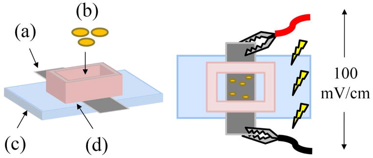
An (a) NGC strip is secured on top of a (c) microscope slide with a (d) polycarbonate well and vacuum grease. (b) Cells in media are cultured in the well and exposed to an EF 100 mV/cm using electrodes attached to the ends of the strip.
Immunohistochemistry of DRG cultures
Following stimulation of DRGs on film strips, samples were allowed 72 h to extend axons before fixation. Samples were permeabilized with 0.25% Triton-X 100 for 20 min, washed three times with PBS, then stained against β-III tubulin (Abcam, Cambridge, MA) diluted 1:1000 in blocking solution containing 3% goat serum in PBS and kept at 4°C overnight. The samples were washed then counter-stained with a secondary antibody conjugated with Alexafluor 488 diluted 1:1000 and incubated at 4°C overnight. Samples were washed then stored in PBS before imaging.
Cell adhesion and cytotoxicity on NGC material
Earlier studies by Durgam et al.21 demonstrated pre-stimulation of PPy material before cell exposure reduces toxicity. In the present study, NGC strips were pre-stimulated by applying 100 mV/cm DC current for 2 h, while submerged under media. Media was then aspirated, washed with PBS, rinsed with DI water, and allowed to air dry. PC12 cells were seeded onto the surface and stimulated using the same protocol, cultured for 24 h, then stained with calcein-AM and ethidium homodimer-1 (Live/dead kit, Invitrogen, Carlsbad, CA). Fluorescent images of stained cells were processed with ImageJ (open source NIH software) to observe cell morphology and measure cell adhesion on the surface of pre-stimulated and non-prestimulated (original) NGCs.
Cell imaging and data analysis
Field emission scanning electron microscopy (FE-SEM) (Amray SEM-EDX 1200, Amray Inc., Bedford, MA) was used to qualitatively evaluate the structure and surfaces of the NGCs. A sample was placed on a metallic stub adhered with silver paint without sputter coating to observe the charging effects of the PLGA layer.
Optical images were obtained with an inverted phase contrast/fluorescent microscope (Olympus IX-70, Olympus Corporation, Tokyo, Japan) with an attached color CCD camera (MagnaFire S60800, Optronics, Goleta, CA), and analyzed with ImageJ. Extended processes from DRGs that fluoresced brightly (indicating greater thickness) and were 1x longer than the DRG diameter were measured. Axon length was measured by drawing a straight line from the body to the tip of the axon. For axons that branched or curved, a single line measurement was made to represent the average length and direction. The axon angle θ was measured between the line measurement and the long axis of the NGC (direction of ES), where the cathode is directed toward the positive x-axis.
All data reported are mean values with standard error. Statistical significance was calculated using an unpaired, unequal variance, two-tailed Student’s t-test to compare ES samples with the non-ES control from each group. Significance was defined as a p < 0.05.
RESULTS AND DISCUSSION
Synthesis of PPy-PCL
PPy-PCL block copolymers were synthesized using a two-step process21,33: a poly(caprolactone)diol was first reacted with butyl lithium and then with 2-(trichloroacetyl)pyrrole to form an oligomeric polycaprolactone segment that was terminated with two pyrrole units (Figure 3, top reaction). This macromonomer was then copolymerized with freshly distilled pyrrole in the presence of ferric para-toluenesulfonate [Fe(PTS)3] or ferric perchlorate [Fe(ClO4)3] in acetonitrile. Pyrrole and the di-pyrrole terminated macromonomer will copolymerize under these conditions because they have similar oxidation potentials.33 The product was purified and re-dispersed by repeated centrifugation and decanting cycles.34 Both Capa 2205 and Capa 2200P were used to make copolymers at ratios of pyrrole to macromonomer of 1:2 and 1:1. The various samples showed little differences in bulk conductivity and dispersion characteristics (Table 1) tentatively indicating the four PTS-doped materials to have very similar properties with electrical conductivity ranging 10–20 S/cm. We speculate that during synthesis, the copolymer may be driven to a certain favored composition in spite of the monomeric feed ratio. The perchlorate-doped copolymer also had similar conductivities but resulted in lower yields of purified copolymer. Since we found that PTS-doped PPy-PCL had good biocompatibility in prior work21 we decided to use a PTS-doped 2:1 copolymer of Capa-2200P for the remaining experiments.
Figure 3.

Synthesis of PTS doped polypyrrole-co-polycaprolactone (PPy-PCL) copolymer.
Table 1.
Yield of synthesis, bulk conductivity, and dispersion quality in nitromethane of copolymers of polypyrrole and polycaprolactone of various composition.
| Macromonomer | Macromonomer: PPy Ratio | Oxidizing Agent | Yield after purification | Bulk Conductivity (S cm−1) | Dispersion in Nitromethane |
|---|---|---|---|---|---|
| CAPA2200PdiPy | 1:1 | Fe(PTS)3 | 51% | 13 | good |
| CAPA2200PdiPy | 2:1 | Fe(PTS)3 | 63% | 16 | good |
| CAPA2205diPy | 1:1 | Fe(PTS)3 | 9.9 | good | |
| CAPA2205diPy | 2:1 | Fe(PTS)3 | 75% | 16 | good |
| CAPA2200PdiPy | 1:1 | Fe(ClO4)3 | 53% | 17.4 | good |
| CAPA2200PdiPy | 2:1 | Fe(ClO4)3 | 23% | 21.5 | good |
PPy-PCL degradation
The hydrolysis of 2:1 PPy-PCL (PTS-doped) pressed pellets soaked in various buffer solutions was followed for 11 months. Each weight measurement was taken as the average of the % weight loss of 5 pellets. Error bars are not shown on the plots in Figure 4 to simplify the graphs, but are available.
Figure 4.

Weight loss with time of PPy-PCL at pH of 4.15 (blue diamond), 7.3 (pink circle) and 9.0 (yellow triangle) for (a) the first 7 d and (b) up to 11 months.
Figure 4 shows the % weight of the pellets at the 3 pH levels for the first 200 h and the entire 11 months, indicating degradation is faster in basic buffers. This is surprising because PCL is a polyester, and polyesters typically degrade faster at lower pH. At pH 7.3 the pellets lose approximately 15% of their weight in the first day, another 15% in the first week, and from thereon, the degradation rate gradually declines. At 1340 h into the experiment, we decided to test whether the frequency of weighing and replacing buffer solutions affected the degradation rate, so the solution was changed every day for a few days. This increased the noise in the curve (glitches in the 11 month graph), but did not change the overall trend of the curve, so the original protocol was resumed. It was surprising to observe that weight gain occurred near 6000 h (8.3 months), especially at pH 7 and 9. This was then followed by embrittlement and cracking, which made it difficult to continue the experiment.
Domingos et al. reported temporary weight gain of PCL specimens during hydrolysis at pH 7 after 4–6 months, but did not provide an explanation for the weight gain.35 We believe this could be due to addition of water molecules to the ester bonds before chain break-up. Hydrolysis of polyesters is known to be self-catalyzed by the products of degradation and fragmented chain ends, both of which contain carboxylic acid groups, and when self-catalyst occurs catastrophic failures have been observed, at least for polylactic acid implants.36 This could be consistent with what was observed at the end of the experiments, but additional investigation is needed.
FT-IR spectra of the starting pelletized copolymer and the remaining fragmented pellets from the hydrolysis experiments were recorded in KBr pellets with a Nicolet Instrument. Figure 5a shows the FT-IR spectra of the pristine polymer (red) and after 11 months at pH 4 (blue), pH 7 (purple) and pH 9 (green). The interpretation of the spectra is complicated by the presence of the polaron conducting band of PPy which distorts the baseline of the spectrum from 2000 to 4000 cm−1. Despite the baseline distortion the pristine polymer clearly shows the N-H stretching band of the pyrrole rings at 3400 cm−1. This band is also visible as a shoulder in the samples after hydrolysis. Upon degradation a very broad OH stretching band is formed, which peaks at 3100 cm−1. The band is stronger in the pellets that have been degraded at pH 7 and 9 and has lower intensity for the pellets at pH 4. The presence of this band suggests the presence of hydrogen-bonded hydroxyl and carboxylic acid groups, which is consistent with hydrolysis of the PCL blocks. Formation of hydroxyl groups may also result from the oxidation of pyrrole rings in position 3. This band may also include the NH2+ stretching of protonated pyrrole rings. We can exclude the possibility that this OH band is simply due to absorbed water because of the absence of a band at 1640 cm−1, which is the V2 bending mode of sorbed water. The spectra at lower wave-numbers (Figure 5b) show strong bands are formed at 1560, 1290 and 775 cm−1 during hydrolysis, the intensity of which is nearly independent of pH. The presence of these bands may indicate the presence of carboxylate anions, which would result from the hydrolysis of the PCL blocks.
Figure 5.

(a) FT-IR spectra of pristine PPy-PCL (red), and after 11 months at pH 4 (blue), pH 7 (purple) and pH 9 (green), and (b) a closer examination in the 1800-400 cm−1 region.
On the basis of these results, we attribute the early weight loss to leaching of the dopant (PTS) and traces of iron from the conducting PPy blocks of the copolymer. After the first week, the weight loss is due to further leaching of PTS from inner regions of the pellets as well as beginning of surface degradation of the PCL blocks. The total theoretical amount of PTS in PPy-PCL is 28 wt% (calculated as the weight fraction of PTS in the copolymer formula shown at the bottom of Fig. 1) and the total amount of iron is insignificant (200 ppm), therefore any weight loss above 28% would be due to fragmentation of the polymer backbone. Since all pyrrole oligomers and byproducts are highly colored (red, brown, or black), the lack of coloration in the hydrolysis products suggests that fragmentation of the PPy chain did not occur, or if it occurred, it was accompanied by ring opening and loss of conjugation. Weight gain followed by catastrophic failure at 6–8 months is attributed to addition of water by the ester bonds and self-catalyzed degradation of the PCL blocks. This interpretation is confirmed by the FT-IR spectra of the remaining pellets after hydrolysis that shows no evidence of absorbed water. Overall, this study confirmed that our copolymer degrades under a variety of aqueous conditions.
Fabrication of NGC
Mechanically strong seamless NGC cylindrical tubes were fabricated with an outer layer of PLGA and an inner layer of PPy-PCL (Figure 6). The tubes are 1.1 or 6.1 mm in diameter, 12 mm in length, and have an average resistance of 4 kΩ. They are on average 30 μm thick, of which 12–24 μm is the PPy-PCL. The conduits have good mechanical properties; they are easy to suture with either 5-0 or 10-0 gauge needle and thread, and could be pierced without tearing. Figure 7 shows an FE-SEM image of a conduit where the outer layer glows bright due to charging of the insulative PLGA layer while the conductive inner layer remains dark.
Figure 6.
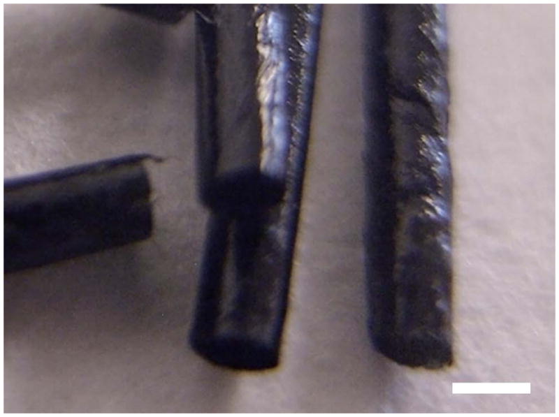
Macro-photo of seamless cylindrical, electrically conducting and biodegradable NGCs with PLGA outer layer and PPy-PCL inner coating. Scale is 1 mm.
Figure 7.
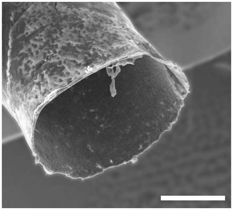
FE-SEM image of an NGC tube end; the bright halo is due to charging of the outer PLGA layer. Scale is 500 μm.
Evaluation of NGC conductive integrity
A strip of PLGA-coated PPy-PCL was submerged in PBS and ends kept dry to attach electrodes. A constant 1, 10, or 100 μA current was conducted across the strips while DC voltage was recorded during ES. Resistance of the entire unit was calculated in Table 2, showing the increase in resistance as the current intensity increases. After 20 min stimulation, a 1 μA current did not change material conductivity whereas 10 μA gradually reduced strip conductivity to 19 kΩ. After 24 h continuous stimulation, 1–10 μA reduced the resistance of the material to 40 kΩ. At 100 μA, loss of conductivity occurred within the first minute of stimulation, likely due to rapid electrochemical overoxidation of PPy.37
Table 2.
Initial and final resistance of NGC strips in PBS when stimulated under various current intensity.
| Current (μA) | Initial R (kΩ) | R 20 min (kΩ) | R 24 h (kΩ) |
|---|---|---|---|
| 1 | 10 | 10 | 40 |
| 10 | 10 | 19 | 40 |
| 100 | 10 | 2000 | - |
An average current of 1–10 μA is equivalent to an EF strength of 100 mV/cm through the NGC film strip. At this EF strength, the device is expected to remain conductive and able to deliver stimulation throughout its therapeutic lifetime.21 It is interesting to note that, when measured after experimentation, the greatest change in electrical resistance of a PPy-PCL/PLGA strip was located at the interface between air and saline buffer on the anodic side of the material. We believe this may be attributed to redox reactions occurring in saline near the anode, leading to overoxidation of the material. Improving conductive stability under physiological conditions will need further investigation, nevertheless, these findings indicate the NGC retains the ability to expose tissue to an EF for at least 24 h.
PC12 cell adhesion and cytotoxicity on stimulated NGC strips
Although polymerized PPy materials are non-toxic, pyrrole monomer and short chain oligomers present in the starting materials can be toxic. Residues of these chemicals may be embedded within the bulk of the final product and can elicit various degrees of cytotoxicity. To address this issue, multiple washes and early ES of the material has been shown to reduce cell death. 21,38 The reduction of both conductivity and cytotoxicity with washing and ES methods is likely a complex combination of solvent swelling, partial red-ox reactions, hydrolytic degradation of PPy, ion exchange, and current induced morphological changes in the conducting film, but we did not attempt to elucidate the full mechanism. For the purposes of this study, our concern was the removal of any endogenous toxicity that our films possibly possessed prior to our in vitro studies, and this step was called pre-stimulation.
PC12 cell viability and adhesion was evaluated when grown on the inner PPy-PCL layer of the NGC without ECM coating. Cells were seeded on bare polymer and given 1 d to adhere to the strip. The cells were then stained with a live/dead fluorescent kit to differentiate live spread cells and dead cells on the material. The ratio of live:dead PC12 cells when cultured on pre-stimulated and control NGC films did not change, the ratio was similar to cells grown on tissue culture plastic (data not shown)(Figure 8).
Figure 8.

PC12 cell viability on PPy-PCL substrates was measured with live/dead (green/red) staining. (a, b) PC12 cells grown on the pre-stimulated strips without ES and (c, d) PC12 cells grown on non-pre-stimulated strips show that the ratio of live:dead cells remain similar. Scale is 100 μm.
To measure cell adherence, ImageJ software was used to threshold the fluorescent images of PC12 cells stained with calcein to reveal the surface area covered by cell spreading. The total number of cells adhered to the substrate was approximated by dividing the total amount of cell coverage within a single image by the average surface area covered by an individual cell. One representative image was taken per NGC strip. PC12 cells were cultured on both pre-stimulated NGC (PS) and without pre-stimulation (NonPS). For both substrates, cells were exposed to DC EF (ES, n=12 each) and without (control, n=4 each). The average number of PC12 cells adhering to NonPS was between 5020–5880 cells/cm2 (±1340, standard error) whereas the average cell count for PS was 1540–2400 cells/cm2, (± 380) as shown in Figure 9. Cell count was significantly different between NonPS and PS groups (p<0.01) but not between control and ES groups. Cell ES did not appear to have any significant short term effects on adhesion.
Figure 9.

The total amount of live cells on pre-stimulated (PS) and non-pre-stimulated (NonPS) substrates are the similar before and after stimulation. However, the number of cells adhering to the surface of NonPS is two times greater than on PS films (w/standard error).
In contrast to previous studies21,38, pre-stimulating the NGC did not change substrate cytotoxicity, but reduced cell adhesion to the PPy-PCL surface. The reason for this is unknown, but we suspect that pre-stimulating in PBS may have de-doped the sample and replaced PTS with salts in the solution. The surface charge would be balanced but less prone to protein replacement because pristine surfaces of PPy-PCL are more susceptible to protein adsorption, promoting cell adhesion. It is also possible that more PCL may have been exposed when dopants were removed which is typically not cell adhesive39 and change in hydration due to stimulation can influence cellular attachment.40 Nevertheless, there was no change in toxicity when the NGC strip was stimulated with 100 mV/cm DC for 2 h before or after cell culture, the ratio of live:dead cells was the same for all conditions. This novel method for fabricating NGCs demonstrated that cytotoxicity may not be an issue and pre-stimulation of the material is not needed. Thus, all following experiments were performed on NonPS NGC strips.
DRG axon extension on stimulated NGC strips
DRGs were embedded in a thin layer of Matrigel on top of the PPy-PCL surface of an NGC strip. Freshly extracted DRGs were allowed to acclimate for 1 d on the surface, exposed to an EF for 2 h, allowed 3 d to extend axons, fixed, stained for β-III-tubulin, and imaged. Because there were many processes extending from a single DRG body, only thick axons that were visibly discernible were measured for analysis. These axons were also the longest processes extending from the ganglion, as shown in Figure 10.
Figure 10.

A DRG embedded in Matrigel on top of a PPy-PCL strip was given 1 d to grow in the gel, stimulated for 2 h with DC 100 mV/cm, and allowed to grow for another 3 d before imaging. The DRG body (bright center) is surrounded by a cloud of axons and migrating Schwann cells. The longer processes extending beyond the cloud were measured. Scale is 1 mm.
There were 24 DRGs with approximately n=340 axons counted for each of the control and experimental groups. DRGs grown on NGCs without ES had an average axon length of 821 μm (± 17, standard error). DRGs grown on NGC strips stimulated with a 100 mV/cm DC signal for 2 h had axons with an average length of 927 μm (± 15), increasing growth by 13% (p<0.01), summarized in Table 3. DRG cultures stimulated with 60 Hz AC 100 mV/cm for 2 h had axons with an average length of 996 μm (± 21), increasing growth by 21% (p≪0.01). Further studies are necessary to explore the mechanism behind this difference in cell response to DC versus AC signals. Although both stimulation methods increased axon length, AC stimulation has greater clinical relevance because of decreased cytotoxic Faradaic components typically produced from DC electrodes.
Table 3.
Average DRG axon length when stimulated with DC and AC EF
| Average axon length (μm) | Standard Deviation | Standard Error | Student’s t-test | ||
|---|---|---|---|---|---|
| Control | 821 | 302 | 17 | 334 | |
| DC EF | 927 | 278 | 15 | p ≪ 0.001 | 358 |
| AC EF | 996 | 343 | 21 | p ≪ 0.001 | 281 |
We observed that DRGs tended to extend axons towards the closest electrode when stimulated with a DC signal (Figure 11). Because there were two DRGs for each NGC sample, one lied closer to the cathode and the other towards the anode. The DRGs were placed 5mm apart so their growth was not influenced by the other’s presence and each DRG was equidistant from edges of the Matrigel surrounding it, depicted in Figure 12. DRGs closer to the anode (labeled as DRG 1) and DRGs closer to the cathode (labeled as DRG 2) were grouped independently. On average, DRGs in position 1 extended axons more towards the left (anode) by 160 μm and DRGs in position 2 extended axons more towards the right (cathode) by 115 μm, as shown in Figure 13. The average axon growth perpendicular to the EF direction was not significantly different than controls. Furthermore, this observation was not observed when substrates were stimulated with an AC signal.
Figure 11.
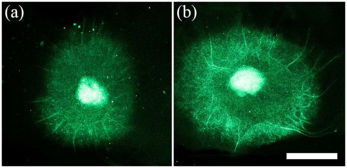
Fluorescent images of DRGs grown on PPy-PCL (A) without ES and (B) with ES show DC EF exposure can increase axon length unilaterally. Scale is 1 mm.
Figure 12.
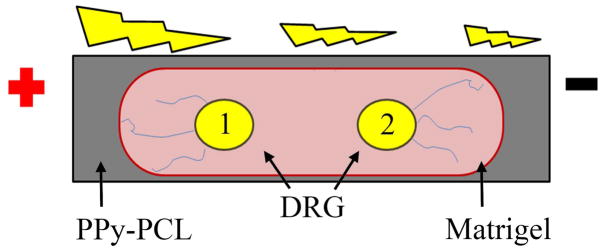
A schematic of the stimulation experiment shows positioning of two DRGs embedded in Matrigel on top of an NGC strip. DRG 1 is located near the anode and DRG 2 is located near the cathode. The drawing emphasizes greater axon extension towards the nearest electrode when exposed to DC EF.
Figure 13.

The x- and y-components of DRG axon measurements (axon growth parallel and perpendicular to the DC EF) showed neurons near an electrode extended longer axons towards that electrode. Axons growing parallel to the EF was significantly longer than control samples (* = p<0.05), while axons perpendicular to the EF was not.
A DC EF has been known to induce unilateral growth/migration41,42, perpendicular alignment43, or increased growth with no polarized alignment44,45, but there have been no reports of cell growth towards both electrodes. There is a possibility that gel towards the edge was thinner and promoted nutrient/waste transfer more quickly compared to the center, however this does not explain why axons did not extend in the perpendicular direction where the gel was also thin. Because the EF creates an ionic current through the material, gel, and media, the current may influence transport and structural organization in the gel, leading to greater axon growth near the sources of the current.
CONCLUSION
A novel biodegradable conductive PPy-PCL conduit with a laminated PLGA coating was assessed for its ability to be an effective NGC. To supply an EF in vivo for an extended period of time, PPy was chosen because of its electrical conductivity, biocompatibility, and ease in manufacturing, while PCL and PLGA were chosen for their tailorable mechanical properties and biodegradability. Under physiological conditions, the conduit was flexible yet sturdy, retained conductivity of endogenous EF strengths for at least 24 h, and will degrade within the body.
Previous studies by Durgam et al.21 indicated similar materials needed to be rendered cytocompatible through pre-stimulation, but it was found that the current iteration of the PPy-PCL did not need this extra process. In fact, twice as many PC12 cells adhered on pristine NGC.
Primary DRGs were then cultured on the PPy-PCL/PLGA strips. When electrically stimulating DRGs, it was found that 100 mV/cm DC EF for 2 h increased average axon length by 13% and 100 mV/cm AC EF for 2 h increased axon length by 21%, when measured 3 d after stimulation. DRGs extended axons towards the nearest electrode under DC stimulation, but was not observed in AC stimulation, suggesting that current flow through the substrate may affect transport or the ECM structure adjacent to the surface. Future studies will include stimulation of DRG axons ensheathed by the original cylindrical NGC to assess device efficacy in a more clinically relevant situation.
The results shown in this study demonstrate that conductive PLGA-coated PPy-PCL is a promising material for tissue engineering and has potential for use in other applications such as bioelectrical interfaces32, drug delivery46, and cancer therapy.47,48 In summary, a biodegradable, electrically conductive PPy-PCL substrate is an effective means to deliver EF growth cues to enhance axon growth for nerve repair.
Acknowledgments
The work presented was funded by the NIH SBIR R43 NS 062593-01. The authors were supported by the Department of Defense National Defense Science and Engineering Graduate fellowship, the University of Texas at Austin Undergraduate Research Fellowships, and Intellectual Entrepreneurship funding.
References
- 1.Schmidt CE, Leach JB. Neural tissue engineering: strategies for repair and regeneration. Annu Rev Biomed Eng. 2003;5:293–347. doi: 10.1146/annurev.bioeng.5.011303.120731. [DOI] [PubMed] [Google Scholar]
- 2.Midha R. Emerging techniques for nerve repair: nerve transfers and nerve guidance tubes. Clin Neurosurg. 2006;53:185–190. [PubMed] [Google Scholar]
- 3.Campbell W. Evaluation and management of peripheral nerve injury. Clin Neurophysiol. 2008;119:1951–1965. doi: 10.1016/j.clinph.2008.03.018. [DOI] [PubMed] [Google Scholar]
- 4.Kehoe S, Zhang XF, Boyd D. FDA approved guidance conduits and wraps for peripheral nerve injury: a review of materials and efficacy. Injury. 2012;43:553–572. doi: 10.1016/j.injury.2010.12.030. [DOI] [PubMed] [Google Scholar]
- 5.Hoke A, Brushart T. Challenges and opportunities for the regeneration in the peripheral nervous system. Exp Neurol. 2010;223:1–4. doi: 10.1016/j.expneurol.2009.12.001. [DOI] [PMC free article] [PubMed] [Google Scholar]
- 6.Altizer AM, Moriarty LJ, Bell SM, Schreiner CM, Scott WJ, Borgens RB. Endogenous electric current is associated with normal development of the vertebrate limb. Dev Dynam. 2001;221:391–401. doi: 10.1002/dvdy.1158. [DOI] [PubMed] [Google Scholar]
- 7.McCaig CD, Rajnicek AM, Song B, Zhao M. Has electrical growth cone guidance found its potential? Trends Neurosci. 2002;25:354–359. doi: 10.1016/s0166-2236(02)02174-4. [DOI] [PubMed] [Google Scholar]
- 8.Nuccitelli R. Endogenous electric fields in embryos during development, regeneration and wound healing. Radiat Prot Dosim. 2003;106:375–383. doi: 10.1093/oxfordjournals.rpd.a006375. [DOI] [PubMed] [Google Scholar]
- 9.Henley J, Poo M. Guiding neuronal growth cones using Ca2+ signals. Trends Cell Biol. 2004;14:320–330. doi: 10.1016/j.tcb.2004.04.006. [DOI] [PMC free article] [PubMed] [Google Scholar]
- 10.McCaig CD, Rajnicek AM, Song B, Zhao M. Controlling cell behavior electrically: current views and future potential. Physiol Rev. 2005;85:943–978. doi: 10.1152/physrev.00020.2004. [DOI] [PubMed] [Google Scholar]
- 11.Levin M. Bioelectric mechanisms in regeneration: unique aspects and future perspectives. Semin Cell Dev Biol. 2009;20:543–556. doi: 10.1016/j.semcdb.2009.04.013. [DOI] [PMC free article] [PubMed] [Google Scholar]
- 12.Zhao M. Electrical fields in wound healing - an overriding signal that directs cell migration. Semin Cell Dev Biol. 2009;20:674–682. doi: 10.1016/j.semcdb.2008.12.009. [DOI] [PubMed] [Google Scholar]
- 13.Patel NB, Poo M. Perturbation of the direction of neurite growth by pulsed and focal electric fields. J Neurosci. 1984;4:2939–2947. doi: 10.1523/JNEUROSCI.04-12-02939.1984. [DOI] [PMC free article] [PubMed] [Google Scholar]
- 14.Wong J, Ingber D, Langer R. Electrically conducting polymers can noninvasively control the shape and growth of mammalian cells. Proc Nat Acad Sci USA. 1994;91:3201–3204. doi: 10.1073/pnas.91.8.3201. [DOI] [PMC free article] [PubMed] [Google Scholar]
- 15.Schmidt CE, Shastri VR, Vacanti JP, Langer R. Stimulation of neurite outgrowth using an electrically conducting polymer. Proc Nat Acad Sci USA. 1997;94:8948–8953. doi: 10.1073/pnas.94.17.8948. [DOI] [PMC free article] [PubMed] [Google Scholar]
- 16.Kimura K, Yanagida Y, Haruyama T, Kobatake E, Aizawa M. Electrically induced neurite outgrowth of PC-12 cells on the electrode surface. Med Biol Eng Comput. 1998;36:493–498. doi: 10.1007/BF02523221. [DOI] [PubMed] [Google Scholar]
- 17.Garner B, Georgevich B, Hodgson A, Liu L, Wallace G. Polypyrrole-heparin composites as stimuli-responsive substrate for endothelia cell growth. J Biomed Mater Res. 1999;44:121–129. doi: 10.1002/(sici)1097-4636(199902)44:2<121::aid-jbm1>3.0.co;2-a. [DOI] [PubMed] [Google Scholar]
- 18.Kotwal A, Schmidt CE. Electrical stimulation alters protein adsorption and nerve cell interactions with electrically conducting biomaterials. Biomaterials. 2001;22:1055–1064. doi: 10.1016/s0142-9612(00)00344-6. [DOI] [PubMed] [Google Scholar]
- 19.Gomez N, Lee JY, Nickels JD, Schmidt CE. Micropatterned polypyrrole: combination of electrical and topographical characteristics for stimulation of cells. Adv Funct Mater. 2007;17:1645–1653. doi: 10.1002/adfm.200600669. [DOI] [PMC free article] [PubMed] [Google Scholar]
- 20.Quigley AF, Razal JM, Thompson BC, Moulton SE, Kita M, Kennedy EL, Clark GM, Wallace GG, Kapsa RMI. A conducting polymer platform with biodegradable fibers for stimulation and guidance of axonal growth. Adv Mater. 2009;21:4393–4397. doi: 10.1002/adma.200901165. [DOI] [PubMed] [Google Scholar]
- 21.Durgam H, Sapp S, Deister C, Khaing Z, Chang E, Luebben S, Schmidt CE. Novel degradable co-polymers of polypyrrole support cell proliferation and enhance neurite outgrowth with electrical stimulation. J Biomater Sci Polym Ed. 2010;21:1265–1282. doi: 10.1163/092050609X12481751806330. [DOI] [PubMed] [Google Scholar]
- 22.Zhao M, Pu J, Forrester JV, McCaig CD. Membrane lipids, EGF receptors, and intracellular signals colocalize and are polarized in epithelial cells moving directionally in a physiological electric field. FASEB. 2002;6:857–859. doi: 10.1096/fj.01-0811fje. [DOI] [PubMed] [Google Scholar]
- 23.Kerns JM, Lucchinetti C. Electrical field effects on crushed nerve regeneration. Exp Neurol. 1992;117:71–80. doi: 10.1016/0014-4886(92)90112-4. [DOI] [PubMed] [Google Scholar]
- 24.Al-Majed AA, Neumann CM, Brushart TM, Gordon T. Brief electrical stimulation promotes the speed and accuracy of motor axonal regeneration. J Neurosci. 2000;20:2602–2608. doi: 10.1523/JNEUROSCI.20-07-02602.2000. [DOI] [PMC free article] [PubMed] [Google Scholar]
- 25.Brushart TM, Hoffman PN, Royall RM, Murinson BB, Witzel C, Gordon T. Electrical stimulation promotes motoneuron regeneration without increasing its speed or conditioning the neuron. J Neurosci. 2002;22:6631–6638. doi: 10.1523/JNEUROSCI.22-15-06631.2002. [DOI] [PMC free article] [PubMed] [Google Scholar]
- 26.Cheng WL, Lin CC. The effect of different electrical stimulation protocols on nerve regeneration through silicone conduits. J Trauma. 2004;56:1241–1246. doi: 10.1097/01.ta.0000071289.11767.22. [DOI] [PubMed] [Google Scholar]
- 27.English AW, Schwartz G, Meador W, Sabatier MJ, Mulligan A. Electrical stimulation promote peripheral axon regeneration by enhanced neurotrophin signaling. Dev Neurobiol. 2007;67:158–172. doi: 10.1002/dneu.20339. [DOI] [PMC free article] [PubMed] [Google Scholar]
- 28.Inoue M, Katsumi Y, Itoi M, Hojo T, Nakajima M, Ohashi S, Oi Y, Kitakoji H. Direct current electrical stimulation of acupuncture needles for peripheral nerve regeneration: an exploratory case series. Acupunct Med. 2011;29:88–93. doi: 10.1136/aim.2010.003046. [DOI] [PubMed] [Google Scholar]
- 29.Kim J, Han SJ, Shin DH, Lee WS, Choi JY. Subthreshold continuous electrical stimulation facilitates functional recovery of facial nerve after crush injury in rabbit. Muscle Nerve. 2011;43:251–258. doi: 10.1002/mus.21840. [DOI] [PubMed] [Google Scholar]
- 30.Wang X, Gu X, Yuan C, Chen S, Zhang P, Zhang T, Yao J, Chen F, Chen G. Evaluation of biocompatibility of polypyrrole in vitro and in vivo. J Biomed Mater Res A. 2003;68:411–422. doi: 10.1002/jbm.a.20065. [DOI] [PubMed] [Google Scholar]
- 31.Guimard NK, Gomez N, Schmidt CE. Conducting polymers in biomedical engineering. Prog Polym Sci. 2007;32:876–921. [Google Scholar]
- 32.Bendrea AD, Cianga L, Cianga I. Review paper: progress in the field of conducting polymers for tissue engineering applications. J Biomat Applications. 2011;26:3–84. doi: 10.1177/0885328211402704. [DOI] [PubMed] [Google Scholar]
- 33.Luebben S, Elliott B, Wilson C. Poly(heteroaromatic) block copolymers with electrical conductivity. 7,279,534. US Patent. 2007
- 34.Luebben S, Sapp S. Methods of production, purification, and processing of poly(heteroaromatic) block copolymers with improved solubility or dispersability. 7,687,582. US Patent. 2010
- 35.Domingos M, Chiellini F, Cometa S, De Giglio E, Grillo-Fernandes E, Bartolo P, Chiellini E. Evaluation of in vitro degradation of PCL scaffolds fabricated via bioextrusion. Part 1: Influence of the degradation environment. Virtual Phys Prototyp. 2010;5:65–73. [Google Scholar]
- 36.Andriano KP, Tabata Y, Ikada Y, Heller J. In vitro and in vivo comparison of bulk and surface hydrolysis in absorbable polymer scaffolds for tissue engineering. J Biomed Mater Res. 1999;48:602–612. doi: 10.1002/(sici)1097-4636(1999)48:5<602::aid-jbm3>3.0.co;2-6. [DOI] [PubMed] [Google Scholar]
- 37.Ateh DD, Navsaria HA, Vadgama P. Polypyrrole-based conducting polymers and interactions with biological tissues. J R Soc Interface. 2006;3:741–752. doi: 10.1098/rsif.2006.0141. [DOI] [PMC free article] [PubMed] [Google Scholar]
- 38.Fonner JM, Forciniti L, Nguyen H, Byrne J, Kou YF, Syeda-Nawaz J, Schmidt CE. Biocompatibility implications of polypyrrole synthesis techniques. Biomed Mater. 2008;3:1–12. doi: 10.1088/1748-6041/3/3/034124. [DOI] [PMC free article] [PubMed] [Google Scholar]
- 39.Tang ZG, Black RA, Curran JM, Hung JA, Rhodes NP, Williams DF. Surface properties and biocompatibility of solvent-cast poly[ε-caprolactone] films. Biomaterials. 2004;25:4741–4748. doi: 10.1016/j.biomaterials.2003.12.003. [DOI] [PubMed] [Google Scholar]
- 40.Guiseppi-Elie A, Dong C, Dinu CZ. Crosslink density of biomimetic poly(HEMA)-based hydrogel influences growth and proliferation of attachment dependent RMS 13 cells. J Mater Chem. 2012;22:19529–19539. [Google Scholar]
- 41.McKasson MJ, Huang L, Robinson KR. Chick embryonic Schwann cells migrate anodally in small electrical fields. Exp Neurol. 2008;211:585–587. doi: 10.1016/j.expneurol.2008.02.015. [DOI] [PMC free article] [PubMed] [Google Scholar]
- 42.Messerli MA, Graham DM. Extracellular electrical fields direct wound healing and regeneration. Biol Bull. 2011;221:79–92. doi: 10.1086/BBLv221n1p79. [DOI] [PubMed] [Google Scholar]
- 43.Ariza CA, Fleury AT, Tormos CJ, Petruk V, Chawla S, Oh J, Sakaguchi DS, Mallapragada SK. The influence of electric fields on hippocampal neural progenitor cells. Stem Cell Rev. 2010;6:585–600. doi: 10.1007/s12015-010-9171-0. [DOI] [PubMed] [Google Scholar]
- 44.Wood MD, Willits RK. Applied electric field enhances DRG neurite growth: influence of stimulation media, surface coating and growth supplements. J Neural Eng. 2009;6:1–8. doi: 10.1088/1741-2560/6/4/046003. [DOI] [PubMed] [Google Scholar]
- 45.Koppes AN, Seggio AM, Thompson DM. Neurite outgrowth is significantly increased by the simultaneous presentation of Schwann cells and moderate exogenous electric fields. J Neural Eng. 2011;8:1–13. doi: 10.1088/1741-2560/8/4/046023. [DOI] [PubMed] [Google Scholar]
- 46.Ravichandran R, Sundarrajan S, Venugopal JR, Mukherjee S, Ramakrishna S. Applications of conducting polymers and their issues in biomedical engineering. J R Soc Interface. 2010;7:S559–579. doi: 10.1098/rsif.2010.0120.focus. [DOI] [PMC free article] [PubMed] [Google Scholar]
- 47.Garon EB, Sawcer D, Vernier PT, Tang T, Sun Y, Marcu L, Gundersen MA, Koeffler HP. In vitro and in vivo evaluation and a case report of intense nanosecond pulsed electric field as a local therapy for human malignancies. Int J Cancer. 2007;121:675–682. doi: 10.1002/ijc.22723. [DOI] [PubMed] [Google Scholar]
- 48.Kirson ED, Dbaly V, Tovarys F, Vymazal J, Soustiel JF, Itzhaki A, Mordechovich D, Steinberg-Shapira S, Gurvich Z, Schneiderman R, Wasserman Y, Salzberg M, Ryffel B, Goldsher D, Dekel E, Palti Y. Alternating electric fields arrest cell proliferation in animal tumor models and human brain tumors. P Natl Acad Sci. 2007;104:10152–10157. doi: 10.1073/pnas.0702916104. [DOI] [PMC free article] [PubMed] [Google Scholar]