Abstract
Plasma enhanced chemical vapor deposition (PECVD) of perfluoroalkanes has long been studied for tuning the wetting properties of surfaces. For high surface area microporous materials, such as metal-organic frameworks (MOFs), unique challenges present themselves for PECVD treatments. Herein the protocol for development of a MOF that was previously unstable to humid conditions is presented. The protocol describes the synthesis of Cu-BTC (also known as HKUST-1), the treatment of Cu-BTC with PECVD of perfluoroalkanes, the aging of materials under humid conditions, and the subsequent ammonia microbreakthrough experiments on milligram quantities of microporous materials. Cu-BTC has an extremely high surface area (~1,800 m2/g) when compared to most materials or surfaces that have been previously treated by PECVD methods. Parameters such as chamber pressure and treatment time are extremely important to ensure the perfluoroalkane plasma penetrates to and reacts with the inner MOF surfaces. Furthermore, the protocol for ammonia microbreakthrough experiments set forth here can be utilized for a variety of test gases and microporous materials.
Keywords: Chemistry, Issue 80, materials (general), gas absorption, low pressure chemistry, organometallic materials, Chemistry and Materials (General), Inorganic, Organic and Physical Chemistry, plasma enhanced chemical vapor deposition, fluorine chemistry, microporosity, metal-organic frameworks, hydrophobic, stability, breakthrough, ammonia, adsorption
Introduction
Metal-organic frameworks (MOFs) have become a leading class of porous materials for toxic gas removal1-3. MOFs have an unprecedented ability to tailor functionality for targeted chemical interaction. Cu-BTC (also known as HKUST-1 or Cu3(BTC)2) has been previously found to have an exceptionally high ammonia loading; however, this is at a cost of the material's structural stability4 . Further studies on Cu-BTC have indicated that moisture itself is capable of degrading the MOF structure, rendering it ineffective for many potential applications5,6,21. The structural instability of certain carboxylate containing MOFs in the presence of liquid water or high humidity has been a major deterrent to use in commercial or industrial applications7 .
It would be most ideal for MOFs used for chemical removal to have inherent stability in the presence of humidity. However, many MOFs with superior stability, such as UiO-66, have poor chemical removal capabilities, while many MOFs with open metal sites like MOF-74 and Cu-BTC have superior chemical removal capabilities2,4,8,9. The open metal sites in MOF-74 and Cu-BTC enhance the uptake of toxic gases such as ammonia, but these sites are also susceptible to binding water, poisoning the active sites and in many cases leading to structural breakdown. In order to preserve the chemical properties of a water unstable MOF, various attempts to enhance the water stability of MOFs have been made. MOF-5 has been shown to have an enhancement in moisture resistance upon thermal treatment, by creating a carbonaceous layer around the MOF; however, the increased hydrophobicity is at the expense of surface area and ultimately functionality10. MOF-5 has also been shown to have its hydrostability increased through doping with Ni2+ ions11. Furthermore, 1,4-diazabicyclo[2.2.2]octane containing MOFs (also known as DMOFs) have been used to show the tuning of water stability through incorporation of various pendant groups on the 1,4-benzene dicarboxylate linker12,13.
The lack of hydrostability of certain of MOFs, specifically ones with high toxic gas uptake, led to the use of plasma enhanced chemical vapor deposition (PECVD) of perfluoroalkanes to create fluorinated groups on the surfaces of the MOF to increase its hydrophobicity14. This technique offers the unique benefit that it can be used to alter any MOF containing aromatic hydrogens, as well as other potential functional groups on the inner surfaces of MOFs. However, the technique can be difficult to control due to the formation of highly reactive radicals in the plasma. The radicals not only react with the aromatic hydrogen atoms, but also with CFx groups already reacted onto the MOF surfaces. Careful control of the procedure is necessary to ensure pore blockage does not occur, rendering the MOF ineffective. This technique has been used by others to alter the wetting properties of carbon materials; however, to our knowledge it had never previously been used to enhance hydrostability of microporous material.15,16.
Protocol
1. Cu-BTC Synthesis and Preparation
Stir 12.5 ml of deionized water and 12.5 ml of dimethylformamide in a 100 ml screw cap jar for approximately 5 min.
Add 0.87 g (3.6 mmol) copper(II) nitrate trihydrate followed by 0.50 g (2.4 mmol) of trimesic acid to the solution in the jar and stir for approximately 5 min. The solution will turn blue in color. Place the capped jar in a preheated oven at 120 °C for approximately 24 hr.
Remove the jar from the oven. Once the jar has cooled to room temperature, recover the Cu-BTC crystals via vacuum filtration using filter paper rated to recover crystals greater than or equal to 2.5 μm. Rinse the resulting crystals with dichloromethane, ultimately placing the crystals in a fresh solution of dichloromethane.
Exchange the solvent every 24 hr and replace with fresh dichloromethane for the next three days to assist in the removal of the less volatile solvents from the pores of Cu-BTC.
Heat the Cu-BTC crystals to 170 °C in a vacuum oven or via a Schlenk line to remove any residual guest molecules from the material. Fully activated Cu-BTC should be deep blue to purple in color.
Confirm the structure and chemical make-up of Cu-BTC via powder x-ray diffraction and Fourier-transform infrared spectroscopy, respectively.
2. Plasma Enhanced Chemical Vapor Deposition of Perfluoroalkanes on Cu-BTC14
Prior to each experiment clean the plasma reactor and any glassware to be used in the plasma treatment with an air plasma at 50 W for at least 30 min. This removes any perfluoroalkane films that may have formed on the inner surfaces of the reaction chamber or the glassware from prior experiments.
Place a known amount of activated Cu-BTC in a 250 ml Pyrex bottle and spread throughout the bottle on its side to ensure a homogenous treatment. A permeable cloth should be placed around the neck of the bottle with a rubber band to minimize the amount of sample that is lost upon applying a vacuum.
Place the bottle in the plasma chamber. Apply a vacuum until the chamber reached a pressure ≤0.20 mbar for at least 30 min to remove any water that may have adsorbed onto the sample.
Connect the perfluoroalkane gas and adjust the regulator to a pressure within the specifications of the mass flow controller.
Adjust the mass flow controller to fill the reaction chamber with the appropriate amount of perfluoroalkane gas to maintain the desired pressure of the experiment. Rotate the bottle within the PECVD apparatus to create a more homogenous treatment of the powder.
Light the plasma with a 13.56 MHz RF generator, and tune the radio frequency with the L-C matching unit to maximize the power while minimizing the reflectance. Retune periodically throughout the treatment.
Once the treatment is complete, evacuate the chamber of any residual perfluoroalkane gas and then vent to atmospheric pressure. Remove the sample from the PECVD apparatus and recover the treated material from the sides of the bottle. An antistatic device should be used to recover the maximum amount of material.
Place the treated material in an oven at 120 °C to remove any unreacted perfluoroalkane gas. Then place the treated material in a desiccator to prevent adsorption of water from the atmosphere.
Rinse the residual material left in the bottle and filter to recover the waste for proper disposal.
Characterize the treated Cu-BTC with 20F magic angle spinning nuclear magnetic resonance, Fourier-transform infrared spectroscopy, and x-ray photoelectron spectroscopy.
3. Aging of Cu-BTC under Humid Conditions
Set the desired temperature and relative humidity of the environmental chamber and allow it to equilibrate.
Spread the sample out evenly in an open container and place in the environmental chamber for the desired amount of time.
Characterize the Cu-BTC sample with x-ray diffraction and a nitrogen isotherm at 77 K to determine the degree of degradation.
4. Ammonia Microbreakthrough Experiments2
Prepare a 14.6 L ballast of ammonia at 5,000 mg/m3 by first injecting an empty ballast with 210 ml of neat ammonia. Then fill the ballast with zero air to a pressure of 15 psi. Connect the ballast in line with the microbreakthrough apparatus.
Run a blank tube in the microbreakthrough apparatus to determine the feed signal. Set mass flow controllers for ammonia and dry air to 8 and 12 ml/min, respectively, to create a flow of 20 ml/min of 2,000 mg/m3 ammonia. Run a programmed method to control the gas chromatograph and photoionization detector to determine the feed signal of ammonia in the effluent. Moisture can be added to the system if desired by running part of the diluent stream through a temperature-controlled saturator cell at a rate necessary to achieve the required relative humidity.
Place a small amount of glass wool below the glass frit in a nominal 4 mm i.d. glass tube. Weigh approximately 10-15 mg of material into the tube. The mass used should result in approximately 55 mm3 of sorbent volume, resulting in a bed residence time of approximately 0.15 sec.
Flow dry air through the glass tube as it is heated to 150 °C for 1 hr to remove any adsorbed water. Weigh the sample after regeneration.
Place the sample in line and secure upright in a water bath set to 25 °C.
Set the mass flow controllers for ammonia and dry air to 8 and 12 ml/min, respectively, to create a flow of 20 ml/min at 2,000 mg/m3 ammonia while bypassing the sample to the fill lines with the feed gas.
Flow the ammonia stream through the sample and run a programed method to control the gas chromatograph and photoionization detector to monitor the concentration of ammonia in the effluent.
Once the effluent concentration has reached the feed concentration, switch off the ammonia stream and allow the sample to off-gas any ammonia that is not strongly adsorbed to the sample.
Remove the sample from the water bath for post-exposure analysis via x-ray diffraction and Fourier-transform infrared analysis.
Integrate the gas chromatograph signal vs. time data to determine the ammonia loading for the sample.
Representative Results
Within the representative results the authors chose to display the characteristics of a 0.50 g sample of Cu-BTC treated with hexafluoroethane (C2F6) for 4 hr at a pressure of 0.30 mbar and a plasma power of 50 W. MOFs treated with a perfluoroalkane plasma under adequate conditions should display enhanced hydrophobicity. This can be demonstrated by placing the powder on top of liquid water and determining if the sample floats or measuring the contact angle water on a pressed pellet as seen in Figure 1. The contact angle for the Cu-BTC and the C2F6 plasma treated Cu-BTC pellets were measured to be 59° and 123°, respectively. The presence of CFx groups on the surface of the pores adds to the hydrophobicity of the material causing the material to repel water.
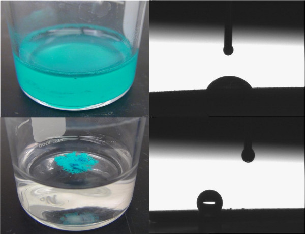 Figure 1. Pictures of Cu-BTC dispersed in water (top, left) and C2F6 plasma treated Cu-BTC repelling and floating on top of water (bottom, left). Contact angle images of Cu-BTC (top, right) and C2F6 plasma treated Cu-BTC (bottom, right) with a 2 μl droplet of water.
The presence of C-F bonds are indicated by spectral bands between 1,300-1,140 cm-1 in the attenuated total reflectance-Fourier-transform infrared spectroscopy (ATR-FTIR) results, as can be seen in Figure 217. The degree of fluorination and confirmation of CFx species type can be done with 20F magic angle spinning (MAS) nuclear magnetic resonance (NMR), as can be seen in Figure 3, or x-ray photoelectron spectroscopy (XPS). The two main fluorine species observed in this sample are CF2 groups at δ ~ -87 ppm and CF at δ ~ -152 ppm18. There is a small peak at δ ~ -80 ppm, representing CF3 groups. All other significant peaks represent spinning sidebands at approximately 9 kHz intervals from the parent peak. The CFx groups are likely a combination of groups that have reacted with the inner surfaces of the MOF, as well as an amorphous coating on the outside of the MOF crystal. The large size and quantity of spinning sidebands for the CF2 and CF species indicate that these CFx groups are tightly bound to the Cu-BTC structure and relatively immobile19.
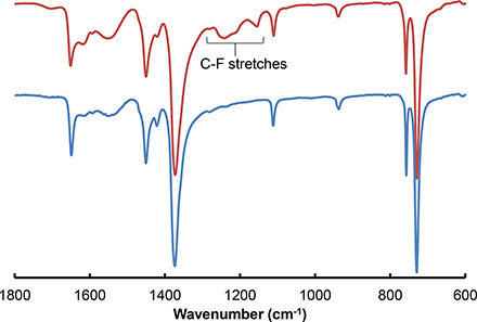 Figure 2. ATR-FTIR spectra of Cu-BTC (blue, bottom) and C2F6 plasma treated Cu-BTC (red, top). C-F stretches can be seen as IR bands between 1,300 and 1,140 cm-1.
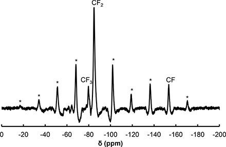 Figure 320. F MAS NMR spectra of C2F6 plasma treated Cu-BTC. Spinning side bands are labeled with an asterisk (*).
The Cu-BTC and C2F6 plasma treated Cu-BTC samples were rapidly aged at 45 °C and 100% RH for three days. The x-ray diffraction (XRD) patterns (Figure 4) show a near complete change in the structure of the untreated sample; however, the plasma treated sample shows minimal changes in the structure. The results are indicative of enhanced structural stability even under harsh humidity conditions. Analyses of the enhanced stability of Cu-BTC treated with perfluoroalkane plasmas are described in depth elsewhere14.
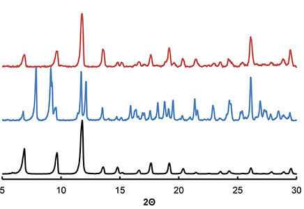 Figure 4. XRD patterns of Cu-BTC (black, bottom), Cu-BTC aged at 45 °C and 100% RH for 3 days (blue, middle), and C2F6 plasma treated Cu-BTC aged at 45 °C and 100% RH for 3 days (red, top).
A schematic of the device used for microbreakthrough analysis can be found in Figure 5. Microbreakthrough testing of aged Cu-BTC and C2F6 treated Cu-BTC samples for NH3 at a concentration of 2,000 mg/m3 are presented in Figure 6. Integration above the breakthrough curves yields capacities of 1.1 mmol of ammonia/g of Cu-BTC and 5.3 mmol of ammonia/g of C2F6 plasma treated Cu-BTC. The enhanced ammonia uptake of the plasma treated Cu-BTC sample after aging is due to the retention of the original Cu-BTC crystal structure, when compared to the aged Cu-BTC sample.
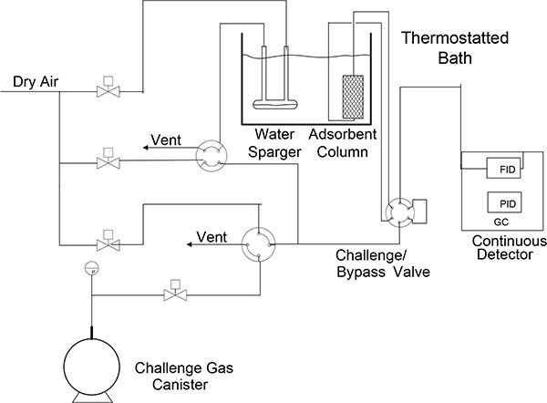 Figure 5. Schematic of microbreakthrough apparatus used for the ammonia breakthrough analysis of Cu-BTC samples. Figure reused with permission from reference 13.
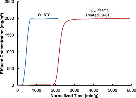 Figure 6. Ammonia breakthrough curves of Cu-BTC (blue) and C2F6 plasma treated Cu-BTC (red) showing the measured effluent concentration with relation to breakthrough time normalized by the mass of sample used.
Discussion
The synthesis of Cu-BTC, as in most MOFs, can be heavily dependent on the ratio of reactants used and the temperature the synthesis is carried out at. Varying the temperature or solvent used in synthesis has been shown to produce different morphologies of a MOF structure20. Therefore it is of strong importance to follow the procedure set forth in the literature for any MOF being synthesized. Furthermore, one should consider the reactants, solvents, and synthesis conditions when choosing a vessel in which to conduct the synthesis. MOFs can range in size from one material to the next; however Cu-BTC has very fine crystals on the order of 10 μm. The filter paper selected for the filtration steps should be adequate to recover crystals as small as 2.5 μm to maximize the yield, the vacuum filtration step may proceed slowly with such fine filter paper. Furthermore, during the activation step it is important to raise the temperature gradually to 170 °C, raising the temperature too rapidly has the potential to result in destruction of the MOF's microporous structure or cracking of the crystals.
The PECVD of perfluoroalkanes has been shown to enhance the water stability of MOFs that are otherwise prone to water degradation14. However, there are many intricacies when working with PECVD instruments. There is potential in any perfluoroalkane plasma treatment to form hydrogen fluoride, or other corrosive gases, and special care must be taken to protect the user and the instrument to these harmful species. All tubing, valves, mass flow controllers and connections need to be made of stainless steel or other corrosion resistant material; the vacuum pump must be compatible with corrosive gases; and all seals protecting the user from the instrument must be inspected regularly. Furthermore, there are hazards related to the RF generator including the ability to stop watches, the potential for erasing magnetic media, and no person with a pacemaker shall approach the plasma apparatus while it is running. Cleaning of the plasma apparatus regularly by running an oxygen plasma is necessary to remove any films that may form in the plasma chamber from previous experiments. An air plasma at 50 W should glow a bright pink color.
The treatment of powders via PECVD can be much different from treating flat wafers or other materials. In order to ensure a homogeneous treatment, the powder must be dispersed throughout a rotating glass bottle. For powders that have low density or are very fine particles, a permeable top needs to be placed on the glass bottle to ensure that when a vacuum is applied, the powder remains in the bottle. Porous materials, such as MOFs, typically physisorb water regularly from the atmosphere. This makes it important to apply a vacuum for a sufficient time before introducing the perfluoroalkane gas and lighting the plasma to ensure the MOF surface is reacting only with perfluoroalkane species. Cu-BTC has a colorimetric change from light-blue (hydrated) to deep purple (dehydrated) that can be used to indicate when the physisorbed water has been completely removed. It is important to determine for the microporous material-perfluoroalkane gas system a treatment process that is ideal, factors such as amount of material, pressure of perfluoroalkane gas, plasma power, and treatment time all have an effect on the overall outcome of the process. For instance, an increase in the amount material being treated requires an increase in the treatment to achieve similar results. Furthermore, an increase in the plasma power creates more perfluoroalkane radicals and can result in a faster deposition and/or different species being formed on the material21.
The theory behind microbreakthrough analysis has been well explained in the literature2. Special care needs to be taken when loading a sample into the glass tube. With only 10-15 mg of sample being loaded into the tube one must be careful to be very accurate in weighing, including not introducing any contaminant material and to handle the sample tube with gloves. To avoid powder samples being blown around the tube the flow must be from top to bottom. The dynamic loading can be calculated by integration over the breakthrough curve, the loading will vary with sorbate concentration and temperature. With respect to measuring sorbent capacities with an adsorption isotherm, the breakthrough technique only allows the determination of sorbate loading at a single concentration per experiment, representing a single point on an isotherm. However, the breakthrough technique more closely mimics actual filtration type applications.
The PECVD of microporous materials with perfluoralkanes opens up possibilities in many areas. We have shown how treating the surfaces with fluorocarbons can alter the wetting properties and hydrostability of MOFs. Furthermore this technique can be used to alter the adsorption properties of microporous materials, as the surfaces of the perfluoroalkane plasma treated material have different functional groups than the untreated material. This technique can be applied to a variety of other microporous materials, as well as extended to a variety of other precursor gases.
Disclosures
The authors declare that they have no competing financial interests.
Acknowledgments
The authors thank the Defense Threat Reduction Agency for funding under project number BA07PRO104, Martin Smith, Corrine Stone, and Colin Willis of the Defence Science and Technology Laboratory (DSTL) for their expertise in low pressure plasma technology, and Matthew Browe and Wesley Gordon of the Edgewood Chemical Biological Center (ECBC) for microbreakthrough testing and contact angle measurements, respectively.
References
- Montoro C, et al. Capture of Nerve Agents and Mustard Gas Analogues by Hydrophobic Robust MOF-5 Type Metal-Organic Frameworks. J. Am. Chem. Soc. 2011;133:11888–11891. doi: 10.1021/ja2042113. [DOI] [PubMed] [Google Scholar]
- Glover TG, Peterson GW, Schindler BJ, Britt D, Yaghi O. MOF-74 building unit has a direct impact on toxic gas adsorption. Chem. Eng. Sci. 2011;66:163–170. [Google Scholar]
- Britt D, Tranchemontagne D, Yaghi OM. Metal-organic frameworks with high capacity and selectivity for harmful gases. Proc. Natl. Acad. Sci. U.S.A. 2008;105:11623–11627. doi: 10.1073/pnas.0804900105. [DOI] [PMC free article] [PubMed] [Google Scholar]
- Peterson GW, et al. Ammonia Vapor Removal by Cu(3)(BTC)(2) and Its Characterization by MAS. NMR. J. Phys. Chem. Nanomater. Interfaces. 2009;113(3):13906–13917. doi: 10.1021/jp902736z. [DOI] [PMC free article] [PubMed] [Google Scholar]
- Gul-E-Noor F, et al. Effects of varying water adsorption on a Cu(3)(BTC)(2) metal-organic framework (MOF) as studied by (1)H and (13)C solid-state NMR spectroscopy. Phys. Chem. Chem. Phys. 2011;13(3):7783–7788. doi: 10.1039/c0cp02848g. [DOI] [PubMed] [Google Scholar]
- DeCoste JB, et al. The effect of water adsorption on the structure of the carboxylate containing metal-organic frameworks Cu-BTC, Mg-MOF-74, and UiO-66. J. Mater. Chem. 2013.
- Küsgens P, et al. Characterization of metal-organic frameworks by water adsorption. Microporous and Mesoporous Mater. 2009;120:325–330. [Google Scholar]
- Cavka JH, et al. A New Zirconium Inorganic Building Brick Forming Metal Organic Frameworks with Exceptional Stability. J. Am. Chem. Soc. 2008;130:13850–13851. doi: 10.1021/ja8057953. [DOI] [PubMed] [Google Scholar]
- DeCoste JB, et al. Stability and degradation mechanisms of metal-organic frameworks containing the Zr6O4(OH)4 secary building unit. J. Mater. Chem. A. 2013;1:5642–5650. [Google Scholar]
- Yang SJ, Park CR. Preparation of Highly Moisture-Resistant Black-Colored Metal Organic Frameworks. Adv. Mater. 2012;24:4010–4013. doi: 10.1002/adma.201200790. [DOI] [PubMed] [Google Scholar]
- Li H, et al. Enhanced Hydrostability in Ni-Doped MOF-5. Inorg. Chem. 2012;51:9200–9207. doi: 10.1021/ic3002898. [DOI] [PubMed] [Google Scholar]
- Jasuja H, Huang Y-g, Walton KS. Adjusting the Stability of Metal - Organic Frameworks under Humid Conditions by Ligand Functionalization. Langmuir. 2012;28:16874–16880. doi: 10.1021/la304151r. [DOI] [PubMed] [Google Scholar]
- Jasuja H, Burtch NC, Huang Y-g, Cai Y, Walton KS. Kinetic Water Stability of an Isostructural Family of Zinc-Based Pillared Metal - Organic Frameworks. Langmuir. 2012;29:633–642. doi: 10.1021/la304204k. [DOI] [PubMed] [Google Scholar]
- Decoste JB, Peterson GW, Smith MW, Stone CA, Willis CR. Enhanced Stability of Cu-BTC MOF via Perfluorohexane Plasma-Enhanced Chemical Vapor Deposition. J. Am. Chem. Soc. 2012;134:1486–1489. doi: 10.1021/ja211182m. [DOI] [PubMed] [Google Scholar]
- Bradley RH, Smith MW, Andreu A, Falco M. Surface studies of novel hydrophobic active carbons. Appl. Surf. Sci. 2011;257:2912–2919. [Google Scholar]
- Poire E, et al. Modification of active carbon by hydrophobic plasma plymers. Plasma Deposition of Polymeric Thin Films. 1994;54:185–196. [Google Scholar]
- Hozumi A, Takai O. Preparation of ultra water-repellent films by microwave plasma-enhanced CVD. Thin Solid Films. 1997;303(97):222–225. [Google Scholar]
- Dolbier WR. Guide to Fluorine NMR for Organic Chemists. John Wiley & Sons, Inc; 2009. [Google Scholar]
- Maricq MM, Waugh JS. NMR IN ROTATING SOLIDS. J. Chem. Phys. 1979;70:3300–3316. [Google Scholar]
- Kim M, Cahill JF, Su Y, Prather KA, Cohen SM. Postsynthetic ligand exchange as a route to functionalization of 'inert' metal-organic frameworks. Chem. Sci. 2012;3:126–130. [Google Scholar]
- d'Agostino R, et al. Advanced Plasma Technology. Wiley-VCH; 2008. [Google Scholar]
- DeCoste JB, et al. The effect of water adsorption on the structure of the carboxylate containing metal-organic frameworks Cu-BTC, Mg-MOF-74, and UiO-66. J. Mater. Chem. A. 2013.


