Abstract
In this paper we evaluate the accuracy of warping of neuro-images using brain deformation predicted by means of a patient-specific biomechanical model against registration using a BSpline-based free form deformation algorithm. Unlike the Bspline algorithm, biomechanics-based registration does not require an intra-operative MR image which is very expensive and cumbersome to acquire. Only sparse intra-operative data on the brain surface is sufficient to compute deformation for the whole brain. In this contribution the deformation fields obtained from both methods are qualitatively compared and overlaps of Canny edges extracted from the images are examined. We define an edge based Hausdorff distance metric to quantitatively evaluate the accuracy of registration for these two algorithms. The qualitative and quantitative evaluations indicate that our biomechanics-based registration algorithm, despite using much less input data, has at least as high registration accuracy as that of the BSpline algorithm.
Keywords: Brain, Non-rigid registration, Intra-operative MRI, Biomechanics, Edge detection, Hausdorff distance, Cerebral gliomas
1. INTRODUCTION
A novel partnership between surgeons and machines, made possible by advances in computing and engineering technology, could overcome many of the limitations of traditional surgery. By extending the surgeons’ ability to plan and carry out surgical interventions more accurately and with less trauma, Computer-Integrated Surgery (CIS) systems could help to improve clinical outcomes and the efficiency of health care delivery. CIS systems could have a similar impact on surgery to that long since realized in Computer-Integrated Manufacturing (CIM).30
Our overall objective is to significantly improve the efficacy and efficiency of image-guided neurosurgery for brain tumors by incorporating realistic computation of brain deformations, based on a fully non-linear biomechanical model, in a system to enhance intra-operative visualization, navigation and monitoring. The system will create an augmented reality visualization of the intra-operative configuration of the patient’s brain merged with high resolution pre-operative imaging data, including functional magnetic resonance imaging and diffusion tensor imaging, in order to better localize the tumor and critical healthy tissues.
In this paper we are especially interested in image-guided surgery of cerebral gliomas. Neurosurgical resection is the primary therapeutic intervention in their treatment.2 Near-total surgical removal is difficult due to the uncertainty in visual distinction of gliomatous tissue from adjacent healthy brain tissue. More complete tumor removal can be achieved through image-guided neurosurgery that uses intra-operative MRIs for improved visualization.46 The efficiency of intra-operative visualization and monitoring can be significantly improved by fusing high resolution pre-operative imaging data with the intra-operative configuration of the patient’s brain. This can be achieved by updating the pre-operative image to the current intra-operative configuration of the brain through registration. However, brain shift occurs during craniotomy (due to several factors including the loss of cerebrospinal fluid (CSF), changing pressure balances due to the impact of physiological factors and the effect of anesthetics, and mechanical effects such as the impact of gravity on the brain tissue) and hence should be accounted for while registering the images.
Intra-operative MRI scanners are very expensive and often cumbersome. Hardware limitations of these scanners make it infeasible to achieve frequent whole brain imaging during surgery. The pre-operative MRI must be updated frequently during the course of the surgical intervention as the brain is changing. An alternative approach is to acquire very rapid sparse intra-operative data and predict the deformation for the whole brain. To achieve this we developed a suite of algorithms based on brain tissue biomechanics for real-time estimation of the whole brain deformation from sparse intra-operative data.18, 20, 21
The aim of this paper is to demonstrate that our new algorithms, due to their utilization of fundamental physics of brain deformation, and their efficient realization in software, should enable at least as accurate registration of high quality pre-operative images onto the intra-operative position of the brain, as is now possible with intra-operative MRI and state-of-the-art non-rigid registration algorithm. We compare the accuracy of registration results obtained from two algorithms – (1) biomechanics-based Total Lagrangian Explicit Dynamics (TLED) suite of algorithms18, 20, 21, that uses only the intra-operative position of the exposed surface of the brain; and (2) BSpline-based free form deformation (FFD) algorithm37 as implemented in 3D Slicer (www.slicer.org), that uses an intra-operative MRI as a target image. We present results for thirteen neurosurgery cases†, sourced from a large retrospective database of glioma patients available at the Children’s Hospital in Boston. These cases were documented with carefully acquired T1-weighted MRIs (resolution of 0.86×0.86×2.5 mm3) on a 0.5 T interventional scanner, and they represent different situations which may occur during surgery as characterized by tumors located in different parts of the brain. The intra-operative deformations for these thirteen cases ranged between 3 mm to 10 mm.
The accuracy of these algorithms is compared qualitatively by viewing and exploring the calculated deformation fields and overlap of edges detected from MRI images. In addition, the registration error for each algorithm is also estimated quantitatively by means of a novel edge-based Hausdorff distance measure.6
2. MATERIALS AND METHODS
2.1. Non-rigid pre-operative to intra-operative registration using the BSpline algorithm
Free form deformation (FFD) is a powerful tool for modeling 3D deformable objects and widely used in image morphing25 and scattered data interpolation.26, 38 The basic idea of FFD is to deform an object by manipulating the underlying grid of control points.37 In order to smoothly propagate the user-specified values at the control points throughout the domain of the image, a BSpline based FFD algorithm was proposed by Lee et al.26 The BSpline algorithm was later adapted by Rueckert et al.37 for non-rigid registration of medical images. Since then the BSpline algorithm has become one of the most widely used non-rigid registration algorithm for medical images.22-24, 36-39
Let us denote the domain of the image volume as Ω = {(x, y, z) | x ∈ [0, X), y ∈ [0,Y), z ∈ [0, Z)}. Let also denote Φ as a nx × ny × nz discrete grid of control points with uniform spacing δ, overlaid on the domain Ω. If φi,j,k is a control point on the lattice Φ at location (i, j, k), where {i, j, k} ∈ {[−1, nx +1], [−1, ny +1], [−1, nz +1]}, then, the deformation at any point (x, y, z) within Ω can be written as a 3D tensor product of the 1D cubic BSplines:37
| (1) |
where [x] represents the highest integer lower than x, , , , , , , and Bl represents the lth basis function of the BSpline,
| (2) |
The registration parameters are determined by optimizing a cost function consisting of a similarity criterion (for example mutual information), which measures the degree of alignment between the fixed and moving image, and a regularization term to obtain a smooth transformation,37
| (3) |
where λ is a weighting parameter that defines the trade-off between the alignment of images and the smoothness of transformation. IF and IM represent the intensities of the fixed and moving images. Cubic BSplines have compact support, therefore a change in a control point only affects the neighborhood of this control point. A large spacing of control points allows modeling of global non-rigid deformations, while a finer grid of control points allows modeling highly local deformations. The resolution of control point grid also determines the number of degrees of freedom of the transformation, and consequently, the computational complexity.
The basic components of an image-based registration algorithm8, used also by BSpline based methods, are presented in Fig. 1. The moving (pre-operative) image (M) is transformed using the chosen transformation T (in this case the displacements of control points) to obtain the transformed image T(M). The transformed image is then compared with the fixed (intra-operative) image (F) based on a chosen similarity measure S. This similarity metric is used by an optimizer to find the parameters of the transform that minimizes the difference between the moving and fixed image. Therefore an optimization loop is required, which changes the transform parameters to find the best agreement between the fixed and moving image.
FIGURE 1.

Basic components of a general image-based registration process.
In this paper we choose the robust, reliable and commonly used implementation of the BSpline algorithm in 3D Slicer (www.slicer.org). The use of this widely available implementation (over 68000 downloads of the latest version, Slicer 4) will facilitate evaluation of our results by other researchers. Below, the implementation of BSpline algorithm in 3D Slicer is described briefly. A number of factors influencing the registration results for image guided-neurosurgery are also discussed in the following subsection.
Estimation of probability densities
The most commonly used similarity measure in multi-modal non-rigid registration is mutual information. Calculation of mutual information between the fixed and the transformed moving image requires the values of the marginal and joint probability densities.3 These probability densities are usually not readily known; therefore they must be estimated from discrete image data. In 3D Slicer the probability densities are estimated using Parzen windows.41 In this scheme, the densities are constructed by taking limited number of intensity samples Si from the images and super-imposing a kernel function K centered on Si.
Implementation of similarity measure
The similarity measure used in 3D Slicer BSpline registration module is defined by Mattes et al.28 In this implementation, the joint and marginal probability densities are estimated from a set of intensity samples drawn from the images. A zero-order BSpline kernel is used to estimate the probability density function (PDF) of the fixed image intensities. On the other hand, a cubic BSpline kernel is used to estimate the moving image PDF.29
2.1.1 BSpline registration for image-guided neurosurgery
In the case of image-guided neurosurgery where the pre-operative image is required to be registered with the intra-operative (after craniotomy is performed) image, the Bspline registration algorithm faces a number of challenges. First of all, the large difference in intensities between the pre-operative and intra-operative MRI often influences the registration result. Intensity normalization between the source and target image is required to achieve decent registration results. Secondly, the presence of the skull in the craniotomy area of the pre-operative image makes the registration process difficult and can induce large error in the registration. In order to achieve good alignment the skull must be stripped from both the pre- and intra-operative images. In addition, selecting an appropriate set of parameters (density of control point grid, number of spatial samples and number of histogram bins) for a particular registration case requires substantial training and experience. Without performing proper intensity normalization and setting appropriate control point grid density, it is extremely difficult to obtain accurate results using a purely image-based, non-rigid registration algorithm such as BSpline. Therefore, to determine the effects of the intensity normalization steps and control point mesh density on the registration results, we conducted a parametric study of craniotomy-induced brain shift. The results of this parametric study are presented below.
Effect of control point mesh density
Fig. 2 shows the effect of control point mesh density on the registration result. In this figure the pre-operative and intra-operative contours are overlaid on an axial slice. As the control point mesh density is increased, the alignment of brain contours improves, however, the alignment of ventricle contours decreases. At a 20 × 20 × 20 control grid (Fig. 2c) the alignment of brain contours is very good, but the alignment of ventricles is poor. This confirms a well-known fact that unlike for biomechanical registration algorithms that use the principles of mechanics governing the organ deformation and require parameters with clear physical (measurable) meaning, optimization of the registration parameters of BSpline and other algorithms that rely solely on image processing techniques is numerically challenging. The BSpline registration using 20×20×20 regularization grid version has many more parameters than the one using 10×10×10 grid and tends to be more numerically unstable. Therefore, we used 10×10×10 grid to conduct registration of pre- and intra-operative MRIs for thirteen neurosurgical cases using the BSpline algorithm.
FIGURE 2.
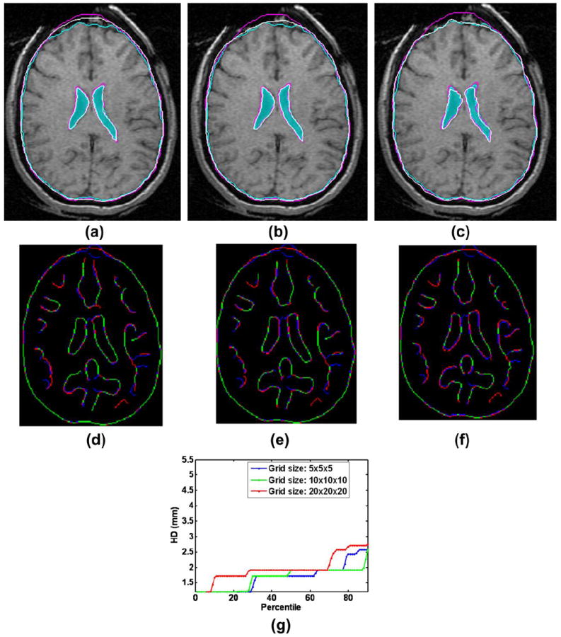
Effect of control point mesh density on registration result: (a) Mesh Density 5 × 5 × 5, (b) Mesh Density 10 × 10 × 10 and (c) Mesh Density 20 × 20 × 20. (d) – (f): Canny edges extracted from intra-operative and the registered pre-operative image slices overlaid on each other for three mesh densities. Red color represents the non-overlapping pixels of the intra-operative slice and blue color represents the non-overlapping pixels of the pre-operative slice. Green color represents the overlapping pixels. (g) Corresponding plots of edge-based Hausdorff distances at different percentiles. Detailed description of methods required to generate this plot is given in Section 2.3.2. All registration results were generated using skull-stripped brain volumes with 50000 spatial samples to calculate joint intensity histograms. The following color code is used for contours in (a) – (c): light blue shade – ventricles in the intra-operative image; light blue contour – outline of parenchyma in the intra-operative image; magenta contours – outlines of parenchyma and ventricles in the pre-operative image before registration; white contours - outlines of parenchyma and ventricles in the pre-operative image after registration.
Effect of intensity normalization
In the pre-processing step the intensity of the images was normalized through bias field correction followed by histogram equalization. The N4 algorithm43 was used for non-uniform bias field correction which assumes a Gaussian model for the bias field and uses a multi-resolution scheme for correction. Although intensity normalization does not affect the alignment of brain contours much, it significantly improves the alignment of the ventricle contours (Fig. 3b).
FIGURE 3.
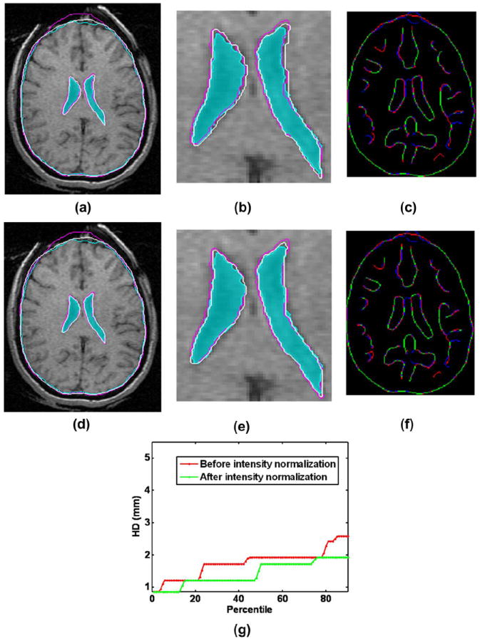
Effect of intensity normalization on the registration result: (a) Intra-operative and warped pre-operative contours obtained without intensity normalization overlaid on the intra-operative slice; (b) A zoomed-in view of the contour ventricles in (a); (c) Corresponding Canny edges extracted from intra-operative and the warped pre-operative image slices overlaid on each other; (d) Intra-operative and warped pre-operative contours obtained with intensity normalization overlaid on the intra-operative slice; (e) A zoomed-in view of the contour ventricles in (d); (f) Corresponding Canny edges extracted from intra-operative and the warped pre-operative image slices overlaid on each other; (g) Plots of edge-based Hausdorff distances at different percentiles before and after intensity normalization. Detailed description of methods required to generate this plot is given in Section 2.3.2. All registration results were generated using skull-stripped brain volumes with 50000 spatial samples to calculate joint intensity histograms. The following color code is used for contours in (a), (b), (d) and (e): light blue shade – ventricles in the intra-operative image; light blue contour – outline of parenchyma in the intra-operative image; magenta contours – outlines of parenchyma and ventricles in the pre-operative image before registration; white contours - outlines of parenchyma and ventricles in the pre-operative image after registration. Color code for edges: Red color represents the non-overlapping pixels of the intra-operative slice, blue color represents the non-overlapping pixels of the pre-operative slice and green color represents the overlapping pixels.
In order to produce registration results using the BSpline algorithm we estimated the marginal and joint probabilities using 50 histogram bins and 50000 spatial samples. Prior to registration all pre-operative/intra-operative image pairs were normalized using histogram equalization and N4 bias field correction. A 10×10×10 grid was used to obtain the transform. For such low density grid it is advantageous to set regularization parameter λ to zero.37,22
The relative performance of BSpline and biomechanics-based registration against rigid registration – a technique that is currently available to patients, is given in Fig. 4.
FIGURE 4.
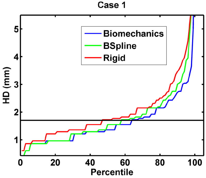
The plot of percentile edge-based Hausdorff distance between intra-operative and registered pre-operative images against the corresponding percentile of edges for axial slices showing relative accuracy of BSpline and biomechanics-based deformable registration methods as compared to rigid registration. Detailed description of methods required to generate this plot is given in Section 2.3.2.
2.2. Biomechanics-based prediction of deformations using only the information about the position of the exposed brain surface
Unlike the BSpline registration algorithm, biomechanics-based registration methods do not require an intra-operative image to update the pre-operative image (see Fig. 5). The pre-operative image is segmented first to extract the anatomical features of interest. Based on this segmentation (which can be acquired days before the surgery) a computational grid (mesh) is generated. A biomechanical model is defined further by incorporating boundary conditions (contact between the skull and the brain for example) and material properties for each tissue types. The model is completed by defining the loading conditions that are generally obtained from sparse intra-operative information (such as surface deformation in the craniotomy area). Once the model is constructed, a solver (finite element or meshless) is used to compute the transform, which is then applied to warp the pre-operative image. The warping procedure requires the mapping of points in the moving (pre-operative) image to the new locations in the transformed image. The intensity of the points in the transformed image is determined by interpolating intensities of the corresponding points in the moving image. In the following subsections the non-linear finite element modeling procedure proposed by Joldes et al.18 and Wittek et al.48 to predict the intra-operative brain shift is briefly described.
FIGURE 5.
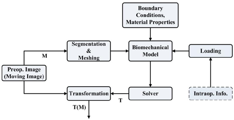
Registration process based on a biomechanical model.
2.2.1. Construction of finite element mesh for patient-specific brain models
A three dimensional (3D) surface model of each patient’s brain was created from segmented pre-operative magnetic resonance image (MRI). Following our previous studies on predicting craniotomy-induced deformations within the brain20, 21, 47-49, in this investigation, different material properties were assigned to the parenchyma, tumor and ventricles. Accordingly, to obtain the information for building the computational grids (finite element meshes), the parenchyma, tumor and ventricles were segmented using the region growing algorithm implemented in 3D slicer, followed by manual correction.
The meshes were constructed using low-order elements (linear tetrahedron or hexahedron) to meet the computation time requirement. To prevent volumetric locking the tetrahedral elements with average nodal pressure (ANP) formulation were used.17 The meshes were generated using IA-FEMesh7 and HyperMesh (commercial FE mesh generator by Altair of Troy, MI, USA). A typical mesh (Case 1) is shown in Fig. 6. This mesh consists of 14,447 hexahedral elements, 13563 tetrahedral elements and 18806 nodes. Each node in the mesh has three degrees of freedom.
FIGURE 6.
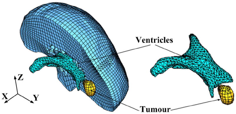
Typical example (Case 1) of a patient-specific mesh built for this study.
2.2.2. Displacement loading
The models were loaded by prescribing displacements on the exposed part (due to craniotomy) of the brain surface. As this requires only replacing the brain-skull contact boundary condition with prescribed displacements, no mesh modification is required at this stage. At first the pre-operative and intra-operative coordinate systems were aligned by rigid registration. Then the displacements at the mesh nodes located in the craniotomy region were estimated with the interpolation algorithm we described in a previous publication.19
As explained in our papers34, 47, for problems where loading is prescribed as forced motion of boundaries, the unknown deformation field within the domain depends very weakly on the mechanical properties of the continuum. This feature is of a great advantage in biomechanical modeling where there are always uncertainties in patient-specific properties of tissues.33
2.2.3. Boundary conditions
The stiffness of the skull is several orders of magnitude higher than that of the brain tissue. Therefore, in order to define the boundary conditions for the unexposed nodes of the brain mesh, a contact interface14 was defined between the rigid skull model and the deformable brain. The interaction was formulated as a finite sliding, frictionless contact between the brain and the skull. The effects of assumptions regarding the brain boundary conditions on the results of prediction of deformations within the brain have been analyzed and discussed49, 50 before.
2.2.4. Mechanical properties of the intracranial constituents
If geometric non-linearity is considered47, the predicted deformation field within the brain is only weakly affected by the constitutive model of the brain tissue. Therefore, for simplicity a hyper-elastic Neo-Hookean model was used.15 The Young’s modulus of 3000 Pa was selected for parenchyma.31 The Young’s modulus for tumor was assigned a value two times larger than that for the parenchyma, keeping it consistent with the experimental data of Sinkus et al.40 As the brain tissue is almost incompressible, a Poisson’s ratio of 0.49 was chosen for the parenchyma and tumor.49 The ventricles were assigned properties of a very soft compressible elastic solid with a Young’s modulus of 10 Pa and Poisson’s ratio of 0.1.49
2.2.5. Solution algorithm
A suite of efficient algorithms for integrating the equations of solid mechanics and its implementation on Graphics Processing Unit for real-time applications are described in detail by Joldes et al.18, 20 The computational efficiency of this algorithm is achieved by using - 1) Total Lagrangian (TL) formulation32 for updating the calculated variables; and 2) Explicit Integration in the time domain combined with mass proportional damping. In the TL formulation, all the calculated variables (such as displacements and strains) are referred to the original configuration of the analyzed continuum.16 The decisive advantage of this formulation is that all derivatives with respect to spatial coordinates can be pre-computed. The Total Lagrangian formulation also leads to a simplification of material law implementation as these material models can be easily described using the deformation gradient.18
The integration of equilibrium equations in the time domain was performed using an explicit method. When a diagonal (lumped) mass matrix is used the discretised equations are decoupled. Therefore, no matrix inversions and iterations are required when solving nonlinear problems. Application of explicit time integration scheme reduces the time required to compute the brain deformations by two orders of magnitude in comparison to implicit integration typically used in commercial finite element codes like ABAQUS.1 This algorithm is also implemented on GPU (NVIDIA Tesla C1060 installed on a PC with Intel Core2 Quad CPU) for real-time computation20 so that the entire model solution takes less than four seconds on commodity hardware.
The application of the biomechanics-based approach does not require any parameter tuning, and the results presented in Section 3 demonstrate the predictive (rather than explanatory) power of this method.
2.3. Methods for evaluation of registration accuracy
2.3.1. Qualitative evaluation
Deformation field
The physical plausibility of the registration results are verified by examining the computed displacement vector at voxels of the pre-operative image domain. The deformations are computed at voxel centers only for a region of interest near the tumour.
Overlap of edges
To obtain a qualitative assessment of the degree of alignment after registration, one must examine the overlap of corresponding anatomical features of the intra-operative and registered pre-operative image. For this purpose, tumors and ventricles in both registered pre-operative and intra-operative images can be segmented and their surfaces can be compared.48 Image segmentation is time consuming, subjective, not fully automated and not suitable for comparing a large number of image pairs.5 Therefore in this paper Canny edges4 are used as feature points. Edges are regarded as useful and easily recognizable features, and they can be detected using techniques that are automated and fast. Canny edges obtained from the intra-operative and registered pre-operative image slices are labeled in different colors and overlaid (as shown in Section 3.1.2).
2.3.2. Quantitative evaluation
Edge-based Hausdorff distance
The Hausdorff distance is a popular measure to calculate similarities between two images.9 It is defined based on two sets of feature points, A and B. We begin with a definition of the traditional point-based Hausdorff distance (HD) between two intensity images I and J. Let I and J be the binary edge images derived from I and J respectively, and A = {a1, ⋯, an} and B = {b1, ⋯, bn} are the set of non-zero points corresponding to the non-zero pixels on the edge images. The directed distance between them h(A, B) is defined as the maximum distance from any of the points in the first set to the closest point in the second one:
| (4) |
| (5) |
The HD between the two sets H(A, B) is defined as the maximum of these two directed distances:
| (6) |
Several improvements of the directed distance have been proposed.52 One of them is the percentile Hausdorff distance, which is very useful for identifying outliers. The percentile directed distance is defined as:
| (7) |
where P is the Pth percentile of .
The above definition of Hausdorff distance sets an upper-limit on the dissimilarities between two images. It implies that the value indicated by Eq.6 generally comes from a single pair of points. The other point pairs have a distance less than or equal to that value. Such a measure is very useful for template based image matching. However, while measuring the misalignments between two medical images, it is desirable to calculate the distance between local features (in the case of brain MRI considered here, the automatically detected Canny edges) in two images that correspond to each other. To calculate such a distance we define the edge-based Hausdorff distance.
We define directed distance between two sets of edges as
| (8) |
where and are two sets of edges.
The quantity in Eq. 8 is nothing but the point based Hausdorff distance between two point sets M = {m1, ⋯, mp} and T = {t1, ⋯, tq} representing edges and respectively,
| (9) |
Now the edge-based Hausdorff Distance is defined as
| (10) |
Similar to the percentile point-based Hausdorff distance, one can construct a percentile edge-based Hausdorff distance:
| (11) |
This percentile edge-based Hausdorff distance (Eq. 11) is not only useful for removing outlier edge-pairs, but also can be interpreted in a different way. The Pth percentile Hausdorff distance, ‘D’, between two images means that ‘P’ percent of total edge pairs have a Hausdorff distance below D. Therefore, instead of reporting only one Hausdorff distance value (using Eq.10), Eq.11 can be used to report Hausdorff distance values for different percentiles. A plot of the Hausdorff distance values at different percentiles (see Section 3.2) immediately reveals the percent of edges that have misalignments below an acceptable error.
In order to obtain these curves of Hausdorff distance values at different percentiles, each pre-operative/intra-operative image pair was cropped into a common region-of-interest (ROI) which encloses the tumor. These ROI sub-volumes were then super-sampled (0.5 mm × 0.5 mm × 0.5 mm) to obtain isotropic voxels. This was done to improve the precision of Canny edge detection4 used in the registration accuracy evaluation process. The edge-based Hausdorff distance (HD) was used to calculate the misalignment between slices along both axial and sagittal directions. The directed distances for all edge pairs (see Eq. 8) were recorded and the edge-based Hausdorff distance values at different percentiles of directed distances were plotted.
Pre-processing - Outlier Removal
Although edges are supposed to be representative of consistent features present in two separate images, outliers are very common if the intensity ranges of the images are different. It is often the case in multi-modal image registration. Therefore, pre-processing of the extracted edges is required to remove outliers before the edge-based Hausdorff distance could be calculated. We used a pre-processing step called the “round-trip consistency” procedure6 that removes the pixels of one image that do not correspond to the other image.
3. RESULTS
3.1. Qualitative evaluation of registration results
3.1.1. Deformation field
The deformation fields predicted by the biomechanical model and obtained from the BSpline transform are compared in Fig. 7. These deformation fields are three dimensional. However, for clarity, only arrows representing 2D vectors (x and y components of displacement) are shown overlaid on undeformed pre-operative slices. Each of these arrows represents the displacement of a voxel of the pre-operative image domain. In general the displacement fields calculated by the BSpline registration algorithm are similar to the predicted displacements by the biomechanical model at the outer surface of the brain, but in the interior of the brain volume the displacement vectors differ in both magnitude and direction. In three of the cases (cases 8, 11 and 12) the difference in the displacement fields is smaller compared to the other cases.
FIGURE 7.
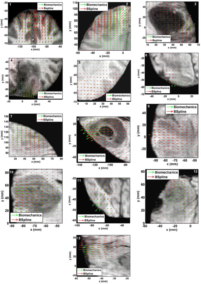
The predicted deformation fields overlaid on an axial slice of pre-operative image. An arrow represents a 2D vector consisting of the x (R-L) and y (A-P) components of displacement at a voxel centre. Green arrows: deformation field predicted by the biomechanical model. Red arrows: deformation field calculated by the BSpline algorithm. The number on each image denotes a particular neurosurgery case.
3.1.2. Overlap of Canny edges
From Fig. 8 we can see that misalignment between the edges detected from the intra-operative images and the edges from the pre-operative images updated to the intra-operative brain geometry are much lower for the biomechanics-based warping than for BSpline registration. The edges obtained from the images warped with both registration algorithms have higher similarity for cases 8, 11 and 12 than the other cases. This is due to the fact that the deformation fields predicted using the biomechanical model and BSpline registration have higher similarity for these three cases. For instance, large misalignments between the edges obtained from the intra-operative image and edges from the pre-operative image registered using BSpline algorithm can be observed for Case 2. For this case there was a large intra-operative brain shift (8mm) and the deformation field obtained using BSpline algorithm significantly differs from deformation predicted using the biomechanical model. This is an indication that the biomechanics-based warping may perform more reliably than the BSpline registration algorithm if large deformations are involved.
FIGURE 8.
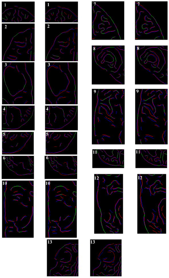
Canny edges extracted from intra-operative and the registered pre-operative image slices overlaid on each other. Red colour represents the non-overlapping pixels of the intra-operative slice and blue colour represents the non-overlapping pixels of the pre-operative slice. Green colour represents the overlapping pixels. The number on each image denotes a particular neurosurgery case. For each case, the left image shows edges for the biomechanics-based warping and the right image shows edges for the BSpline-based registration.
3.2. Quantitative evaluation of registration results
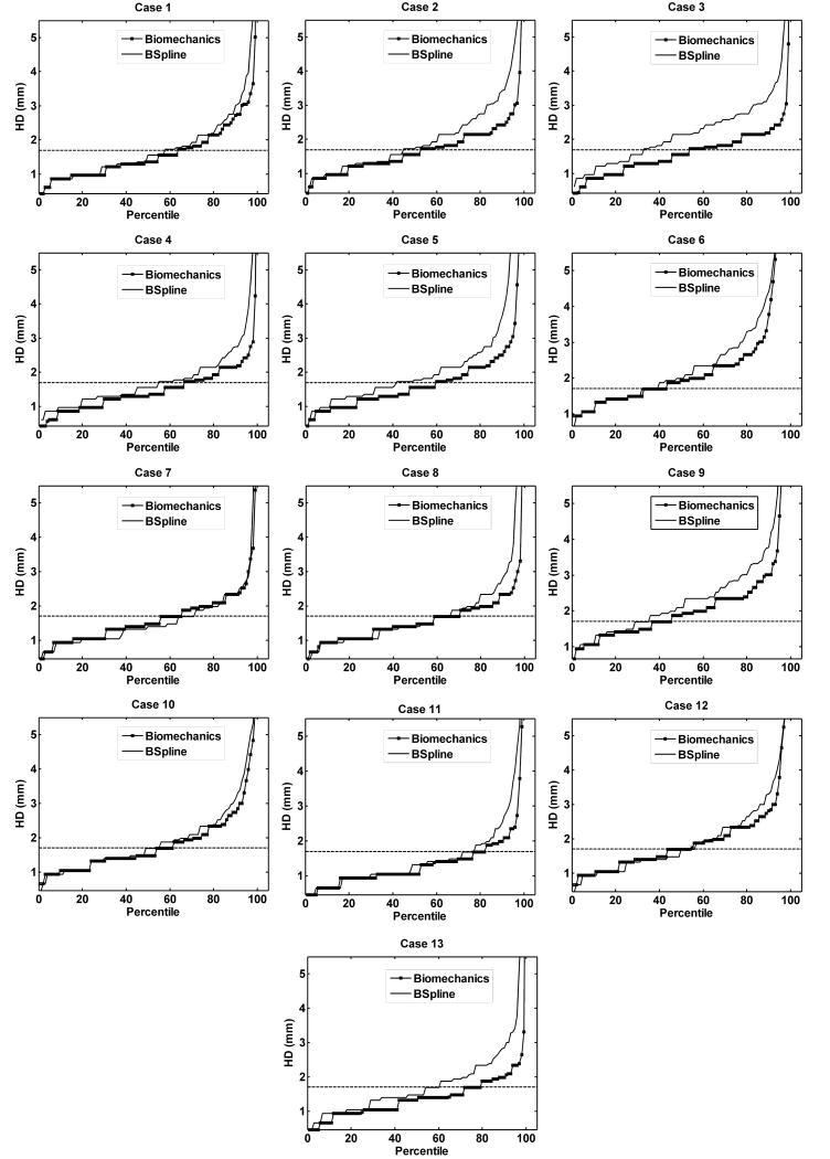
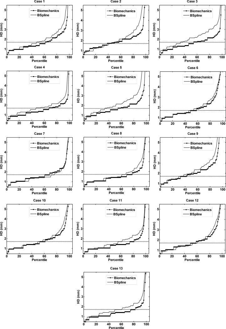
The plot of percentile edge-based Hausdorff distance (HD) versus the corresponding percentile provides an estimation of the percentage of edges that were successfully registered in the registration process. As the accuracy of edge detection is limited by the image resolution, an alignment error smaller than two times the original in-plane resolution of the intra-operative image (which is 0.86 mm for the thirteen cases considered) is difficult to avoid.46 Hence, for the thirteen clinical cases analyzed here, we considered any edge pair having HD value less than 1.7 mm to be successfully registered. This choice is consistent with the fact that it is generally considered that manual neurosurgery has an accuracy of no better than 1 mm.35, 46 It is obvious from Fig. 9 and 10 that biomechanical warping was able to successfully register more edges than the BSpline registration for all thirteen cases.
FIGURE 9.
The plot of Hausdorff distance between intra-operative and registered pre-operative images against the percentile of edges for axial slices. The horizontal line is the 1.7 mm mark.
FIGURE 10.
The plot of Hausdorff distance between intra-operative and registered pre-operative images against the percentile of edges for sagittal slices. The horizontal line is the 1.7 mm mark.
The percentage of edges successfully registered by the two registration algorithms (i.e. warping using the biomechanical model and the BSpline registration) for each analyzed case is listed in Table 1. The percentage of successfully registered edges is slightly higher for image warping using biomechanical model than that for BSpline registration (with an exception for Case 7). It can be noted that the Hausdorff distance values in the sagittal plane are generally higher than those in the axial plane. This is most likely caused by an interpolation artifact (due to the poor resolution in the sagittal plane) introduced in the re-slicing process.
Table 1.
Percentage of edges successfully registered for thirteen patient specific cases.
| Case | Percentage of edges successfully registered | |||
|---|---|---|---|---|
| Axial Slices | Sagittal Slices | |||
| Biomechanics | BSpline | Biomechanics | BSpline | |
| ‘1’ | 70 | 63 | 61 | 47 |
| ‘2’ | 56 | 45 | 38 | 41 |
| ‘3’ | 54 | 29 | 54 | 33 |
| ‘4’ | 66 | 54 | 67 | 46 |
| ‘5’ | 58 | 45 | 54 | 33 |
| ‘6’ | 59 | 51 | 58 | 53 |
| ‘7’ | 75 | 81 | 61 | 76 |
| ‘8’ | 75 | 70 | 69 | 65 |
| ‘9’ | 52 | 43 | 52 | 46 |
| ‘10’ | 61 | 55 | 61 | 57 |
| ‘11’ | 82 | 77 | 81 | 62 |
| ‘12’ | 63 | 59 | 58 | 60 |
| ‘13’ | 81 | 67 | 82 | 62 |
| Average | 65.54 | 56.85 | 61.23 | 52.38 |
For all thirteen cases, the percentile edge-based HD curves tend to rise steeply around 90th percentile. Hence, it can be safely assumed that most edge pairs that lie between 91 and 100 percentile do not have any correspondence (possible outliers). The 90th percentile HD values for all cases are listed in Table 2.
Table 2.
90th percentile Hausdorff distance values (mm) for thirteen patient-specific cases.
| Case | Non-rigid registration algorithm | |||
|---|---|---|---|---|
| Axial Slices | Sagittal Slices | |||
| Biomechanics | BSpline | Biomechanics | BSpline | |
| ‘1’ | 2.43 | 2.75 | 2.75 | 3.54 |
| ‘2’ | 2.43 | 3.36 | 2.72 | 3.87 |
| ‘3’ | 2.19 | 3.10 | 2.43 | 3.44 |
| ‘4’ | 2.15 | 2.75 | 2.15 | 2.61 |
| ‘5’ | 2.58 | 3.36 | 2.58 | 3.87 |
| ‘6’ | 3.14 | 3.44 | 3.32 | 3.75 |
| ‘7’ | 2.34 | 2.15 | 2.39 | 2.34 |
| ‘8’ | 2.34 | 2.73 | 2.34 | 2.96 |
| ‘9’ | 3.00 | 4.03 | 3.66 | 4.32 |
| ‘10’ | 2.73 | 3.14 | 2.85 | 3.41 |
| ‘11’ | 1.99 | 2.52 | 2.10 | 2.65 |
| ‘12’ | 2.81 | 3.28 | 3.14 | 3.78 |
| ‘13’ | 1.99 | 2.85 | 1.99 | 2.65 |
| Average | 2.47 | 3.03 | 2.65 | 3.32 |
4. DISCUSSION
From the results presented in Section 3, it is evident that the application of intra-operative deformation predicted a using patient-specific biomechanical model18, 20, 48 to warp pre-operative images ensures at least as high registration accuracy as that of 3D Slicer’s BSpline registration module. Biomechanical models are especially effective in neurosurgery cases where intra-operative brain shift is large (Case 2 for instance). Another distinctive advantage of using the biomechanical model is that it does not need the intra-operative image at all to compute deformation. Only the displacement of a limited number of points on the exposed intra-operative brain surface in the craniotomy area is required. For image warping using the intra-operative brain deformation predicted using a patient-specific biomechanical model, the required number of intra-operative data points is reduced by four orders of magnitude compared to purely image-based registration, from about 106 to about 102. The most appealing and convenient way of acquiring the current, intra-operative position of the exposed surface of the brain, that we need to define the loading of our models, is the use of the tracking pointer tool available within the commonly-used Medtronic’s Stealth neuronavigation system that enables the surgeon to select (by touching) a number of points on the brain surface (technical details are available online at http://www.na-mic.org/Wiki/index.php/Stealthlink_Protocol) and determine their positions in the images using software tools implemented in 3D Slicer.42, 44, 45 Stereo-vision using cameras or laser range scanners installed in an operating theatre are validated alternatives for capturing the displacements of the cortical surface. The examples include the studies by Ji et al.10, 11
Intra-operative MRIs, used in this study, are not necessary for aligning the patient’s intra-operative position with the pre-operative image. Rigid registration can be performed using e.g. the ExacTrac system12 available in BrainLAB (BrainLAB AG, Germany, www.brainlab.com) or Stealth neuronavigation system from Medtronic.
We chose the widely used BSpline implementation available in 3D Slicer. The purpose of this study is to show that state-of-the-art biomechanical registration algorithms (that require only very sparse information about the intra-operative brain geometry) can facilitate registration accuracy similar to that provided by commonly used algorithms that rely solely on image processing techniques (and therefore require intra-operative MRI). The choice of the robust and commonly used implementation of BSpline algorithm in 3D Slicer fits this purpose very well. Moreover, the use of widely available and reliable implementation facilitates the evaluation of our results by other researchers. To strengthen the conclusions of this work an alternative implementation and alternative algorithms for image-based alignment should be evaluated in future work.
The construction of the finite element mesh requires segmentation of pre-operative neuroimages. The difficulties associated with segmentation of tumors when building finite element meshes for biomechanical models of the brain were discussed in our previous study.48 It is worth noting, however, that the analysis of sensitivity of computed brain deformations to the complexity of the biomechanical models used27 demonstrates that even assigning exactly the same material properties to the tumor as to the rest of the parenchyma, therefore avoiding tumor segmentation entirely, leads to only minimal (and for practical purposes negligible) deterioration in the accuracy of predicted displacements.
This strongly suggests that accuracy of prediction of the intra-operative deformations within the brain obtained using our biomechanical models are, for practical purposes, insensitive to segmentation errors. This is reinforced by our recent results51 indicating that the accuracy of such predictions only slightly (approximately 0.1 mm) decreases if, in the process of building computational grids and assigning mechanical properties for the models, segmentation is replaced with fuzzy tissue classification (that does not provide clearly defined boundaries between different anatomical structure within the organ and tends to introduce local tissue misclassification).
Modeling of resection is a very challenging problem of computational biomechanics due to discontinuities and large local strains caused by tissue removal/separation. Such discontinuities alter the topology of finite element meshes while large local strains lead to mesh distortion and deterioration of the solution accuracy. To address these challenges, in our recent studies13 we proposed a meshless algorithm (in which the analysed continuum/body organ is discretised using a cloud of points) for surgical dissection simulation.
We believe that the results presented in this paper have the potential to significantly advance the way imaging is used to guide the surgery of brain tumors. Presently, our experience has demonstrated the great utility of intra-operative MRI in ensuring complete resection, particularly of low grade tumors. However, this often comes at the expense of significantly longer operating times, as well as being resource intense. For example, the decision to acquire a new volumetric image requires expertise from technologists, radiologists, and others. At hospitals that have at their disposal the intra-operative MRI, the ability to know when imaging is needed, as well as the potential reduction in the number of imaging acquisitions promises to make intra-operative MRI a much more effective and efficient technique.
Even more importantly, we believe that the use of comprehensive biomechanical computations in the operating theatre may present a viable and economical alternative to intra-operative MRI. The brain deformation modeling algorithms proposed here may lead the way towards allowing updated representations of the brain position even without intra-operative MRI and therefore bring the success of image-guided neurosurgery to a much wider population of sufferers.
Acknowledgments
A. Mostayed and R.R. Garlapati are recipients of Scholarship for International Research Fees SIRF. A. Roy is a recipient of University Postgraduate Award UPA scholarship. A. Mostayed, R.R. Garlapati and A. Roy gratefully acknowledge the financial support of The University of Western Australia. The financial support of National Health and Medical Research Council (Grant No. APP1006031) is gratefully acknowledged. This investigation was also supported in part by NIH grants R01 EB008015 and R01 LM010033, and by a research grant from the Children’s Hospital Boston Translational Research Program. In addition, the authors also gratefully acknowledge the financial support of Neuroimage Analysis Center (NIH P41 EB015902), National Center for Image Guided Therapy (NIH U41RR019703) and the National Alliance for Medical Image Computing (NAMIC), funded by the National Institutes of Health through the NIH Roadmap for Medical Research, Grant U54 EB005149. Information on the National Centers for Biomedical Computing can be obtained from http://nihroadmap.nih.gov/bioinformatics.
Footnotes
IRB approval was acquired for the use of the anonymised retrospective image database for this study.
References
- 1.ABAQUS. ABAQUS Theory Manual Version 5.2. Hibbit, Karlsson & Sorensen, Inc; 1998. [Google Scholar]
- 2.Black P. Management of malignant glioma: role of surgery in relation to multimodality therapy. J Neurovirol. 1998;4:227–236. doi: 10.3109/13550289809114522. [DOI] [PubMed] [Google Scholar]
- 3.Box GEP, Hunter WG, Hunter JS. An introduction to Design, Data Analysis, and Model Building. New York: John Wiley & Sons; 1978. Statistics for Experimenters. [Google Scholar]
- 4.Canny J. A computational approach to edge detection. IEEE Trans Pattern Anal Mach Intell. 1986;8:679–698. [PubMed] [Google Scholar]
- 5.Fedorov A, Billet E, Prastawa M, Gerig G, Radmanesh A, Warfield SK, Kikinis R, Chrisochoides N. Evaluation of Brain MRI Alignment with the Robust Hausdorff Distance Measures. In: Bebis G, editor. Advances in Visual Computing, Pt I. 2008. pp. 594–603. [Google Scholar]
- 6.Garlapati RR, Joldes G, Wittek A, Lam J, Weisenfeld N, Hans A, Warfield SK, Kikinis R, Miller K. Objective evaluation of accuracy of intra-operative neuroimage registration. In: Wittek A, Miller K, Nielsen PMF, editors. Computational Biomechanics for Medicine XII: Models, Algorithms and Implementations. New York: Springer; 2013. [Google Scholar]
- 7.Grosland NM, Shivanna KH, Magnotta VA, Kallemeyn NA, DeVries NA, Tadepalli SC, Lislee C. IA-FEMesh: An open-source, interactive, multiblock approach to anatomic finite element model development. Comput Methods Programs Biomed. 2009;94:96–107. doi: 10.1016/j.cmpb.2008.12.003. [DOI] [PMC free article] [PubMed] [Google Scholar]
- 8.Hill DLG, Batchelor P. Registration Methodology: Concepts and Algorithms. In: Hanjal JV, Hill DLG, Hawkes DJ, editors. Medical image registration. CRC Press; 2001. pp. 39–70. [Google Scholar]
- 9.Huttenlocher DP, Klanderman GA, Rucklidge WJ. Comparing images using the Hausdorff distance. IEEE Trans Pattern Anal Mach Intell. 1993;15:850–863. [Google Scholar]
- 10.Ji SB, Fan XY, Roberts DW, Paulsen KD. Cortical Surface Strain Estimation Using Stereovision. In: Fichtinger G, Martel A, Peters T, editors. Medical Image Computing and Computer-Assisted Intervention, MICCAI 2011, Pt I. 2011. pp. 412–419. [DOI] [PMC free article] [PubMed] [Google Scholar]
- 11.Ji SB, Roberts DW, Hartov A, Paulsen KD. Brain-skull contact boundary conditions in an inverse computational deformation model. Med Image Anal. 2009;13:659–672. doi: 10.1016/j.media.2009.05.007. [DOI] [PMC free article] [PubMed] [Google Scholar]
- 12.Jin JY, Yin FF, Tenn SE, Medin PM, Solberg TD. Use of the BrainLAB exactrac X-ray 6D system in image-guided radiotherapy. Med Dosim. 2008;33:124–134. doi: 10.1016/j.meddos.2008.02.005. [DOI] [PubMed] [Google Scholar]
- 13.Jin X, Joldes GR, Miller K, Yang KH, Wittek A. Meshless algorithm for soft tissue cutting in surgical simulation. Comput Methods Biomech Biomed Eng. 2012:1–12. doi: 10.1080/10255842.2012.716829. doi: 10.1080/10255842.2012.716829. [DOI] [PubMed] [Google Scholar]
- 14.Joldes G, Wittek A, Miller K, Morriss L. Realistic and efficient brain-skull interaction model for brain shift computation. In: Miller K, Nielsen PMF, editors. Computational Biomechanics for Medicine III. New York: Springer; 2008. [Google Scholar]
- 15.Joldes GR, Wittek A, Couton M, Warfield SK, Miller K. Real-Time Prediction of Brain Shift Using Nonlinear Finite Element Algorithms. In: Yang GZ, Hawkes D, Rueckert D, Nobel A, Taylor C, editors. Medical Image Computing and Computer-Assisted Intervention - Miccai 2009, Pt II. Berlin/Heidelberg: Springer; 2009. pp. 300–307. [DOI] [PubMed] [Google Scholar]
- 16.Joldes GR, Wittek A, Miller K. Computation of intra-operative brain shift using dynamic relaxation. Comput Meth Appl Mech Eng. 2009;198:3313–3320. doi: 10.1016/j.cma.2009.06.012. [DOI] [PMC free article] [PubMed] [Google Scholar]
- 17.Joldes GR, Wittek A, Miller K. Non-locking tetrahedral finite element for surgical simulation. Commun Numer Methods Eng. 2009;25:827–836. doi: 10.1002/cnm.1185. [DOI] [PMC free article] [PubMed] [Google Scholar]
- 18.Joldes GR, Wittek A, Miller K. Suite of finite element algorithms for accurate computation of soft tissue deformation for surgical simulation. Med Image Anal. 2009;13:912–919. doi: 10.1016/j.media.2008.12.001. [DOI] [PMC free article] [PubMed] [Google Scholar]
- 19.Joldes GR, Wittek A, Miller K. Cortical Surface Motion Estimation for Brain Shift Prediction. In: Miller K, Nielsen PMF, editors. Computational Biomechanics for Medicine. New York: Springer; 2010. pp. 53–62. [Google Scholar]
- 20.Joldes GR, Wittek A, Miller K. Real-time nonlinear finite element computations on GPU - Application to neurosurgical simulation. Comput Meth Appl Mech Eng. 2010;199:3305–3314. doi: 10.1016/j.cma.2010.06.037. [DOI] [PMC free article] [PubMed] [Google Scholar]
- 21.Joldes GR, Wittek A, Miller K. An adaptive dynamic relaxation method for solving nonlinear finite element problems. Application to brain shift estimation. Int J Numer Methods Biomed Eng. 2011;27:173–185. doi: 10.1002/cnm.1407. [DOI] [PMC free article] [PubMed] [Google Scholar]
- 22.Klein A, Andersson J, Ardekani BA, Ashburner J, Avants B, Chiang M-C, Christensen GE, Collins DL, Gee J, Hellier P, Song JH, Jenkinson M, Lepage C, Rueckert D, Thompson P, Vercauteren T, Woods RP, Mann JJ, Parsey RV. Evaluation of 14 nonlinear deformation algorithms applied to human brain MRI registration. Neuroimage. 2009;46:786–802. doi: 10.1016/j.neuroimage.2008.12.037. [DOI] [PMC free article] [PubMed] [Google Scholar]
- 23.Kybic J, Thevenaz P, Nirkko A, Unser M. Unwarping of unidirectionally distorted EPI images. IEEE Trans Med Imaging. 2000;19:80–93. doi: 10.1109/42.836368. [DOI] [PubMed] [Google Scholar]
- 24.Kybic J, Unser M. Fast parametric elastic image registration. IEEE Trans Image Process. 2003;12:1427–1442. doi: 10.1109/TIP.2003.813139. [DOI] [PubMed] [Google Scholar]
- 25.Lee S-Y, Chwa K-Y, Shin SY. Image metamorphosis using snakes and free-form deformations. 22nd Annual Conference on Computer Graphics and Interactive Techniques; ACM; 1995. [Google Scholar]
- 26.Lee S, Wolberg G, Shin SY. Scattered data interpolation with multilevel B-splines. IEEE Trans Visual Comput Graphics. 1997;3:228–244. [Google Scholar]
- 27.Ma JJ, Wittek A, Zwick B, Joldes GR, Warfield SK, Miller K. On the Effects of Model Complexity in Computing Brain Deformation for Image-Guided Neurosurgery. In: Wittek A, Nielsen PMF, Miller K, editors. Computational Biomechanics for Medicine: Soft Tissues and the Musculoskeletal System. New York: Springer; 2011. pp. 51–61. [Google Scholar]
- 28.Mattes D, Haynor DR, Vesselle H, Lewellen TK, Eubank W. Nonrigid multimodality image registration. In: Sonka M, Hanson KM, editors. Medical Imaging: 2001: Image Processing, Pts 1-3. 2001. pp. 1609–1620. [Google Scholar]
- 29.Mattes D, Haynor DR, Vesselle H, Lewellen TK, Eubank W. PET-CT image registration in the chest using free-form deformations. IEEE Trans Med Imaging. 2003;22:120–128. doi: 10.1109/TMI.2003.809072. [DOI] [PubMed] [Google Scholar]
- 30.Miller K. Introduction. In: Miller K, editor. Biomechanics of the Brain. New York: Springer; 2011. pp. 1–3. [Google Scholar]
- 31.Miller K, Chinzei K. Mechanical properties of brain tissue in tension. J Biomech. 2002;35:483–490. doi: 10.1016/s0021-9290(01)00234-2. [DOI] [PubMed] [Google Scholar]
- 32.Miller K, Joldes G, Lance D, Wittek A. Total Lagrangian explicit dynamics finite element algorithm for computing soft tissue deformation. Commun Numer Methods Eng. 2007;23:121–134. [Google Scholar]
- 33.Miller K, Lu J. On the prospect of patient-specific biomechanics without patient-specific properties of tissues. J Mech Behav Biomed. 2013 doi: 10.1016/j.jmbbm.2013.01.013. 10/1016/j.jmbbm.2013.01.2013. [DOI] [PMC free article] [PubMed] [Google Scholar]
- 34.Miller K, Wittek A. Neuroimage registration as displacement - zero traction problem of solid mechanics. In: Miller K, Nielsen PMF, editors. Computational Biomechanics for Medicine. New York: Springer; 2006. [Google Scholar]
- 35.Nakaji P, Spetzler RF. Innovations in surgical approach: the marriage of technique, technology, and judgment. Clin Neur. 2004;51:177–185. [PubMed] [Google Scholar]
- 36.Rohlfing T, Maurer CR, Bluemke DA, Jacobs MA. Volume-preserving nonrigid registration of MR breast images using free-form deformation with an incompressibility constraint. IEEE Trans Med Imaging. 2003;22:730–741. doi: 10.1109/TMI.2003.814791. [DOI] [PubMed] [Google Scholar]
- 37.Rueckert D, Sonoda LI, Hayes C, Hill DLG, Leach MO, Hawkes DJ. Nonrigid registration using free-form deformations: Application to breast MR images. IEEE Trans Med Imaging. 1999;18:712–721. doi: 10.1109/42.796284. [DOI] [PubMed] [Google Scholar]
- 38.Ruprecht D, Muller H. Free form deformation with scattered data interpolation methods. In: Farin G, Hagen H, Noltemeier H, Knodel W, editors. Geometric modelling. Berlin/Heidelberg: Springer-Verlag; 1993. pp. 267–281. [Google Scholar]
- 39.Schnabel J, Rueckert D, Quist M, Blackall J, Castellano-Smith A, Hartkens T, Penney G, Hall W, Liu H, Truwit C, Gerritsen F, Hill DG, Hawkes D. A Generic Framework for Non-rigid Registration Based on Non-uniform Multi-level Free-Form Deformations. In: Niessen W, Viergever M, editors. Medical Image Computing and Computer-Assisted Intervention. Berlin/Heidelberg: Springer; 2001. pp. 573–581. [Google Scholar]
- 40.Sinkus R, Tanter M, Xydeas T, Catheline S, Bercoff J, Fink M. Viscoelastic shear properties of in vivo breast lesions measured by MR elastography. Magn Reson Imaging. 2005;23:159–165. doi: 10.1016/j.mri.2004.11.060. [DOI] [PubMed] [Google Scholar]
- 41.Thevenaz P, Unser MA. Spline pyramids for intermodal image registration using mutual information. Proceedings of SPIE: Wavelet Applications in Signal and Image Processing V. 1997:236–247. [Google Scholar]
- 42.Tokuda J, Fischer GS, Papademetris X, Yaniv Z, Ibanez L, Cheng P, Liu H, Blevins J, Arata J, Golby AJ, Kapur T, Pieper S, Burdette EC, Fichtinger G, Tempany CM, Hata N. OpenIGTLink: an open network protocol for image-guided therapy environment. International Journal of Medical Robotics and Computer Assisted Surgery. 2009;5:423–434. doi: 10.1002/rcs.274. [DOI] [PMC free article] [PubMed] [Google Scholar]
- 43.Tustison NJ, Avants BB, Cook PA, Zheng Y, Egan A, Yushkevich PA, Gee JC. N4ITK: Improved N3 Bias Correction. IEEE Trans Med Imaging. 2010;29:1310–1320. doi: 10.1109/TMI.2010.2046908. [DOI] [PMC free article] [PubMed] [Google Scholar]
- 44.Ungi T, Abolmaesumi P, Jalal R, Welch M, Ayukawa I, Nagpal S, Lasso A, Jaeger M, Borschneck DP, Fichtinger G, Mousavi P. Spinal Needle Navigation by Tracked Ultrasound Snapshots. IEEE Trans Biomed Eng. 2012;59:2766–2772. doi: 10.1109/TBME.2012.2209881. [DOI] [PubMed] [Google Scholar]
- 45.Ungi T, Sargent D, Moult E, Lasso A, Pinter C, McGraw RC, Fichtinger G. Perk Tutor: An Open-Source Training Platform for Ultrasound-Guided Needle Insertions. IEEE Trans Biomed Eng. 2012;59:3475–3481. doi: 10.1109/TBME.2012.2219307. [DOI] [PubMed] [Google Scholar]
- 46.Warfield SK, Haker SJ, Talos IF, Kemper CA, Weisenfeld N, Mewes AUJ, Goldberg-Zimring D, Zou KH, Westin CF, Wells WM, Tempany CMC, Golby A, Black PM, Jolesz FA, Kikinis R. Capturing intraoperative deformations: research experience at Brigham and Women’s Hospital. Med Image Anal. 2005;9:145–162. doi: 10.1016/j.media.2004.11.005. [DOI] [PubMed] [Google Scholar]
- 47.Wittek A, Hawkins T, Miller K. On the unimportance of constitutive models in computing brain deformation for image-guided surgery. Biomech Model Mechanobiol. 2009;8:77–84. doi: 10.1007/s10237-008-0118-1. [DOI] [PMC free article] [PubMed] [Google Scholar]
- 48.Wittek A, Joldes G, Couton M, Warfield SK, Miller K. Patient-specific non-linear finite element modelling for predicting soft organ deformation in real-time; Application to non-rigid neuroimage registration. Prog Biophys Mol Biol. 2010;103:292–303. doi: 10.1016/j.pbiomolbio.2010.09.001. [DOI] [PMC free article] [PubMed] [Google Scholar]
- 49.Wittek A, Miller K, Kikinis R, Warfield SK. Patient-specific model of brain deformation: Application to medical image registration. J Biomech. 2007;40:919–929. doi: 10.1016/j.jbiomech.2006.02.021. [DOI] [PubMed] [Google Scholar]
- 50.Wittek A, Omori K. Parametric study of effects of brain-skull boundary conditions and brain material properties on responses of simplified finite element brain model under angular acceleration impulse in sagittal plane. JSME Int J. 2003;46:1388–1399. [Google Scholar]
- 51.Zhang JY, Joldes GR, Wittek A, Miller K. Patient-specific computational biomechanics of the brain without segmentation and meshing. Int J Numer Methods Biomed Eng. 2013;29:293–308. doi: 10.1002/cnm.2507. [DOI] [PubMed] [Google Scholar]
- 52.Zhao CJ, Shi WK, Deng Y. A new Hausdorff distance for image matching. Pattern Recogn Lett. 2005;26:581–586. [Google Scholar]


