

Abstract
This study compares the cytoarchitectonic parcellation of the prefrontal cortex (PFC) in the mouse as presented in publications that are commonly used for identifying brain areas. Agreement was found to be greater for boundaries in the medial PFC than in the lateral PFC and lowest for those in the orbital areas of the PFC. In this review, we explain and illustrate in a selected series of photographs and stereotactic pictures the differences in location and terminology of the different prefrontal cortical areas. The significance of cytoarchitectonic parcellation is discussed.
Keywords: Cytoarchitecture, Stereotaxic atlas, Mouse strain, C57BL/6
Introduction
In our study of the prefrontal cortex (PFC) in mice (Van de Werd et al. 2010), we have defined boundaries of PFC areas on the basis of specified changes in the cytoarchitecture. Moreover, for validation, we have compared the boundaries assessed in the Nissl staining with boundaries visible in a number of histocytochemical stainings. Considerable variations are found in the parcellation of the mouse PFC by different authors. The aim of this study is to review the similarities and differences in the parcellations of the PFC in various atlases and other publications. We will focus on recent atlases, i.e. Hof et al. (2000) and in particular on Franklin and Paxinos (2008), since their atlas is most commonly used. In general, stereotaxic atlases do not explicitly describe cytoarchitectonic features of cortical boundaries, but they are essential for communication between neuroscientists about a particular brain region on the basis of stereotactic coordinates. To enable better communication about PFC areas we describe the ‘Van de Werd et al.’ PFC boundaries in a selected series of photographs and stereotactic pictures of the original figures from these atlases. In this way the differences between the parcellations are made directly visible, while our cytoarchitectonic arguments are also made clear. The cytoarchitectonic atlas of Rose (1929) and the studies of Caviness (1975) and Wree et al. (1983) are also included in our review because they give a further illustration of the variations in boundaries of PFC subareas.
Materials and methods
Material
Pairs of ‘Nissl’ photographs and their corresponding stereotactic drawings, which contain the mouse PFC, were taken from the atlases of Franklin and Paxinos (2008; strain C57BL/6) and Hof et al. (2000; strain C57BL/6). From Rose (1929; strain unspecified) and Cavines (1975; hybrid mice C3H × C57BL/6J) ‘Nissl’ photographs and from Wree et al. (1983; strain BULB/c) pairs of ‘Nissl’ photographs and the accompanying Grey Level Index (GLI) pictures were analyzed from the frontal region. The selected photographs and stereotactic schemes represent coronal sections from the anterior part of the PFC to the beginning of the retrosplenial region. In general, cytoarchitectonic delineation characteristics are sufficiently visible in these original Nissl photographs to allow a comparison of the original parcellations with our parcellation (Van de Werd et al. 2010; strain C57BL/6).
The original Nissl-photographs and stereotactic drawings have been transferred into Corel Draw 12 to insert the cortical boundaries of the prefrontal areas based upon our criteria. After the completion of these drawings, the Corel Draw files were converted into PDF files and TIFF files to provide the figures for this paper.
Cytoarchitectonic criteria and nomenclature
Our approach in cytoarchitectonic parcellation is the characterization of the cytoarchitectonic features of the boundaries between cortical areas (Van Eden and Uylings 1985; Uylings and Van Eden 1990; Van de Werd et al. 2010; Uylings et al. 2010). A condition for the characterization of boundaries is that their description can be applied for reproducible delineation by other students. We prefer such an approach to the mere characterization of the areas as a whole, which is the general practice of cytoarchitectonic descriptions. The criteria used in this study have already been published in previous papers (Van de Werd and Uylings 2008; Van de Werd et al. 2010) and they are based on the following criteria: (a) granularity of layer IV, (b) presence and direction of curvilinear columns/rows of cell somata through the layers, (c) visibility of separate (sub)layers, (d) cell density and relative soma sizes in the different cortical layers, (e) dispersion or clustering of somata in layers, and (f) absolute and relative thickness of cortical layers and (g) relative position of cortical layers. These characteristics have been summarized in Appendix 1. The stereotaxic levels are presented by the distance to the Bregma as indicated in the atlas of origin, i.e., the Franklin and Paxinos atlas (2008) for Figs. 1, 2, 3, 4, 5, 6, 7, 8, 9, 10, and the Hof et al. atlas (2000) for Figs. 11, 12, 13, 14, 15, 16, 17, 18, 19.
Fig. 1.

Implementation of ‘Van de Werd et al. (2010)’ boundaries at Bregma 2.80 mm (adapted from Franklin and Paxinos 2008)
Fig. 2.

Implementation of ‘Van de Werd et al. (2010)’ boundaries at Bregma 2.58 mm (adapted from Franklin and Paxinos 2008)
Fig. 3.

Implementation of ‘Van de Werd et al. (2010)’ boundaries at Bregma 2.34 mm (adapted from Franklin and Paxinos 2008. Fr1 frontal area1
Fig. 4.

Implementation of ‘Van de Werd et al. (2010)’ boundaries at Bregma 2.10 mm (adapted from Franklin and Paxinos 2008)
Fig. 5.

Implementation of ‘Van de Werd et al. (2010)’ boundaries at Bregma 1.94 mm (adapted from Franklin and Paxinos 2008)
Fig. 6.

Implementation of ‘Van de Werd et al. (2010)’ boundaries at Bregma 1.70 mm (adapted from Franklin and Paxinos 2008)
Fig. 7.

Implementation of ‘Van de Werd et al. (2010)’ boundaries at Bregma 1.42 mm (adapted from Franklin and Paxinos 2008)
Fig. 8.

Implementation of ‘Van de Werd et al. (2010)’ boundaries at Bregma 1.18 mm (adapted from Franklin and Paxinos 2008)
Fig. 9.

Implementation of ‘Van de Werd et al. (2010)’ boundaries at Bregma 0.74 mm (adapted from Franklin and Paxinos 2008)
Fig. 10.
Implementation of ‘Van de Werd et al. (2010)’ boundaries at Bregma −0.46 mm (adapted from Franklin and Paxinos 2008)
Fig. 11.

Implementation of ‘Van de Werd et al. (2010)’ boundaries at Bregma 2.50 mm (adapted from Hof et al. 2000)
Fig. 12.

Implementation of ‘Van de Werd et al. (2010)’ boundaries at Bregma 2.40 mm (adapted from Hof et al. 2000)
Fig. 13.

Implementation of ‘Van de Werd et al. (2010)’ boundaries at Bregma 2.00 mm (adapted from Hof et al. 2000)
Fig. 14.

Implementation of ‘Van de Werd et al. (2010)’ boundaries at Bregma 1.60 mm (adapted from Hof et al. 2000)
Fig. 15.

Implementation of ‘Van de Werd et al. (2010)’ boundaries at Bregma 1.40 mm (adapted from Hof et al. 2000)
Fig. 16.

Implementation of ‘Van de Werd et al. (2010)’ boundaries at Bregma 1.30 mm (adapted from Hof et al. 2000)
Fig. 17.

Implementation of ‘Van de Werd et al. (2010)’ boundaries at Bregma 1.10 mm (adapted from Hof et al. 2000)
Fig. 18.

Implementation of ‘Van de Werd et al. (2010)’ boundaries at Bregma 0.70 mm (adapted from Hof et al. 2000)
Fig. 19.
Implementation of ‘Van de Werd et al. (2010)’ boundaries at Bregma −1.10 mm (adapted from Hof et al. 2000)
Results
In the descriptions we have used bold letters to indicate the ‘Van de Werd et al’ nomenclature, and italics for the nomenclature of the authors of the atlases. In the photographs we have used regular letters to indicate our abbreviations. The stereotaxic atlas of Franklin and Paxinos (2008) offers access to high resolution plates. The atlas of Hof et al. (2000) offers 300 DPI resolution plates on CD-ROMs.
Comparison with the parcellation by Franklin and Paxinos (2008)
General remarks
On the lateral side of the frontal lobe, in contrast with the atlas of Franklin and Paxinos (2008), we have chosen to draw the boundaries up to the white matter. As a consequence the claustrum is included in our parcellation of the lateral PFC although, strictly speaking, it is not part of the PFC.
Frontal pole
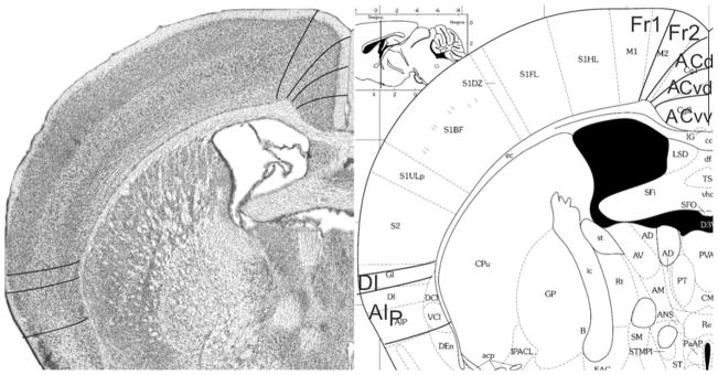
Bregma 2.80 mm (Fig. 1): The lateral boundary of the frontal area 2, Fr2, is approximately equal to the boundary between the prelimbic area (PrL) and the frontal association cortex (FrA). Fr2 is equal to the dorsolateral part of PrL, in contrast to Fig. 2. PrL corresponds to the very high activity of acetylcholinesterase in layer III, rather than to the characteristics visible in the Nissl stain. At this level PrL encompasses, in addition to area Fr2, the dorsal anterior cingulate area (ACd) and the dorsal part of the prelimbic area (PLd); see Appendix 1 for differentiating cytoarchitectonic characteristics. In the ventral part of the medial PFC, which encompasses the ventral prelimbic area (PLv), the infralimbic area (IL) and the medial orbital area (MO), the general density of cell-packing is higher than in the dorsal part of the medial PFC. These three areas offer a more detailed parcellation of the ventral part of the medial PFC than shown in the atlas, in which the whole ventral part of the medial PFC consists of only the medial orbital area (MO). On the lateral side of the frontal lobe in Franklin and Paxinos (2008), the dorsolateral orbital area DLO is specified as a more or less quadrangular field along the ventro-lateral side of the frontal lobe (Figs. 1, 2). In the parcellation of Van de Werd et al. (2010), only the dorsal agranular insular areas AId1 and AId2 are present as areas of the lateral PFC. In the mouse, Van de Werd et al. (2010) did not find the characteristic cytoarchitecture of area DLO as defined in the rat (Van de Werd and Uylings, 2008). The cytoarchitecture of AId1 and AId2 in Fig. 1 is not different from the cytoarchitecture of these areas more posteriorly. At this level, AId1 is located ventrally to the granular cortex, G. The parcellation on the ventral/orbital side of the frontal lobe will be discussed in the evaluation of the next figure, Fig. 2.
Bregma 2.58 mm (Fig. 2): The characteristics of the boundaries in the medial PFC are more clearly visible than they were in Fig. 1. At this level Fr2 is no longer included in PrL, but is now located in FrA, due to the change of the dorsal border of PrL into a more medial position at this level. PrL, therefore, here includes a large part of ACd and PLd. On the lateral side of the frontal lobe, the dysgranular insular area (DI) becomes visible between the ventral end of the band of layer IV granular cells that characterizes the granular cortex and the dorsal agranular insular area, dorsal part, (AId1). In the atlas a DI area is only specified more caudally (see Figs. 5, 6, 7, 8, 9, 10). In Fig. 2 DI is located in FrA. Here the curvilinear arrangement of cells in the dorsal agranular insular areas AId1 and AId2 is better visible than in the previous Figure, as is the difference in the packing density of the cellular columns in these areas. On the ventral/orbital side of the frontal lobe, Van de Werd et al. (2010) distinguish the areas VO, VLO and LO (see Appendix 1), whereas no VLO is defined in the atlas, so that ventral orbital area (VO) encompasses areas VO and a large part of VLO, which are cytoarchitectonically different (see Appendix 1).
Frontal lobe anterior to the forceps minor
Bregma 2.34 mm (Fig. 3): At this level area Fr2 corresponds to the medial part of the secondary motor area (M2) and this correspondence remains visible more caudally. The cingulate area 1, Cg1, is now indicated in the atlas, which is approximately in the same location as ACd. The dorsal boundary of PrL has moved a little more into ventral direction. PrL now encompasses PLd and a dorsal part of PLv.
The location of area VO, which is different from the ventral orbital area (VO), now contacts the retrobulbar region, i.e. the region behind the olfactory bulb encompassing the anterior olfactory nucleus. VO, MO, IL and the ventral part of PLv, are located in MO. At this level, VLO is largely in agreement with VO.
In the lateral PFC, the atlas defines a ventral agranular insular area, AIV, at this level, which roughly corresponds to AId2. In Van Eden and Uylings (1985), Ray and Price (1992), and Van de Werd and Uylings (2008) AIV in the rat is defined as an area in the dorsal bank of the rhinal fissure. In the mouse, however, the AIv characteristics are not clearly found, so that they are not specified in the mouse sections. The dorsal agranular insular area, AID, is somewhat larger than AId1.
Bregma 2.10 mm (Fig. 4): The areas ACd and Cg1 are nearly equal in size and position. PrL is nearly equal to PLd plus PLv of PL, and AId1 and AId2 are approximately equal to the areas AID and AIV, respectively. The cortical layers in VLOp are more homogeneous than in area VLO in the anterior (Figs. 1, 2, 3). VLOp is approximately equal to area VO.
Frontal lobe anterior to the genu of the corpus callosum
Bregma 1.94 mm (Fig. 5): The areas of the medial PFC are well distinguishable by the cytoarchitectonic differences in layer II, the cellular columns in the areas Fr2 and ACd, and the arrangement of cells in the layer VI in rows, parallel to the cortical surface in the areas PLd, PLv, IL and MO (see Appendix 1). PrL is approximately in the same location as PLd and PLv. On the lateral side of the frontal lobe, the prefrontal cortical layers can be followed as far as the piriform cortex. Cytoarchitectonic features of LO are at this level not distinguishable.
Bregma 1.70 mm (Fig. 6): The major change with the previous figure is the absence of area AId2 and the presence of the posterior agranular insular area (AIp). The area AIp is distinguished by the lower cell density in layer III and the small cells of layer V in comparison with AId1 (see Appendix 1). At this level, the atlas maintains the AID and AIV designations. In the medial PFC, the ventral border of PLv is more ventral than the ventral border of PrL. The ventral border of MO is roughly the ventral boundary of IL as it is in Fig. 5.
Bregma 1.42 mm (Fig. 7): Within area M2, boundary Fr2/Fr1 is easily defined by the typical characteristic differences in layer II, the position of layer V in relation to the pial surface, and the difference in the cellular columns in layers V and VI on both sides of the boundary. Area ACd is roughly Cg1. Given the cytoarchitectonic features described in Appendix 1, the PLd/PLv boundary is located within Cg2. The Cg2/IL boundary corresponds with the PLv/IL boundary. At this level in the atlas IL has a greater extension in ventral direction. In the medial PFC we still define the areas PLd, PLv and IL because the features of these areas are more in line with the cytoarchitectonic criteria for these areas than with the criteria for ventral anterior cingulate areas (see Appendix 1). The differences in the lateral prefrontal areas are quite similar to those described in Fig. 6.
Frontal lobe PFC dorsal to the corpus callosum
Bregma 1.18 mm (Fig. 8): Boundary Fr2/Fr1 is defined within M2, as in nearly all previous figures. The characteristics of boundaries Fr2/Fr1 and Fr2/ACd are all present, and typical. The boundary Fr2/ACd is similar to the M2/Cg1 boundary. The characteristics of boundary ACd/ACvd differ from the characteristics of boundary ACd/PLd mainly in as far as in ACvd, layer III is wider and contains less densely packed cells than in PLd. The boundary ACd/ACvd is mainly characterized by the difference in layer II, which is narrow in ACd and shows densely packed cells at the boundary with layer I, but in ACvd this layer is slightly broader and contains densely packed cells (see also Appendix 1 for other features). This boundary is located within Cg1. Boundary ACvd/ACvv is characterized on the basis of layers II, III, V and VI (see Appendix 1). On the basis of their typical characteristics, boundary ACvd/ACvv is in the dorsal half of Cg2. The distinction of AIp instead of AId2 or AIV in this figure is based on the well separated (sub)layers and the smaller cells of layer V in AIp as compared with AId1 or AID.
Bregma 0.74 mm (Fig. 9): Boundary Fr2/Fr1, located in area M2, is mainly defined on the basis of the characteristics of layer V and the cellular columns in layers V and VI. All other boundaries are clearly distinguishable with the characteristics described for the previous figure. At this level, Cg1 is approximately in the same location as ACd. Boundary ACvd/ACvv is in the dorsal half of Cg2. No AId1, as defined in Appendix 1, is detectable at this level.
Bregma −0.46 mm (Fig. 10): In the medial PFC, the figure shows denser packing of cells in the ACv subareas ACvd and ACvv than in the areas Fr2 and ACd. The figure is also illustrative of the absence of cellular columns in ACvd and ACvv and their presence in the dorsal areas Fr2 and ACd. In both ACvd and ACvv the cells of layer VI are arranged in rows, parallel to the cortical surface, but not in Fr2 and ACd. These four clearly distinguishable areas demonstrate that a more detailed parcellation of the medial PFC is possible than is shown in the atlas. Here, ACd is smaller than Cg1. At this level, the atlas indicates the presence of posterior agranular insular area, AIP in the lateral frontal cortex. The distinction and location of DI and AIp are roughly similar to GI, and DI and AIP in the atlas.
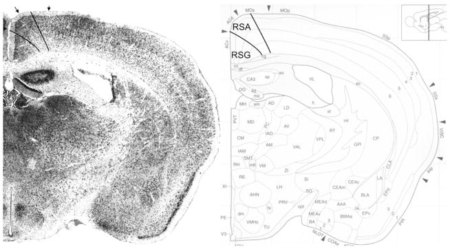
Bregma −0.94 mm: The retrosplenial region which includes the agranular retrosplenial area (RSA) and the granular retrosplenial area (RSG) is immediately caudal to the PFC region. The retrosplenial region is well identifiable by the very typical narrow band of densely packed granular cells in layer II of area RSG. RSA and RSG correspond with RSD and RSGc, respectively. This means that the boundary with M2 is here identical.
Summary
The similarities between the parcellation in the plates of the atlas and our parcellation are found between the areas ACd and Cg1 from Bregma 2.34 mm (Fig. 3) until −0.46 mm (with the exception of Figs. 8, 10), between the combined areas PLd and PLv, and PrL (except for the most anterior sections where PrL is positioned dorsomedially), and in the position of area Fr2 as medial part of area M2. ACd, however, starts more anteriorly in our parcellation than area Cg1. Area PrL is replaced by Cg2 more rostrally (Fig. 7) than the combined areas PLd and PLv by the combined areas ACvd and ACvv (Fig. 8). The area LO is, in general, nearly similar to area LO (Figs. 3, 4), except for the most anterior sections, where the atlas also distinguishes DLO (Figs. 1, 2).
The main differences between the atlas and our parcellation concern the size of the medial orbital area (MO is much larger than MO) (Figs. 1, 2, 3, 4), the presence of DLO in the atlas and the absence of this area in our parcellation. In our parcellation, the infralimbic area IL starts more anteriorly (Fig. 1) than area IL in the atlas (Fig. 5). The cross-sectional size of area IL is much larger than the one of IL (Figs. 5, 6, 7). In the atlas, the presence of MO in anterior sections is replaced by the presence of IL in posterior sections. In our parcellation, MO and IL are both present in many sections. VO is sometimes located in VO (Figs. 1, 2) and sometimes in MO (Figs. 3, 4). VLO is not defined in the atlas.
Area AIp starts anterior to area AIP by first replacing area AId2 (Fig. 6) and then area AId1 also (Fig. 9). No AIv area is detected in the mouse, while an AIV is specified in the atlas (Figs. 3, 4, 5, 6, 7, 8, 9). In the atlas, AIP replaces the combined areas AID and AIV.
In the areas PL and ACv we distinguish a dorsal and ventral part, PLd and PLv, and, ACvd and ACvv, respectively. In the atlas, such a distinction is not made in the areas PrL and Cg2, respectively.
Comparison with the parcellation by Hof et al. (2000)
In their atlas, Hof et al. have indicated the boundaries between cytoarchitectonic areas by means of arrows positioned at the pial surface. In the original ‘image’-files of Nissl sections in Hof et al., curvilinear boundaries have been assessed according to the ‘Van de Werd et al.’ parcellation. Where cytoarchitectonic characteristics were insufficient, e.g. by artifacts, we had to extrapolate from characteristics visible in the contralateral side, or from an anterior or posterior section.
Frontal pole
In Fig. 11, at Bregma 2.50 mm, the characteristics of the PFC boundaries are difficult to distinguish. They could only be reliably identified together with extrapolation from the contralateral hemisphere and from the section shown in Fig. 12. Some features are recognized without extrapolation. For example, on the medial side, the widening of layer II in ventral direction is clearly visible, as is the higher concentration of cells on the boundary between layers I and II in the dorsal half of the medial PFC. In the areas delineated by us as VO, VLO, LO on the ventral side, and as AId1 and AId2 on the lateral side, mutual differences in the cytoarchitecture are visible that support our parcellation. In the PFC, only four areas are recognized in the atlas of which especially the orbital cortex, lateral part (ORBl) shows at least three different cytoarchitectonic structures.
Frontal lobe anterior to the forceps minor
In Fig. 12 (Bregma 2.40 mm) the areas of the PFC are much easier to distinguish than in the previous figure. Thus, the smooth aspect of the border between layer I and layer II in Fr2 and the irregular concentration of cells of layer II at the boundary with layer I in ACd is now visible. At this level, ACd becomes comparable to ACd. The dorsal and ventral parts of PL are distinguishable by the characteristic features in layer II. The area IL is estimated between the wide layer II of PLv and the wide layer II with densely packed and evenly dispersed cells of MO. The ventral boundaries of Fr2, ACd, PLd and IL, and the lateral boundaries of MO and AId2 correspond with boundaries in the atlas. The structure of VO is quite different from the one in the adjacent areas MO and VLO. What is remarkable and not easy to explain is that in the atlas the area ORBl in Fig. 12 is localized in the medial half of the ventral side of the frontal lobe, whereas in Fig. 11 this area occupies the lateral half of the ventral side of the frontal lobe and the ventral part of the lateral cortex. Architectonically, the dorsal agranular insular area, AId, in Fig. 12 is not different from area ORBl in Fig. 11.
In Fig. 13 at Bregma 2.00 mm, area ORBl is localized again in the lateral half of the ventral PFC. The area IL is now better recognizable as a homogeneous area. The difference in the aspect of layer II and the different packing of cellular columns in the areas AId1 and AId2 is decisive for the recognition of these areas. For the assessment of the boundary VLO/LO, the cellular columns in the layers II and III in area VLO and the clustering of cells in layer II of LO are decisive. At this level, the ventral boundaries of Fr2, ACd, and IL, the lateral boundaries of MO and LO, and the dorsal boundary of AId1 correspond with boundaries in the atlas.
Frontal lobe anterior to the genu of the corpus callosum
At Bregma 1.60 mm (Fig. 14), in the medial PFC cells are more densely packed in the ventral areas PLv, IL and MO than in the dorsal areas Fr2, ACd and PLd. The characteristics of the medial PFC areas are all clearly visible. In our parcellation, more areas are recognized than in the atlas. The ventral boundaries of ACd and MO correspond with atlas borders. On the lateral side, the areas DI, AId1 and posterior agranular insular area (AIp) are detected. The area AId1 is distinguished from DI by the cellular columns that are visible in AId1, not in DI. Identification of DI and AId1 is hampered by an artifact in the deeper cortical layers. The dorsal boundary of DI is characterized by the end of the layer IV granular band specified by interrupted lines in Fig. 14. The area AIp is mainly characterized by the cells in layer V which are smaller than in layer V of AId1, and the lower cell density in layer III in AIp (see Appendix 1 for other characteristics).
At Bregma 1.40 mm (Fig. 15), all characteristics of the boundaries, described in Appendix 1, are distinguishable in the medial PFC. Area Fr2 becomes comparable with MOs. PLd and PLv together are approximately in the same position as PL, and IL and MO as IL. In the lateral PFC, boundaries DI/AId1 and AId1/AIp are more or less in accordance with the original boundaries in the atlas between the gustatory cortex and the agranular insular cortex, dorsal part (GU/AId) and between AId and the agranular insular cortex, ventral part (AId/AIv), respectively. The ventral boundary of AIp equals the ventral boundary of AIv.
Bregma 1.30 mm (Fig. 16): In the medial PFC, the medial boundary of Fr2, the ventral boundaries of ACd, PLd and IL coincide with boundaries in the atlas. On the lateral side of the frontal lobe the areas DI, AId1 and AIp approximately correspond with GU, AId and AIv, respectively.
Frontal lobe PFC dorsal to the corpus callosum
Bregma 1.10 mm (Fig. 17): At this level, Fr2 is comparable with the medial half of MOs and ACd corresponds with ACd. The subdivision of ACv into a dorsal (ACvd) and a ventral (ACvv) part is supported by the different cytoarchitecture that is visible in these subareas in this Fig. 17. ACvd and ACvv together coincide with ACv. On the lateral side of the frontal lobe, DI is more or less comparable to AId. At this level, we only distinguish AIp (see Appendix 1 for defining characteristics). AIp is approximately in the same location as AIv.
Bregma 0.70 mm (Fig. 18): At this level, the atlas now also identifies the posterior agranular insular area, AIp in the lateral PFC, which corresponds with AIp. The similarities and differences between the atlas and our distinctions in the medial PFC are as in Fig. 17.
Bregma −1.10 mm (Fig. 19): In contrast with the atlas, in this figure we recognize the retrosplenial region, as the typical granular layer II of the granular retrosplenial area (RSG) is identifiable at this level. The RSG here corresponds with ACv. The dorsal boundary of the agranular retrosplenial area, RSA is defined in area MOs, mainly by the short distance of layer V from the pial surface, due to the absence of layer IV.
Summary
In nearly all sections, area ACd is equal to area ACd (Figs. 12, 13, 15, 16, 17, 18). Area Fr2 is equal to the medial part of area MOs. The combined areas ACvd and ACvv are equal to the area ACv in the atlas (Figs. 17, 18). Differences in size are visible between the areas ORBm and MO (Figs. 11, 12), and between IL and IL (Figs. 13, 14, 15, 16), as ORBm and IL are much larger than MO and IL, respectively. In the atlas ORBm (Figs. 11, 12) is replaced by IL posteriorly (Fig. 14, 15, 16). In our parcellation, the areas MO and IL are nearly always both visible in a section. In the atlas, the ventral orbital area is not recognized as a separate area. The correspondence of ventrolateral area ORBvl varies in the atlas in each figure: in Fig. 11 with VO and parts of VLO and MO; in Fig. 12 with MO; in Fig. 13 with VO and VLO.
Comparison with the parcellation by Rose (1929)
Because of the excellent quality of the figures and the description of the cytoarchitecture, the atlas of Rose is worth discussing. In the atlas of Rose (1929) boundaries are indicated by arrows placed at the surface.
Frontal lobe anterior to forceps minor
In Fig. 20 the medial boundary of Fr2 is approximately comparable with a border indicated by Rose, as is also the ventral boundary of PLv. The agranular Fr2 is located in the part of the cortex that is mentioned as granular cortex by Rose. On the lateral cortex, however, we define the dorsal boundary of the agranular insular area ventral to the boundary between the granular and agranular cortex in the Rose atlas, thus considering the dorsal part of the Rose area ai 1 as belonging to the granular cortex. We based the dorsal boundary AId1 on the cellular columns, the broad, densely packed layer II and the near distance of layer V to the cortical surface. The medial boundary of ai 1 corresponds to the lateral boundary of VLO. Rose defined only one or two ventral PFC areas at this level.
Fig. 20.

Implementation of ‘Van de Werd et al. (2010)’ boundaries in section through frontal lobe anterior to forceps minor of Rose (1929)
At the coronal level of Fig. 21, the extent of the agranular cortex is similar in our parcellation to the extent of the agranular cortex in the Rose parcellation. The medial PFC areas are well definable on the basis of our criteria. Area Fr2 is smaller and positioned between the boundaries of Praecag. This is probably caused by a slightly different appreciation of characteristics, such as our preference for the location of the change in the position of layer V at the lateral boundary of Fr2, and, at the medial boundary of Fr2, our choice for the difference in the packing density of the cellular columns in determining boundary Fr2/ACd. Here, areas ACd, PLd, PLv, IL and MO are rather easy to define according to the criteria specified in Appendix 1.
Fig. 21.

Implementation of ‘Van de Werd et al. (2010)’ boundaries in section through frontal lobe near forceps minor of Rose (1929)
Frontal lobe anterior to genu of the corpus callosum
In Fig. 22, the combined areas ACd and Fr2 are approximately comparable to Praecag. The areas PLd, PLv and IL are also easily definable (Appendix 1). On the lateral side of the frontal lobe, the boundary DI/AId1 is equal to the boundary between the anterior granular insular area (i 1) and the anterior agranular insular area (ai 1). The ventral border of AIp is approximately the ventral border of ai 1.We define AId1 in the dorsal part of ai 1 (Appendix 1). We agree with Rose that the cells of the claustrum are larger than the cells of the cortical layer VI.
Fig. 22.

Implementation of ‘Van de Werd et al. (2010)’ boundaries in section through frontal lobe anterior to genu of the corpus callosum of Rose (1929)
Frontal lobe dorsal to corpus callosum
In Fig. 23, we distinguish, ventrally to area ACd, the areas ACvd and ACvv. The difference in the packing density of cells is more gradual between ACvd and ACvv than between PLd and PLv in the previous sections. The ventral boundary of ACvd is approximately equal to a ventral boundary of Rose. On the lateral side of the frontal lobe, we distinguish the areas DI and AIp (see Appendix 1) as localized in the Rose area ai 2. The cytoarchitecture of DI is different from the cytoarchitecture of AIp, but in the parcellation of Rose they both are located in area ai 2.
Fig. 23.

Implementation of ‘Van de Werd et al. (2010)’ boundaries in section through frontal lobe just caudal to genu of the corpus callosum of Rose (1929)
Summary
In most sections, area Fr2 agrees with a large part of the Rose regio praecentralis agranularis (Figs. 21, 22, 23). Correspondence is found with Rose boundaries for the boundaries Fr1/Fr2 (Figs. 21, 22), Fr2/ACd (Fig. 20), PLd/PLv (Fig. 22), PLv/IL (Fig. 20), ACvd/ACvv (Fig. 23) and DI/AId1 (Fig. 22).
Comparison with other mouse PFC parcellations
Caviness (1975) and Wree et al. (1983) have published studies on the boundaries of mouse cortical areas, including areas of the PFC. In both studies, a limited number of photographs are presented in which we have implemented the boundaries based on our criteria for delineating the PFC areas.
Caviness (1975)
For the denomination of mouse cortical areas Caviness (1975) has applied a numerical terminology derived from Brodmann (1909) and Krieg (1946).
In Fig. 24, in the medial PFC, it is possible to differentiate the PFC areas Fr2 and ACd mainly on the basis of the packing density of the cellular columns of layers V and VI, and on the cells in Fr2 which are larger than in ACd, rather than on the differences in layer II. Most of area Fr2 is in field 8. In field 24, at least three different areas are distinguishable on the basis of the cytoarchitecture. IL is partly in field 24, and partly in field 25. IL is recognizable by the homogeneous layers II, III and V. The boundaries of MO are estimations because the resolution did not allow us to delineate this area with complete reliability. On the lateral side of the frontal lobe, it is difficult to compare our parcellation with the parcellation of Caviness (1975) because in the two fields 10 and 11, we distinguish five different areas which show only a very restricted relation with the fields 10 and 11.
Fig. 24.

Implementation of ‘Van de Werd et al. (2010)’ boundaries in section through forceps minor of Caviness (1975)
In Fig. 25, area Fr2 largely corresponds with field 8. In field 24 areas ACd, ACvd and ACvv can be distinguished on the basis of the criteria described in Appendix 1. In field 14 the areas DI and AId1 are distinguishable. In field 13 the separation between the cortical layers is characteristic of the identification of area AIp.
Fig. 25.

Implementation of ‘Van de Werd et al. (2010)’ boundaries in section through frontal lobe dorsal to corpus callosum and anterior to hippocampus of Caviness (1975)
Summary
Boundary Fr2/ACd is nearly equal to the boundary between the fields 8 and 24 (Figs. 24, 25). Boundary PLv/IL is approximately equal to the boundary between the fields 24 and 25 (Fig. 24). Boundary AId1/AIp is nearly equal to the boundary between the fields 14 and 13 (Fig. 25).
Most of the other boundaries in this paper are not comparable to the boundaries in our parcellation.
Wree et al. (1983)
Wree et al. (1983) compare Nissl-stained sections with the images generated by the GLI. Boundaries are only presented in the GLI images and indicated by arrow heads.
We have delineated boundaries according to our parcellation system in the Nissl micrograph and subsequently copied them in the GLI image.
In Fig. 26, the areas of the medial PFC as well as the areas in the lateral PFC are clearly distinguishable in the Nissl micrographs according to the criteria specified in Appendix 1. The combined areas PLv, IL and MO correspond to cingulate area 4 (C4), the areas ACd and PLd approximately to the cingulate area 1 (C1). Wree et al didn’t specify different areas in the lateral PFC, but in this figure the whole claustrocortex, Cl, corresponds to DI, AId1 and AIp together.
Fig. 26.

Implementation of ‘Van de Werd et al. (2010)’ boundaries in section through forceps minor of Wree et al. (1983)
In Fig. 27, the lateral boundary of Fr2 is approximately the lateral boundary of the medial precentral area Prcm. Prcm roughly encompasses both Fr2 and ACd. Boundary ACd/ACvd (see Appendix 1) is approximately boundary Prcm/C1. Boundary ACvd/ACvv (see Appendix 1) is equal to boundary C1/C2. Dorsally to the corpus callosum the cingulate areas 1 and 2 coincide with ACvd and ACvv, respectively. At this level, the whole claustrocortex, Cl, in the lateral side of the frontal lobe approximately encompasses DI and AIp.
Fig. 27.

Implementation of ‘Van de Werd et al. (2010)’ boundaries in section through frontal lobe dorsal to corpus callosum and anterior to hippocampus of Wree et al. (1983)
Summary
The boundary PLd/PLv is equal to the boundary C1/C4 (Fig. 26). In Fig. 26, boundary Fr2/ACd is approximately equal to boundary Prcm/C1. In Fig. 27, boundary ACd/ ACvd is nearly equal to boundary Prcm/C1 and boundary ACvd/ACvv is equal to boundary C1/C2. In Fig. 26 the combined areas of DI, AId1 and AIp are equal in size to the claustral cortical area (Cl). In Fig. 27, area AIp is approximately equal to the claustral cortical area (Cl).
Comparison summarized in tables
Comparison of the presence of boundaries between subareas
In Table 1, we have indicated to what extent the boundaries of the PFC subareas as described by Van de Werd et al. (2010) are recognized in the publications by other authors regardless of the terminology they have applied. Due to the fact that we were sometimes unable to delineate a particular PFC boundary in one of the available micrographs of a publication or atlas, a comparison was not always possible. We have indicated the areas in the frontal pole anterior to the forceps minor before the symbol ‘/’, and the areas caudal to the tip of the forceps minor after the symbol ‘/’.
Table 1.
Comparison boundaries anterior and posterior to tip of the forceps minor
| Van de Werd et al. (2010) | Franklin and Paxinos (2008) | Hof et al. (2000) | Rose (1929) | Caviness (1975) | Wree et al. (1983) |
|---|---|---|---|---|---|
| Fr1/Fr2 | +−/− | −/~ | −+/~ | /~ | /~ |
| Fr2/ACd | −+/+ | ~+/+ | −~/~ | /+ | /~ |
| ACd/PLd | −+/+ | −+/+ | −/+ | /− | /− |
| PLd/PLv | +−/− | +−/~ | −/~ | /− | /+ |
| PLv/IL | −/+ | −/~ | −/− | /− | /− |
| PLv/MO | −/ | −/ | |||
| IL/MO or IL/DP | −/− | +/+ | −/+ | /+ | /+ |
| MO/DP | ~/~ | /+ | ~/+ | /~ | /+ |
| MO/VO | +−/ | ~/ | −/ | ||
| VO/VLO | −+/ | −/ | −/ | ||
| VLO/LO | −~/ | −/ | ~/ | ||
| ACd/ACvd | /+~ | /+ | /− | /− | /+ |
| ACvd/ACvv | /−+ | /− | /+ | /− | /+ |
| GI/DI | ~/~ | /~ | +/~ | /~ | /~ |
| GI/AId1 or DI/AId1 | +/~ | ~/+ | −/~ | /− | /~ |
| AId1/AId2 | −~/− | −/ | −/ | /− | |
| AId2/LO | −+/− | −+/ | −+/ | /− | |
| DI/AIp | /~ | /~ | /~ | /+ | |
| AId1/AIp | /~ | /+ | /~ | /~ | /+ |
/, separation region anterior and posterior to tip of forceps minor; +, good correspondence of boundary; ~, boundary approximately equal; −, no correspondence; symbols in superscript in front of ‘/’ regard the most rostral section(s); symbols in superscript after ‘/’ regard most caudal section(s); no symbol, boundary not indicated
In the publications of Caviness (1975) and Wree et al. (1983), boundaries are only shown in coronal sections caudal to the tip of the forceps minor.
Table 1 indicates that many boundaries show broad agreement with at least one of the publications reviewed and that a few show considerable agreement in at least two atlases, i.e. Fr2/ACd, ACd/PLd, ACd/ACvd, and AId2/ LO.
Comparison of location and extent of subareas
Tables 2 and 3 show the relationship between Van de Werd et al. (2010) areas and areas in the stereotactic atlases reviewed. The original terminology is maintained in the tables. Table 2 considers the frontal lobe anterior to the tip of the Forceps minor, and Table 3 the frontal lobe caudal to the tip of the Forceps minor.
Table 2.
Comparison of PFC areas anterior to the forceps minor
| Van de Werd et al. (2010) | Franklin and Paxinos (2008) | Hof et al. (2000) |
|---|---|---|
| Medial | ||
| Fr2 | ≪PrL → ⋘FrA → ≪M2 | ⋘FRA → ≪MOs |
| ACd | ≪PrL → ≈ Cg1 | ⋘FRA + ≪PL → ≈ACd |
| PLd + PLv | ≪PrL + ≪MO → ≈PrL | <PL +<ORBm → ≈PL + ≪IL |
| PLd | ≪PrL → <PrL | <PL |
| PLv | ≪MO → <PrL + ≪MO | <ORBm → ≪PL + ≪IL |
| IL | ⋘MO | ≪ORBm → ≪IL |
| MO | ≪MO | ≪ORBm + ⋘ORBvl → ≈ORBvl → ≈ORBm |
| Lateral | ||
| AId1 + AId2 | <DLO + ⋘LO →<AID + <AIV | ⋘ORBl + ⋘FRA → ⋘MOp + ≪AId → ≈AId |
| AId1 | ≪DLO + ⋘LO → <AID | ⋘ORBl + ⋘FRA → ⋘MOp → <AId |
| AId2 | ≪DLO + ⋘LO → <AIV + ≪AID | ⋘ORBl → ≪AId |
| Ventral | ||
| LO | ≪DLO + <LO → ≈LO | <ORBl → <AID → <ORBl |
| VLO | ≪LO + ≪VO → ≈VO | ≪ORBvl + ⋘ORBl → ≪ORBl + ⋘AId → ≪ORBvl + ≪ORBl |
| VO | <VO → ≪VO →⋘MO | <ORBvl → <ORBl → ⋘ORBm + ≪ORBvl |
⋘, ‘Van de Werd et al.’ area is a very small part of; ≪, VdW-area is a small part of; <, VdW-area is a large part of; ≈, VdW-area is equal or approximately equal to; +, together with; →, this changes in caudal direction into
Table 3.
Comparison of PFC areas posterior to tip forceps minor
| Van de Werd et al. (2010) | Franklin and Paxinos (2008) | Hof et al. (2000) |
|---|---|---|
| Medial | ||
| Fr2 | <M2 | <MOs |
| ACd | ≈Cg1 | ≈ACd |
| PLd + PLv | ≈PrL → ≈PrL + ≪IL → ≈Cg2 | ≈PL + ≪IL → ≈PL → ≈PL + ≪IL |
| PLd | <PrL → ⋘Cg1 + ≪Cg2 | ≈PL →<PL |
| PLv | <PrL → ≪PrL + ≪IL → <Cg2 | ≪IL → ≪PL → ≪IL |
| ACvd + ACvv | ≪Cg1 + ≈Cg2 → ≈Cg2 | ≈ACv |
| ACvd | ≪Cg1 + ≪Cg2 → ≪Cg2 | <ACv |
| ACvv | <Cg2 | <ACv |
| IL | <IL → ≪IL | <IL |
| MO | ≪IL | ⋘IL |
| Lateral | ||
| DI | <AID → ≈GI → ≈DI → ≈GI | ≈GU → ≪AId →<GU |
| AId1 + AId2 | ≪AID + ≈AIV +<LO | ≈AId |
| AId1 | ≪AID + <AIV → ≈DI →<AID | ≪AId → <AId + ≪GU → ≈AId |
| AId2 | ≪AIV + <LO | ≪AId |
| AIp | <AIV + ≪LO → ≈AIV + ≪AID → ≪AIV + ≈AID → ≈DI + ≈AIP | ≪AId → ≈AIv + ≪AId → ≈AIp |
⋘, ‘Van de Werd et al.’ area is a very small part of; ≪, VdW-area is a small part of; <, VdW-area is a large part of; ≈, VdW-area is equal or approximately equal to; +, together with; →, this changes in caudal direction into
In Table 2, the delineations of PFC areas differ widely in the frontal pole. It is only just before the forceps minor that correspondence is found for area ACd with the comparable area Cg1 in the Franklin and Paxinos (2008) atlas as well with the comparable area ACd in the Hof et al. (2000) atlas. Further, correspondence is found just rostral to the forceps minor for the Van de Werd et al. (2010) areas PL (i.e. PLd + PLv), LO and VLO with areas Cg2, LO and VO, respectively, in the atlas of Franklin and Paxinos (2008), and with area ORBl in the atlas of Hof et al. (2000). Also the combined areas AId1 and AId2 are comparable with the Hof et al. (2000) area AId just rostral to the tip of the forceps minor. The atlas of Franklin and Paxinos (2008) and the atlas of Hof et al. (2000) show a good mutual correspondence between the secondary motor areas M2 and MOs, and for the medial orbital areas MO in these atlases at Bregma 2.58 and 2.34 mm, and ORBm at Bregma 2.50 and 2.40 mm, respectively.
In Table 3 the relation of the areas Fr2 and ACd in Van de Werd et al. (2010) to areas in the atlases of Franklin and Paxinos (2008) and Hof et al. (2000) is very stable, as is seen in successive figures. Equal location is only found for area ACd and areas Cg1 and ACd, respectively. The combined Van de Werd et al. (2010) areas ACvd and ACvv correspond with area ACv in Hof et al. (2000). The transition of the prelimbic cortex to the ventral part of the anterior cingulate cortex is at Bregma 1.42 in Franklin and Paxinos (2008), after Bregma 1.30 in Hof et al. (2000) and Van de Werd et al. (2010). The Franklin and Paxinos (2008) area AIV at Bregma 1.42 mm is equal to the Hof et al. (2000) area AIv at Bregma 1.42 mm. The anterior boundary of the posterior agranular insular area (AIp) in Van de Werd et al. (2010) is more rostral than the anterior boundary of this area in Franklin and Paxinos (2008) and Hof et al. (2000). This may be explained by a difference in cytoarchitectonic criteria used. Fluctuation in the position of areas in the ventral side of the frontal lobe is visible in Hof et al. (2000). Table 2 shows that in general no stable relation is found in position and size between ventral areas that are specified in the different parcellations studied.
Discussion
The aim of this study has been to review the similarities and differences that are met in the parcellation of the mouse PFC by different investigators. Clarity about the anatomical substrate of the PFC is important to avoid miscommunication in the evaluation of results obtained by tracing, morphometric, lesion and neurophysiological studies.
As extensive series of coronal sections of the PFC are only found in the atlases, we will mainly discuss the difference between the parcellation in the atlases, particularly the Franklin and Paxinos atlas, and the Van de Werd et al. boundaries. The Results show that miscommunication is quite likely, since we have detected that (a) different terms are used for the same cortical structure and (b) cortical areas specified by a comparable term may have different locations/extents.
Some examples of different naming of the same cortical structure are the following ones. The term ‘ventrolateral orbital area’ VLO lacks in the atlas of Franklin and Paxinos, while DLO lacks in Van de Werd et al. The term ‘dorsal agranular insular area, ventral part (AId2) and the term ‘agranular insular cortex, ventral part’ (AIV) are applied for the same part of the cortex on the lateral side of the frontal lobe. The terms ‘area Fr2’, ‘secondary motor cortex (M2 or MOs)’, ‘precentral agranular area (Prcag)’, ‘cortical field 8’ and ‘medial precentral area (Prcm)’ are used to indicate the dorsomedial PFC subarea, which, among other things, is involved in eye movements. It has to be pointed out that Fr2 differs in extent largely from areas M2 and MOs.
Some examples of cortical areas specified by comparable names which have different locations/extents are the following. The difference between extension and location of ACd and Cg1 results in a definition of ‘dorsal anterior cingulate area’ ACd in the medial crown of the frontal pole at a location within the ‘prelimbic area’ PrL specified by Franklin and Paxinos. As a consequence, the extension and location of prelimbic area PL differ from the PrL area. Other examples are the ‘medial orbital area (MO)’ and the ‘infralimbic area (IL)’. The extent of the areas MO and IL is large in the stereotactic atlases, while both MO and IL are quite restricted in the ‘Van de Werd et al.’ parcellation.
The ‘ventrolateral orbital area ORBvl’ in the Hof et al. (2000) atlas and the ‘ventral orbital area VO’ in the Franklin and Paxinos (2008) atlas differ in location and extent from the ‘ventrolateral area’ VLO and ‘ventral orbital area’ VO in the ‘Van de Werd’ parcellation, respectively. Some of the differences in parcellation can be explained by the use of another staining method next to the Nissl staining. So it is clear from the atlas of Franklin and Paxinos (2008) that for the definition of the prelimbic area they probably rely on the data of acetylcholinesterase (AChE)-stained sections. This location of PrL generally agrees with our PL, but differs at the “most frontal” sections (Figs. 1, 2). We have consequently used the same criteria to define PL, also in the most frontal sections. In addition, Van de Werd et al. defined a distinction between a dorsal and a ventral part in the prelimbic area (PL). This is corroborated by studies in the mouse by Rose (1929), Wree et al. (1983) and Van de Werd et al. (2010) and by studies in the rat by Heidbreder and Groenewegen (2003), Groenewegen and Uylings (2010) and Van de Werd and Uylings (2008). The distinction between a dorsal and a ventral part in ACv (Van de Werd et al. 2010) looks a rather new subdivision, but a discrimination between ACvd and ACvv has been made before by Rose (1929) and Wree et al. (1983), see Figs. 23 and 27.
In the mouse, Franklin and Paxinos (2008) distinguish the dorsolateral orbital area (DLO) anterior to the agranular insular areas (AID) and (AIV). This distinction is not made in the other atlases and publications on mouse brain as reviewed in this study. In the rat prefrontal cortex, however, the dorsolateral orbital area (DLO) has been considered as an area that is functionally and cytoarchitectonically different from the agranular insular areas (e.g., Ray and Price 1992; Van de Werd and Uylings 2008; Groenewegen and Uylings 2010; Hoover and Vertes 2011). In the mouse we could not define a DLO.
In the rat, Van Eden and Uylings (1985), Ray and Price (1992), and Van de Werd and Uylings (2008) distinguished the ventral agranular insular area (AIv) on the dorsal bank of the rhinal fissure, but we were unable to distinguish AIv on the dorsal bank of the mouse. In the mouse we defined the dorsal bank of the rhinal fissure largely as LO. Given the observed cytoarchitectonic features, we do not consider the mouse area AId2 to be equivalent with the rat area AIv (Van de Werd and Uylings 2008), but with the rat area AId2. Just before the forceps minor this region has been specified as AIV by Franklin and Paxinos (2008). On the ventral side of the frontal lobe, the distinction of both subareas, VLO and VO is corroborated by cytochemical characteristics in the mouse (Van de Werd et al. 2010) and supported by the tracing studies in the rat (Groenewegen 1988; Ray and Price 1992; Reep et al. 1996; Schilman et al. 2008).
Descriptions of the cytoarchitecture of areas in the region of the PFC were also published by Caviness (1975), De Vries (1912) and Tsuneda (1937). The latter two authors, however, illustrate the cytoarchitecture only in restricted parts in their studies, so that the boundaries could not be evaluated and, therefore, are not discussed any further. The cytoarchitectonic criteria used by Caviness (1975) are more detailed, but only a few figures are presented with fewer subareas than observed in the Van de Werd et al. (2010) parcellation.
The boundaries we implemented on the original photographs were based on the criteria described in Van de Werd et al. (2010) and summarized in Appendix 1. Overall these criteria could well be applied to the photographs. In a photograph, however, boundaries are more difficult to assess than when the sections are examined under the microscope. The limitation of the examination in a photograph and the limited number of photographs presented in some publications may be responsible for less precise boundaries in those photographs where the Van de Werd et al. criteria could not be fully applied. Especially, the most rostral cross-sectional boundaries had to be partly extrapolated from more caudal cross-sections. We only selected Nissl-stained photographs which contained PFC areas, for the assessment of boundaries in the PFC. The Nissl staining is preferred to delineate the PFC boundaries (Van de Werd et al. 2010; Paulussen et al. 2011), because Nissl staining has proved to be superior to any other staining in visualizing boundaries in general (Van de Werd and Uylings 2008; Van de Werd et al. 2010; Uylings et al. 2010). The Nissl staining is also the staining generally applied in morphometric studies, tracing studies and physiological studies for defining the location of an electrode.
In the atlases and publications reviewed, five different mouse strains have been studied. With the assistance of the criteria described in Appendix 1 all PFC areas could be defined in these five strains.
Our cytoarchitectonic descriptions focus upon the characteristics at the boundaries (Van Eden and Uylings 1985; Uylings and Van Eden 1990; Van de Werd and Uylings 2008; Van de Werd et al. 2010; Uylings et al. 2010) in contrast to the generally applied procedure of describing cytoarchitectonic characteristics of whole subareas. In addition, we used the requirement that the boundaries are described in such a way that on the basis of these descriptions the boundaries can be reproducibly positioned by students of PFC. It is worth mentioning that a previous, comparable cytoarchitectonic approach (Van Eden and Uylings 1985; Uylings and Van Eden 1990; Van de Werd and Uylings 2008) has resulted in a parcellation of rat PFC that better ‘fits’ the tracing/connectivity studies with the compartments in the thalamic mediodorsal nucleus, the thalamic midline and intralaminar nuclei, the basal ganglia and amygdala (e.g., Groenewegen 1988; Groenewegen et al. 1990; Schilman et al. 2008; Groenewegen and Uylings 2010; Hoover and Vertes 2011), and functional studies (e.g., Heidbreder and Groenewegen 2003; Dalley et al. 2004). Our parcellation of mouse PFC subareas is in line with the one of rat PFC subareas. Therefore, we expect that our cytoarchitectonic criteria and parcellation of the mouse PFC will be very useful for a more precise localization of electrodes (e.g., Herry and Garcia 2002; Bissonette et al. 2008), microdialysis probes (e.g., Van Dort et al. 2009), receptor binding sites and mRNAs expression (e.g., Amargós-Bosch et al. 2004; Lidow et al. 2003), as well as for anatomical guidance of neuroimaging studies (e.g., Barrett et al. 2003) and tracing neural connections to and from mouse frontal cortical areas (Charbonneau et al. 2012; Parent et al. 2010).
With this review, we address a topic which is essential for the understanding of the functions of different mouse PFC subareas, and ultimately for the iConnectome (e.g., Hintiryan et al. 2012) and the digital database for multidisciplinary information incorporation, interpretation and reference system (Hawrylycz et al. 2011).
Acknowledgments
This study was supported by Grant RO1 MH61578 (G.Rajkowska (P.I.); H.B.M.U.). We thank Dr. L.J.A. Huisman for his linguistic assistance, and Drs. W.J.A.J. Smeets, G. Rajkowska and M.P. Witter and the reviewers of this journal for their constructive critical comments on a previous version of this manuscript.
Abbreviations
- ACd
Dorsal anterior cingulate cortex
- ACv
Ventral agranular cingulate area
- ACvd
Ventral agranular cingulate area, dorsal part
- ACvv
Ventral agranular cingulate area, ventral part
- AId1
Dorsal agranular insular area, dorsal part
- AId2
Dorsal agranular insular area, ventral part
- AIp
Posterior agranular insular area
- cc
Corpus callosum
- DI
Dysgranular insular area
- DLO
Dorsolateral orbital area
- Fr1
Frontal area1
- Fr2
Frontal area2
- G
Granular cortex
- GI
Granular insular area
- IG
Indusium griseum
- IL
Infralimbic area
- LO
Lateral orbital area
- MO
Medial orbital area
- PFC
Prefrontal cortex
- PL
Prelimbic area
- PLd
Prelimbic area, dorsal part
- PLv
Prelimbic area, ventral part
- RSA
Agranular retrosplenial cortex
- RSG
Granular retrosplenial cortex
- VLO
Ventrolateral orbital area
- VLOp
Posterior ventrolateral orbital area
- VO
Ventral orbital area
Appendix 1: Characteristics
Cytoarchitectonic characteristics of boundaries (Van de Werd et al. 2010).
Medial prefrontal subareas anterior to the corpus callosum
Boundary Fr1/Fr2 (frontal areas 1 and 2)
Columns are seen in both Fr1 (frontal area 1) and Fr2 (frontal area 2), but more prominent and more densely packed in Fr2. The columns regard the layers V and VI, but in Fr1 the arrangement of cells in the layer VI might be horizontal instead of columnar.
The size of the cells of the columns is larger in Fr1 than in Fr2.
The layer V rises gradually in Fr1 to reach its most superficial level at the transition from Fr1 to Fr2. This is due to the progressive loss of cells in the layer IV of Fr1 as it approaches the agranular Fr2.
The layer II shows clefts in Fr1, but in Fr2 the layer II cells join into a smooth, less interrupted layer.
Boundary Fr2/ACd (dorsal anterior cingulate area)
Columns are seen in both areas in the layers V and VI, but they are more densely packed in ACd (dorsal anterior cingulate area) than in Fr2.
The size of the cells of the columns is smaller in ACd than in Fr2.
In the layer II of Fr2 the most superficial cells show a smooth surface with layer I, in ACd the cells of the layer II are very much concentrated on its surface, which is irregular.
Boundary ACd/PL (prelimbic area)
Columns are visible in ACd, not in PL. The layer VI in ACd is part of the columnar structure seen in the layers V and VI of that area, but in PL the cells of the layer V are not arranged in a recognizable structure and the cells of its layer VI are arranged in horizontal lines, parallel to the pial surface.
The layer V shows columns in ACd, but not in PL. The cells of the layer V in PL are, however, densely packed. The cells of layer V are larger in PL than in ACd.
The cells of the layer III in ACd are less densely packed than the cells of the layer III in PL. The layer II in ACd is narrow, its cells are concentrated on its surface, in PL the layer II is broader and its cells are spread more equally over the whole layer.
Anterior to the fornix minor of the corpus callosum the deeper layers of the PFC are not visible and the features of layer II and less so of layer III will then be the decisive factors in positioning the boundary.
Boundary PLd/PLv (the dorsal and ventral part of PL)
In the prelimbic area (PL) we distinguish a dorsal part PLd and a ventral part PLv.
The layers V and VI are more densely packed in the ventral than in the dorsal part of PL. The basic structure of these layers remains, however, the same for the ventral as well as the dorsal part of PL.
In both PLd and PLv, the cells of the layer III are less densely packed than in the neighboring layers. As a result the layer III is lighter in appearance in both parts of PL. The layer II is narrower and more densely packed in PLd than in PLv, where the layer is broader and the cells are less densely packed.
Boundary PL/MO (medial orbital area)
In the most frontal part of the PFC PL borders MO, due to absence of the infralimbic area (IL) at that level. The main characteristic of the boundary between PL and medial orbital area (MO) is the equally dispersed cells of the layer II in MO in contrast to the unequal spread of cells in the layer II in PL.
Layer III separates layer II and V more clearly in PL than in MO.
Boundary PL/IL (infralimbic area)
The layers II, III and V are well distinguishable from each other in PL, but in the infralimbic area (IL) they are homogeneous. Some cells of the layer II of IL spread into the layer I, but not in PL or much less so. The cells in layers II–V are smaller in IL than in PL.
The contrast between the clearly distinguishable layer III in PL and the homogeneity of this layer with the neighboring layers in IL is often the easiest sign to determine the boundary between the two areas.
It should be noted that the homogeneity of the layers II, III and V is not always complete in IL as sometimes the layer II might be still distinguishable from the other layers. The layer VI shows a horizontal arrangement of its cells in both PL and IL (infralimbic area).
Boundary IL/MO
The boundary between the infralimbic area (IL) and the medial orbital area (MO) is characterized mainly by the difference in layer II which is homogeneous with the layers III and V and with spreading of cells of the layer II into layer I in IL, while in MO layer II has a sharp border to the layer III.
The cells of the layer II are very equally dispersed in MO, but less so in IL. The cells of layer II are smaller in IL than in MO.
Boundary MO/VO (ventral orbital area)
The boundary between the medial orbital (MO) and ventral orbital (VO) area is determined mainly by layers I–III. Generally the layer II of the medial orbital area (MO) is sharply separated from the layers I and III and the cells in it are rather equally dispersed. In the ventral orbital area (VO), the cells of layer II tend to spread into the layer I and the cells in this layer are less densely packed than in MO. Also some clustering is present in the layer II in VO. The layer III in MO may show fine columns, the layer III in VO usually does not.
Medial subareas caudally to the genu of the corpus callosum
Boundary ACd/ACv (ventral anterior cingulate area)
Columns are seen in ACd but not in ACv (ventral anterior cingulate area).
The cells of the layer VI in ACd are part of the characteristic columnar structure of that area, but the cells of the layer VI in ACv are arranged in horizontal lines.
The cells of the layer V are arranged in columns in ACd, but not in ACv. The cells of the layer V are densely packed in ACv, not in ACd.
In both ACd and ACv, the layer III is easily distinguishable from the neighboring layers by its light appearance.
The layer II of ACd is narrow and its cells are irregularly concentrated on its surface while in ACv the layer II is broader and the cells are spread more equally.
Boundary ACvd/ACvv
In ACv a dorsal part (ACvd) and a ventral part (ACvv) are distinguished.
In all layers, the cells are more densely packed in the ventral than in the dorsal part of ACv. In both ACvd and ACvv, the layer III has a light appearance due to the fact that its cells are less densely packed than in the neighboring layers.
The layer II is narrower and more concentrated in ACvd than in the broader layer II of ACvv.
Difference between PL and ACv
The contrast of the layer III with the neighboring layers is clearer in ACv than in PL. As a consequence the difference between the areas ACd and ACv is less than between the areas ACd and PL. The border between the layers II and I is sharper in ACv than in PL.
Ventral PFC subareas
The ventral areas are known as the ventral orbital (VO), the ventrolateral orbital (VLO) and the lateral orbital (LO) area and they are distinguished by the following characteristics.
Boundaries VO/VLO/LO
In VO, the cells of the layer II are not arranged in a recognizable structure. They are unequally spread with some cells spreading into the layer I seeking contact to the retrobulbar region. Also some clustering is present in the layer II in VO.
In VLO, the cells of the layers II and III are arranged in curvilinear vertical columns. VLO is usually situated at the ventral notch, the indentation seen on the ventral side of the frontal lobe. The main characteristic of the lateral area (LO) is the clustering of cells in its layer II with a sharp transition of that layer to the layer III.
The VLO differs from its posterior part, VLOp, by the following features. In VLO, the layers III, V and VI are separated by open zones of low cell density. In the posterior part of VLO, distinguished as VLOp, however, all layers are more homogeneous.
Lateral PFC subareas
Boundary of the granular (G) or dysgranular insular cortex (DI) with the dorsal agranular insular area 1 (AId1)
In the frontal part of the PFC, the dorsal agranular insular area 1 (AId1) borders the granular cortex (G), but in the caudal part of the PFC AId1 borders the dysgranular cortex (DI).
Columns are seen very clearly in the layers V and VI in AId1, not at all or much less impressive and less closely packed in G or DI.
The cells of layer V are smaller in AId1 than in G or DI.
The layers II, III and IV are homogeneous in DI, but in AId1 the layer IV is absent and the layers II and III are well distinguishable from each other.
The cells of the layer III are less densely packed in AId1 than in G or DI.
Boundary AId1/AId2 (dorsal agranular insular area 2)
Columns are seen in both areas, but they are more densely packed in AId2 than in AId1.
The cells of the layer V are smaller in AId2 than in AId1.
The cells of the layer III are less densely packed in AId2 than in AId1.
The layer II is broad in both areas. In AId1 layer II cells are densely packed, but in AId2 the layer II is broken by clefts, its cells partake in the columnar structure of the area and some cells spread into the layer I.
Boundary AId1/AIp (posterior agranular insular area)
In the posterior agranular insular area (AIp), the cortical layers and the claustrum are well separated from each other. If the cell-sparse zones between the layers are included as sublayers, 8 or more (sub)layers can be distinguished. In AId1, the layers are contingent and a columnar arrangement of the cells of the layers V and VI is visible. The cells of layer V of AIp are smaller than the cells of layer V in AId1.
Boundary AId2/LO
Columns are seen in the layers VI, V and II in AId2, but not in LO. Layer I is narrow in LO, broad in AId2. The layer II in AId2 is broad and cells spread to layer I. In LO the layer II shows marked clustering of cells.
Appendix 2
Abbreviations in the Franklin and Paxinos atlas (2008)
- AI
Agranular insular cortex
- AID
Agranular insular cortex, dorsal part
- AIP
Agranular insular cortex, posterior part
- AIV
Agranular insular cortex, ventral part
- Cg1
Cingulate cortex, area 1
- Cg2
Cingulate cortex, area 2
- Cl
Claustrum
- DI
Dysgranular insular cortex
- DLO
Dorsolateral orbital cortyex
- DP
Dorsal peduncular cortex
- fmi
Forceps minor of the corpus callosum
- Fr3
Frontal cortex, area3
- FrA
Frontal association cortex
- GI
Granular insular cortex
- IL
Infralimbic cortex
- LO
Lateral orbital cortex
- M2
Secondary motor cortex
- MO
Medial orbital cortex
- PrL
Prelimbic cortex
- RSD
Retrosplenial dysgranular cortex
- RSG
Retrosplenial granular cortex
- VO
Ventral orbital cortex
Abbreviations in the Hof et al. atlas
- ACd
Anterior cingulate cortex, dorsal part
- ACv
Anterior cingulate cortex, ventral part
- AId
Agranular insular cortex, dorsal part
- AIp
Agranular insular cortex, posterior part
- AIv
Agranular insular cortex, ventral part
- CLA
Claustrum
- DP
Dorsal peduncular area
- fa
Corpus callosum, anterior forceps
- FRA
Frontal association area
- FRP
Frontal pole
- GU
Gustatory cortex
- IG
Indusium griseum
- IL
Infralimbic area
- MOs
Secondary motor cortex
- ORBl
Orbital cortex, lateral part
- ORBm
Orbital cortex, medial part
- ORBvl
Orbital cortex, ventrolateral part
- PL
Prelimbic area
- rf
Rhinal fissure
- TTd
Tenia tecta, dorsal part
Abbreviations in the Rose atlas
- ai 1
Area insularis agranularis anterior
- ai 2
Area insularis agranularis posterior
- i 1
Area insularis granularis anterior
- i 2
Area insularis granularis posterior
- IRa α
Area infraradiata ventralis anterior
- IRb α
Area infraradiata intermedia anterior
- IRc α
Area infraradiata dorsalis anterior
- IRa β
Area infraradiata ventralis posterior
- IRb β
Area infraradiata intermedia posterior
- IRc β
Area infraradiata dorsalis posterior
- Praecag
Regio praecentralis agranularis
- Praecgr
Regio praecentralis granularis
Abbreviations in the Wree et al. study
- C1; 2; 3; 4
Area cingularis 1; 2; 3; 4
- Cl
Claustrocortex
- Prcm
Area praecentralis medialis
Footnotes
Conflict of interest: The authors declare that they have no conflict of interest.
Contributor Information
Henri J. J. M. Van De Werd, Email: werdh@hotmail.nl.
Harry B. M. Uylings, Email: hbm.uylings@vumc.nl.
References
- Amargós-Bosch M, Bortolozzi A, Puig MV, Serrats J, Adell A, Celada P, Toth M, Mengod G, Artigas F. Co-expression and in vivo interaction of serotonin1A and serotonin2A receptors in pyramidal neurons of prefrontal cortex. Cereb Cortex. 2004;14:281–299. doi: 10.1093/cercor/bhg128. [DOI] [PubMed] [Google Scholar]
- Barrett D, Shumake J, Jones D, Gonzales-Lima F. Metabolic mapping of mouse brain activity after extinction of a conditioned emotional response. J Neurosci. 2003;23:5740–5749. doi: 10.1523/JNEUROSCI.23-13-05740.2003. [DOI] [PMC free article] [PubMed] [Google Scholar]
- Bissonette GB, Martins GJ, Franz ThM, Harper ES, Schoenbaum G, Powell EM. Double dissociation of the effects of medial and orbital prefrontal cortical lesions on attentional and affective shifts in mice. J Neurosci. 2008;28:11124–11130. doi: 10.1523/JNEUROSCI.2820-08.2008. [DOI] [PMC free article] [PubMed] [Google Scholar]
- Brodmann K. Vergleichende Lokalisationslehre der Gross-hirnrinde. Barth Verlag; Leipzig: 1909. p. 324. [Google Scholar]
- Caviness VS., Jr Architectonic map of neocortex of the normal mouse. J Comp Neurol. 1975;164:247–263. doi: 10.1002/cne.901640207. [DOI] [PubMed] [Google Scholar]
- Charbonneau V, Laramée ME, Boucher V, Bronchti G, Boire D. Cortical and subcortical projections to primary visual cortex in anophthalmic, enucleated and sighted mice. Eur J Neurosci. 2012;36:2949–2963. doi: 10.1111/j.1460-9568.2012.08215.x. [DOI] [PubMed] [Google Scholar]
- Dalley JW, Cardinal RN, Robbins TW. Prefrontal executive and cognitive functions in rodents: neural and neurochemical substrates. Neurosci Biobehav Rev. 2004;28:771–784. doi: 10.1016/j.neubiorev.2004.09.006. [DOI] [PubMed] [Google Scholar]
- De Vries I. Über die Zytoarchitektonik der groszhirnrinde der Maus und über die Beziehung der einzelnen Zellschichten zum Corpus callosum auf Grund von experimentellen Läsionen. Folia Neuro-Biol. 1912;6:289–322. [Google Scholar]
- Franklin K, Paxinos G. The mouse brain in stereotaxic coordinates. 3. Academic Press, Elsevier; San Diego: 2008. [Google Scholar]
- Groenewegen HJ. Organization of the afferent connections of the mediodorsal thalamic nucleus in the rat, related to the mediodorsal–prefrontal topography. Neuroscience. 1988;24:379–431. doi: 10.1016/0306-4522(88)90339-9. [DOI] [PubMed] [Google Scholar]
- Groenewegen HJ, Berendse HW, Wolters JG, Lohman AHM. The anatomical relationship of the prefrontal cortex with the striatopallidal system, the thalamus and the amygdala: evidence for a parallel organization. Progress in brain research. In: Uylings HBM, Van Eden CG, De Bruin JPC, Corner MA, Feenstra MGP, editors. The prefrontal cortex; its structure, function and pathology. Vol. 85. Elsevier Science Publishers; Amsterdam: 1990. pp. 95–118. [DOI] [PubMed] [Google Scholar]
- Groenewegen HJ, Uylings HBM. Organization of prefrontal–striatal connections. In: Steiner H, Tseng KY, editors. Handbook basal ganglia structure and function: a decade of progress. Academic press; San Diego: 2010. pp. 353–365. [Google Scholar]
- Hawrylycz M, Baldock RA, Burger A, Hashikawa T, Johnson GA, Martone M, Ng L, Lau L, Larsen SD, Nissanov J, Puelles L, Ruffins S, Verbeek F, Zaslavsky I, Boline J. Digital atlasing and standardization in the mouse brain. PLoS Comput Biol. 2011;7(2):e1001065. doi: 10.1371/journal.pcbi.1001065. [DOI] [PMC free article] [PubMed] [Google Scholar]
- Heidbreder CA, Groenewegen HJ. The medial prefrontal cortex in the rat: evidence for a dorso-ventral distinction based upon functional and anatomical characteristics. Neurosci Biobehav Rev. 2003;27:555–579. doi: 10.1016/j.neubiorev.2003.09.003. [DOI] [PubMed] [Google Scholar]
- Herry C, Garcia R. Prefrontal cortex long-term potentiation, but not long-term depression, is associated with the maintenance of extinction of learned fear in mice. J Neurosci. 2002;22:577–583. doi: 10.1523/JNEUROSCI.22-02-00577.2002. [DOI] [PMC free article] [PubMed] [Google Scholar]
- Hintiryan H, Gou L, Zingg B, Yamashita S, Lyden HM, Song MY, Grewal AK, Zhang X, Toga AW, Dong H-W. Comprehensive connectivity of the mouse main olfactory bulb: analysis and online digital atlas. Front Neuroanat. 2012 doi: 10.3389/fnana.2012.00030. doi:10.3389/fnana.2012.00030. [DOI] [PMC free article] [PubMed] [Google Scholar]
- Hoover WB, Vertes RP. Projections of the medial orbital and ventral orbital cortex in the rat. J Comp Neurol. 2011;519:3766–3801. doi: 10.1002/cne.22733. [DOI] [PubMed] [Google Scholar]
- Hof PR, Young WG, Bloom FE, Belichenko PV, Celio MR. Comparitive cytoarchitectonic atlas of the C57BL/6 and 129/Sv mouse brains. Elsevier; Amsterdam: 2000. [Google Scholar]
- Krieg WJS. Connections of the cerebral cortex. I. The albino rat. A. Topography of the cortical areas. J Comp Neurol. 1946;84:221–275. doi: 10.1002/cne.900840205. [DOI] [PubMed] [Google Scholar]
- Lidow MS, Koh PO, Arnsten AFT. D1 dopamine receptors in the mouse prefrontal cortex: immunocytochemical and cognitive neuropharmacological analyses. Synapse. 2003;47:101–108. doi: 10.1002/syn.10143. [DOI] [PubMed] [Google Scholar]
- Parent MA, Wang L, Su J, Netoff T, Yuan L-L. Identification of the hippocampal input to medial prefrontal cortex in vitro. Cereb Cortex. 2010;20:393–403. doi: 10.1093/cercor/bhp108. [DOI] [PMC free article] [PubMed] [Google Scholar]
- Paulussen M, Jacobs S, Van Der Gucht E, Hof PR, Arckens L. Cytoarchitecture of the mouse neocortex revealed by the low-molecular-weight neurofilament protein subunit. Brain Struct Funct. 2011;216:183–199. doi: 10.1007/s00429-011-0311-3. [DOI] [PubMed] [Google Scholar]
- Ray JP, Price JL. The organization of the thalamocortical connections of the mediodorsal thalamic nucleus in the rat, related to the ventral forebrain-prefrontal cortex topography. J Comp Neurol. 1992;323:167–197. doi: 10.1002/cne.903230204. [DOI] [PubMed] [Google Scholar]
- Reep RL, Corwin JV, King V. Neuronal connections of orbital cortex in rats: topography of cortical and thalamic afferents. Exp Brain Res. 1996;111:215–232. doi: 10.1007/BF00227299. [DOI] [PubMed] [Google Scholar]
- Rose M. Cytoarchitektonischer Atlas der Groszhirne der Maus. J Psychol Neurol. 1929;40:1–51. [Google Scholar]
- Schilman EA, Uylings HBM, Galis-de Graaf Y, Joel D, Groenewegen HJ. The orbital cortex in rats topographically projects to central parts of the caudate-putamen complex. Neurosci Lett. 2008;432:40–45. doi: 10.1016/j.neulet.2007.12.024. [DOI] [PubMed] [Google Scholar]
- Tsuneda N. Zur Cytoarchitektonik des Neocortex des Mäusegehirns. Okajimas Folia Anat Jpn. 1937;15:1–47. [Google Scholar]
- Uylings HBM, Van Eden CG. Qualitative and quantitative comparison of the prefrontal cortex in rat and primates, including humans. In: Uylings HBM, Van Eden CG, De Bruin JPC, Corner MA, Feenstra MGP, editors. Progress in brain research. The prefrontal cortex; its structure, function and pathology. Vol. 85. Elsevier Science Publ; Amsterdam: 1990. pp. 31–62. [DOI] [PubMed] [Google Scholar]
- Uylings HBM, Sanz–Arigita EJ, De Vos K, Pool CW, Evers P, Rajkowska G. 3-D Cytoarchitectonic parcellation of human orbitofrontal cortex, Correlation with postmortem MRI. Psychiat Res Neuroimag. 2010;183:1–20. doi: 10.1016/j.pscychresns.2010.04.012. [DOI] [PMC free article] [PubMed] [Google Scholar]
- Van De Werd HJJM, Uylings HBM. The rat orbital and agranular insular prefrontal cortical areas: a cytoarchitectonic and chemoarchitectonic study. Brain Struct Funct. 2008;212:387–401. doi: 10.1007/s00429-007-0164-y. [DOI] [PubMed] [Google Scholar]
- Van De Werd HJJM, Rajkowska G, Evers P, Uylings HBM. Cytoarchitectonic and chemoarchitectonic characterization of the prefrontal cortical areas in the mouse. Brain Struct Funct. 2010;214:339–353. doi: 10.1007/s00429-010-0247-z. [DOI] [PMC free article] [PubMed] [Google Scholar]
- Van Dort CJ, Baghdoyan HA, Lydic R. Adenosine A(1) and A(2A) receptors in mouse prefrontal cortex modulate acetylcholine release and behavioral arousal. J Neurosci. 2009;29:871–881. doi: 10.1523/JNEUROSCI.4111-08.2009. [DOI] [PMC free article] [PubMed] [Google Scholar]
- Van Eden CG, Uylings HBM. Cytoarchitectonic development of the prefrontal cortex in the rat. J Comp Neurol. 1985;241:253–267. doi: 10.1002/cne.902410302. [DOI] [PubMed] [Google Scholar]
- Wree A, Zilles K, Schleicher A. A quantitative approach to cytoarchitectonics. VIII. The areal pattern of the cortex of the albino mouse. Anat Embryol. 1983;166:333–353. doi: 10.1007/BF00305922. [DOI] [PubMed] [Google Scholar]