

Abstract
Background
Late Gadolinium Enhancement (LGE) MRI of ventricular scar has been shown to be accurate for detection and characterization of arrhythmia substrates. However, the majority of patients referred for ventricular tachycardia (VT) ablation have an implantable cardioverter defibrillator (ICD), which obscures image integrity and the clinical utility of MRI.
Objective
To develop and validate a wideband LGE MRI technique for device artifact removal.
Methods
A novel wideband LGE MRI technique was developed to allow for improved scar evaluation on patients with ICDs. The wideband technique and the standard LGE MRI were tested on 18 patients with ICDs. VT ablation was performed in 13 of 18 patients with either endocardial and/or epicardial approach and the correlation between the scar identified on MRI and electroanatomical mapping was analyzed.
Results
Hyper-intensity artifact was present in 16/18 of patients using standard MRI, which was eliminated using the wideband LGE and allowed for MRI interpretation in 15/16 patients. All patients had ICD lead characteristics confirmed as unchanged post- MRI and had no adverse events. LGE scar was seen in 11/18 patients. Among the 15 patients where wideband LGE allowed visualization of myocardium, 10 had LGE scar and 5 had normal myocardium in the regions with image artifacts when using the standard LGE. The left ventricular scar size measurements using wideband MRI and EAM were correlated with R2=0.83, P=0.00003.
Conclusions
The wideband LGE-MRI improves the ability to visualize myocardium for clinical interpretation, which correlated well with EAM findings during VT ablation.
Keywords: ventricular tachycardia, delayed enhancement, MRI, ICD, image artifact, myocardial scar, electroanatomical mapping, LGE, catheter ablation, Arrhythmias, clinical electrophysiology, Ablation/ICD/surgery
Introduction
Late Gadolinium Enhancement (LGE) cardiac MRI is the clinical gold standard for assessment of myocardial scar 1. The characterization of myocardial scar provided by LGE MRI allows accurate identification of arrhythmogenic substrate and ablation sites, and may facilitate periprocedural planning and mapping during VT ablation 2. However, the majority of patients (up to 75%) referred for VT ablation are currently not referred to MRI due to concerns about safety and imaging artifact 3. Potential risks of MRI for patients with ICDs or pacemakers include heating of the tissue adjacent to lead electrodes, mechanical forces, induction of arrhythmias, and alteration of device function 4.
Recent studies have consistently demonstrated the feasibility and safety of LGE-MRI in patients with implantable cardioverter defibrillators (ICD) and pacemakers; however, the imaging artifacts caused by the device generator is highly prevalent and often severely limits interpretation of LGE in the majority of VT patients 5.
Device generator artifact is caused by the multi-kHz frequency shift of tissues 5-10cm away from the device generator. The resulting images have a bright artifact, which is problematic since LGE also renders scar tissue bright 6. Recently, a wideband LGE MRI technique has been reported that can remove these image artifacts and allows more comprehensive evaluation of myocardial scar 7. The aims of this study are 1) to assess the ability of wideband LGE to remove ICD artifacts compared to standard LGE in patients referred for scar-mediated VT and 2) to correlate the scar identified on wideband LGE-MRI with invasive electroanatomic mapping.
Methods
Eighteen patients who had received ICD therapy for VT were referred for cardiac MRI in perioperative planning for potential VT ablation. Both the standard LGE-MRI and the wideband LGE-MRI were performed. Of the 18 patients with VT who had LGE-MRI, 13 underwent VT ablation with high-density electroanatomical maps (EAM) and the findings were compared. Written informed consent was obtained from all participants, and the HIPAA-compliant protocol was approved by the Institutional Review Board.
Wideband LGE MRI Sequence
In standard LGE-MRI, there is a non-selective adiabatic inversion pulse with a spectral bandwidth of approximately 1 kHz. This inversion pulse creates a strong T1-weighed image with excellent contrast between scar and viable myocardium. However, in the presence of an ICD, regions of the heart that are as far as 5-10 cm from the device generator undergo a strong frequency shift of 2-4 kHz, which is well outside of the 1-kHz spectral bandwidth of the inversion pulse used in the standard LGE 7. As a consequence, the affected regions are not properly inverted (or nulled) and are hence hyper-intense, undermining diagnostic interpretation. In the wideband LGE-MRI sequence, the 1-kHz inversion pulse is replaced with a wideband hyperbolic secant inversion pulse of 3.8-kHz bandwidth. This ensures that the myocardium is property inverted by the pulse and hence the hyper-intensity artifact is eliminated 7. In our implementation, the wideband inversion pulse has the same time duration as the standard inversion pulse and as such, the imaging time is the same as the standard LGE. The wideband inversion pulse requires a higher specific absorption rate (SAR) (0.07 W/kg for wideband vs. 0.05 W/kg for standard LGE). However, the overall SAR of both sequences are well below the FDA regulation of 2 W/kg. The wideband inversion pulse requires higher minimum B1 value of 12 uT to satisfy the adiabatic condition, which should be feasible on most commercial MRI systems.
MRI Acquisition
LGE-MRI studies were acquired using a 1.5 Tesla MRI system (Avanto, Siemens Healthcare, Erlangen, Germany). Safety procedures in the literature for MRI of patients with implantable devices are adopted at our institution8. Patients that were pacemaker dependent, or had implantation within 6 months, or abandoned leads were excluded. A physician or nurse practitioner with specialized training in implantable cardiac devices, as well as a representative from the device company, interrogated ICD parameters prior to MRI. All therapies and detections were disabled, and the lead thresholds, impedance, and battery voltage were checked. Continuous hemodynamic and ECG monitoring was performed during the MRI. Immediately after the completion of the MRI protocol, any clinical events were recorded and the device was interrogated again to check for any changes in ICD parameters. All tachycardia detection and therapies were enabled at the conclusion of the study.
For each patient, Gd-DTPA was used at 0.2 mmol/kg body weight. Both standard LGE MRI and the wideband LGE were acquired. For each 2D imaging slice, the standard LGE was immediately followed by the wideband LGE at the same slice. Typically 8-12 short-axis slices (1.6 mm inter-slice gap) and 3-5 long-axis images were acquired to obtain sufficient anatomical coverage of the LV. All the image slice orientations were prescribed based on scout images and a three-point slice definition tool on the scanner. The inversion time (TI) was continuously increased by 10ms every 2 minutes to maintain good suppression of normal myocardium as the gadolinium contrast agent is washed out. The LGE-MRI pulse sequence parameters were: TR/TE=4.1/1.5 ms, FOV=360 mm, FA=25°, readout bandwidth=500 Hz/pixel, slice-thickness=8mm, resolution=1.4mm× 1.9mm, TI=250-400ms. The duration of the complete MRI protocol was approximately 60-80 minutes. The duration of the wideband LGE that was added to the standard cardiac MRI protocol was approximately 10-15 minutes.
Electrophysiological Study and Catheter Ablation
Of the 18 patients with ICD who underwent MRI, 13 were referred for ablation. Electroanatomical mapping was performed using high-density maps using CARTO (Biosense Webster, Diamond Bar, CA) or NavX (St. Jude Medical, Minneapolis, MN) with greater density sampling of regions with low voltage (0.5-1.5mV). Dense scar was defined as <0.5mV and border zone was defined as 0.5-1.5mV. Only dense scar (<0.5mV) was used to measure epicardial scar area.
Epicardial access was left to the discretion of the operator and performed using standard techniques described by Sosa et al. 9. Epicardial access and mapping, when performed, was done prior to endocardial access to minimize exposure to systemic heparin. Endocardial access was obtained with either single or double transseptal with standard BRK-1 guided by Intracardiac Echocardiography, and either Mullens 8F sheath or Agilis deflectable sheaths (St. Jude Medical). Both endocardial and epicardial mapping was performed with either Thermocool 3.5mm (Biosense Webster, Diamond Bar, CA), or Chilli 2 (Boston Scientific, Natick, MA). High density mapping was performed with a duodecapolar multipolar catheter (Livewire 2-2-2mm duodecapolar catheter, St. Jude Medical) as previously described 10. Bipolar signals were filtered at 5-500 Hz and displayed at 100 mm/s.
Artifact and Scar Size Measurements
The area of LV myocardial tissue that had hyper-intensity image artifacts due to ICD when using the standard LGE MRI was measured for each short-axis slice. The measurements were subsequently summed over all the short-axis slices for each patient and were multiplied by the slice thickness (and any inter-slice gap), which yields the total size of artifact in the myocardium. For each patient who had a chest X-ray either before or after MRI, the distance between the ICD and LV was measured based on the anterior-posterior X-ray image. The artifact size measurements and the ICD-to-LV distance were subsequently correlated using a linear regression. Patients with no chest X-ray (patients 6, 8, and 12), the patient with right sided ICD (patient 5) and the patient with ICD overlying LV (patient 17) were excluded from the correlation.
The size of both endo and epicardial scar was measured based on the wideband LGE-MRI. For each patient, the short-axis wideband LGE images with scars were identified. On each of the identified image, a curve was drawn along the endocardial surface of any endocardial scar and along the epicardial surface for any epicardial scar (or both for transmural scar). The total length of the endocardial and epicardial curves was multiplied by the sum of the slice thickness and any inter-slice gap, which gives the endo- and epicardial surface area for the slice. These measurements were added among all the short-axis slices with scars, which yields the total endo- and epicardial scar surface area for the each patient.
On EAM, retrospective electrogram analysis of low voltage regions was performed by two physicians. Scar was measured (cm2) using the incorporated software of the mapping system. Low voltage regions were excluded if there was poor catheter contact or suspected epicardial fat based on the appearance of the local electrograms 11.
Results
The mean age was 52 +/- 13.4 years old, and 94% were male. Mean ejection fraction was 36.7% (+/-15.6), 16% had ischemic cardiomyopathy and 66% had non-ischemic etiologies. Patient clinical characteristics are outlined in Table 1.
Table 1.
Clinical summary of the 18 VT patients with ICDs who underwent cardiac MRI for assessment of myocardial scar.
| Patient Index | Clinical | Wideband LGE Scar Location | CXR Distance (Can to LV Border) (mm) |
|---|---|---|---|
| 1. | Chagas Disease, EF 48% | Basal lateral and apex | 15.2 |
| 2. | Ischemic, EF 33%. | Inferior | 25.9 |
| 3. | Non-ischemic EF 35% | Basal lateral | 18.9 |
| 4. | Non-ischemic EF 40% | Anterior | 48.8 |
| 5. | Ischemic EF 36%, mechanical aortic and mitral valves. | Inferior | Right sided ICD |
| 6. | ARVD, EF 60% | Possible RV free wall. | -- |
| 7. | Brugada, EF 60% | No Scar | 33.2 |
| 8. | Apical Hypertrophic Cardiomyopathy EF 60% | Apical Aneurysm | -- |
| 9. | Ischemic EF 55% | Inferior lateral Endocardial. | 10.2 |
| 10. | Hypertrophic Cardiomyopathy EF 24% | Transmural Apical and entire LV Mid cavity to apex | 44.4 |
| 11. | PVC/Tachycardia related cardiomyopathy EF 30% | No scar | 71.6 |
| 12. | Non-ischemic CM EF 45% | Apex | -- |
| 13. | Non-ischemic EF 23% | No scar | 43.4 |
| 14. | Non-ischemic EF 15% | No scar | 44.1 |
| 15. | Non-ischemic EF 15% | Septum, basal to mid cavity. | 43.8 |
| 16. | Non-ischemic EF 33%, sarcoidosis. | No scar | 25.7 |
| 17. | Non-ischemic EF 10% with Mitral Clip. | No scar, anterior wall not seen due to MRI signal void. | Overlying left ventricle by 31mm. |
| 18. | Non-ischemic EF 36.2% | Small linear scar inferior septum | 56.7 |
ICD artifact was present in 89% (16/18) of patients, obscuring interpretation of multiple LV myocardial segments. Of the two patients without artifact at baseline, one had a right side ICD (patient 5) and the other had lateral position of ICD (patient 11). This patient had longest distance measured among the left sided devices within our patient cohort between the ICD can and the LV border on chest X-ray (71.6mm). The most common artifact location was on the anterior wall of the left ventricle (LV), and nearby areas such as the LV septum and apex. Using the wideband technique, artifact was successfully removed allowing for interpretation of the previously obscured myocardium in 93% (15/16). Figure 1 shows a comparison between standard LGE, wideband LGE and EAM map. Apical and basal lateral scars, which are obscured using the standard LGE, are clearly shown in the wideband LGE, which correlates well with the EAM scars in the same segments. The only case (patient 17) where interpretation of myocardial segments could not be done had the ICD can in close proximity to the LV border, overlying it by 31mm on chest X-ray. In this patient, as shown in the example of Figure 2b, the ICD is sufficiently close to the myocardium to cause an MRI signal void, which was not overcome using the wideband LGE. Figure 2c shows the negative correlation between hyper-intensity artifact size and the ICD-to-LV distance with R2=0.53.
Figure 1.
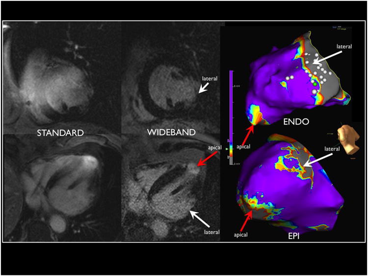
Standard pulse sequence MRI with significant hyper-intensity artifact from the Implantable Cardioverter Defibrillator (Left) compared to wideband Late Gadolinium Enhancement MRI (right) in a patient with Chagas disease and apical and basal lateral scar. Combined epicardial-endocardial mapping identified scar that correlated with imaging.
Figure 2.
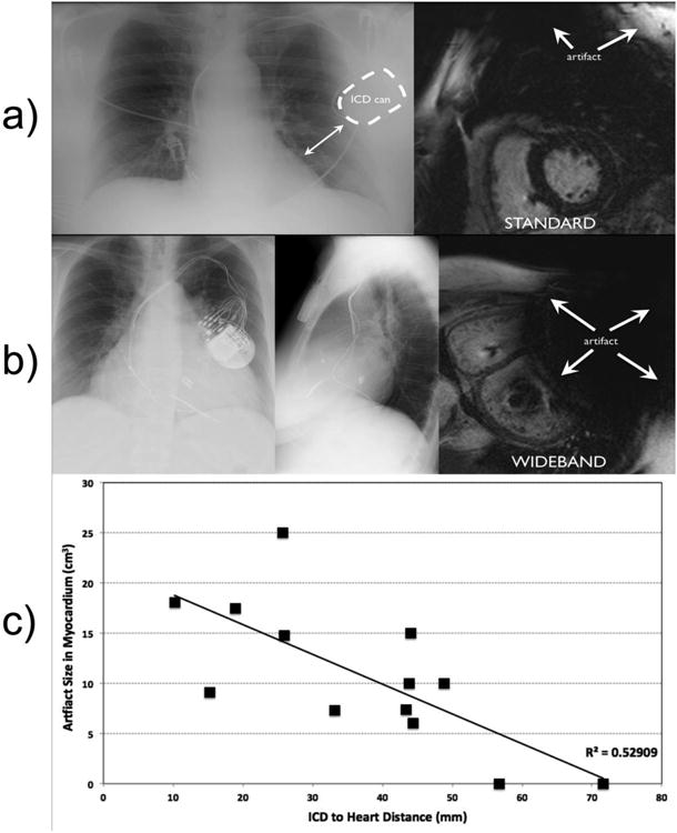
Relationship between can distance from heart on chest x-ray and MRI artifact using standard LGE. a): patient with longest distance between ICD and left heart border with no artifact (upper right) on standard MRI. b): Chest X-ray of patient with closest ICD to the left heart border showing extensive signal void artifact that cannot be corrected by the wideband LGE due to intra-voxel MRI signal dephasing. c): The ICD-to-LV distance and the artifact size is negatively correlated.
All patients had lead thresholds, impedance and sensing checked before and after MRI and no significant changes were observed. No adverse clinical events were observed during the MRI scanning. Overall 61% (11/18) patients had LGE scar seen on MRI. Among the 15 patients where wideband allowed improved visualization of myocardium, 10 (66%) had scar in the artifact region when using standard LGE. The other 5 (33%) had normal myocardium in the artifact region, an example of which is shown in Figure 3.
Figure 3.
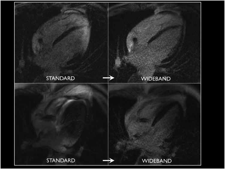
Elimination of can artifact with wideband technique in two patients reveals normal myocardium in regions previously obscured from clinical interpretation.
Figure 4 outlines the breakdown of the patients, and MRI and EAM findings. Among the 18 patients referred for MRI, 13 underwent mapping and ablation of VT. Of the 13 patients, 9 had scar seen on wideband LGE, and the other 4 patients underwent VT ablation at the discretion of the physician and patient even in the absence of LGE scar. Of the 9 patients, one patient (patient 12) underwent activation mapping of a premature ventricular contraction (PVC) with incomplete substrate voltage mapping. Electroanatomical maps were created using the CARTO (n=9) and NavX (n=4) systems. The average map density was 653 +/-685 points. Only dense scar (<0.5mV bipolar) was used to measure epicardial scar size.
Figure 4.

Flow chart showing breakdown of patients who underwent MRI referred for Ventricular Tachycardia ablation and patients had scar present on MRI and/or on Electroanatomical Map (EAM).
EAM scar was detected in 83% (10 of 12) patients for whom EAM data were available. The 2 of 12 patients with no EAM scar also had no scar in MRI. Overall, among the 10 patients with EAM correlation, 8 had the same regions of scar identified on both wideband LGE MRI and EAM. However, for both patients with RVOT epicardial scar on EAM (one ARVD, one Brugada, patients 6 & 7), LGE-MRI did not reveal scar. Of note, this region was not obscured by significant ICD can artifact for either patient. There were 8 patients who underwent epicardial EAM mapping, 7 of whom had epicardial scar on EAM. There were 5 of 7 epicardial scars (5 of 5 scars for the LV) seen in EAM correlating to regional scars on the wideband LGE MRI. There were 12 patients who underwent endocardial mapping, one of whom (patient 2) was incomplete due to incessant VT. Of the remaining 11 patients with complete endocardial mapping data, 7 patients had scar on EAM and all of the 7 scars were seen on correlating segments on wideband LGE MRI.
The endocardial and epicardial LV scar area correlation between wideband LGE MRI and EAM is shown in Figure 5, with R2=0.83 (P=0.00003). One epicardial LV scar on an apical aneurysm (patient 8) was excluded due to image artifact and low confidence in scar area measurement as a result. The two RVOT scars not seen on MRI were also excluded due to difficulty in measuring RV scar using MRI. The overall mean scar size detected was 18.9 ± 16.4 cm2 on LGE and 20.3 ± 13.9 cm2 on EAM. The mean epicardial scar area was 18.6 ± 13.8cm2 on MRI and 18.6 ± 14.9cm2 on EAM. The mean endocardial scar areas on 19.5 ± 22.3 cm2 on MRI and 24.6 ± 12.7cm2 on EAM. Individual scar areas for each patient are reported in Table 2.
Figure 5.

Correlation of left ventricular (LV) scar size between wideband LGE and EAM based on 11 scar measurements on 8 patients (patients 1-5 and 8-10). Patients without LV scars. The epicardial scars are labeled with red points, and endocardial scars are labeled in blue.
Table 2.
Standard LGE MRI compared with wideband LGE MRI and correlating with scar found on electroanatomical maps.
| Patient Index | Cardiomyopathy | Standard LGE-MRI Artifact Location | Wideband Protocol LGE Scar location. | Electroanatomical Voltage map. |
Electrogra m RF Target | Scar Area cm2 (wideband MRI and EAM) |
|---|---|---|---|---|---|---|
| 1. | Chagas | Anterior septum. Unable to assess apex and lateral wall. |
Basal lateral wall transmural. Apex transmural with aneurysm. |
Basalateral wall endo and epi scar (larger endo). Apical scar endo and epi (larger epi). |
Basalateral wall endo with VT termination. Apex episubstrate modification. |
MRI Endo: 15 Epi: 6.5 EAM Endo: 12.1 Epi: 4.2 |
| 2. | Ischemic | Anterior wall. Cannot see Inferior wall not well seen. | Transmural wall of inferior wall from septum to lateral wall and apical. | Inferior wall epi. Endo scar size difficult to quantify due to incessant VT |
Substrate modification with pace maps of inferior wall. Over 6 unstable VT observed. |
MRI Transmural: 58.7 EAM Endo: Unable to quantify. Epi: 41.7 |
| 3. | Nonischemic | Entire image distortion, no interpretatio n done. | Basal lateral endocardial predominant scar. | Basal lateral scar endo only. | Lateral wall pace map induction and RF termination. |
MRI Endo: 18.7 Epi: 11 EAM Endo: 29 |
| 4. | Nonischemic | Anterior wall | Mid myocardial scar anterior wall. | Anterior wall epi and endo scar. Small posterior lateral wall scar (2.5cm) not seen on MRI. | Late potentials, pacemap and VT induction and termination anterior wall, epi and endo. |
MRI Endo: 15 Epi: 7.6 EAM Endo: 22.3 Epi: 9.0 |
| 5. | Ischemic, mechanical aortic and mitral valve. | No artifact (* Right sided device) | Inferior wall transmural scar. | Low voltage inferior wall endo only. | Late potentials of inferior wall. Mid diastolic potentials with VT termination. |
MRI Transmural: 42.0 EAM Endo: 41.9 |
| 6. | ARVD | Apical RV and LV. | No definitive scar seen. Possible RV free wall scar. | RVOT and small free wall scar epi only. | RVOT late potentials and VT termination with middiastolic potential. |
MRI No scar EAM Endo: No scar Epi: 25.0 |
| 7. | Brugada | Signficant LV artifact No interpretable segments. | No scar seen, normal MRI. | RVOT epi scar. | Late potentials in Epicardial RVOT. |
MRI No scar EAM Endo: No scar Epi: 9.8 |
| 8. | Apical Hypertrophic Cardiomyopathy | Signficant LV artifact No interpretable segments. | Apical aneurysm with transmural scar. | Epi and endo Apical Scar | Split potential epi and late potentials endo. |
MRI Endo: 5.8 Epi: Unable to assess. EAM Endo: 9.4 Epi: 33.2 |
| 9. | Ischemic | Significant Apex and lateral wall | Inferior lateral subendocardia l scar | Inferior lateral endo scar | Split potentials and border zone substrate modification |
MRI Endo: 13.2 EAM Endo: 11.3 |
| 10. | Hypertrophic Cardiomyopathy | Entire LV | Transmural scar extending from LV midcavity to apex. | Large Mid septal scar endo and anterior wall and small apical scar epi. | Border zone substrate modification. |
MRI Endo: 41.5 Epi: 16 EAM Endo: 37.7 Epi: 9.8 |
| 11. | Tachycardia cardiomyopathy | No artifact. (Large ICD distance from LV border) | No scar | No scar | NSVT originating from LVOT, right coronary cusp. |
MRI Endo: No scar Epi: No scar EAM Endo RV and LVOT: No scar |
| 12. | Nonischemic | Anterior and apex. | Apical aneurysm | PVC map only. No voltage data. | Earliest activation in Anterior wall. |
MRI Transmural: 10.5 EAM Not performed |
| 13. | Nonischemic | Artifact apical. | No scar | No scar | Four VT morphologies induced, targeted VT in RVOT, -40ms pre QRS. |
MRI Endo: No scar Epi: No scar EAM Endo: No scar Epi: No scar |
Epi=Epicardial; Endo=Endocardial
Discussion
The majority of patients referred for VT ablation do not undergo MRI due to safety and image artifact issues. Several studies have confirmed the safety of 1.5 Tesla MRI in patients with implantable devices 12-14 although the minority underwent cardiac MRI in the presence of an ICD. The present data, to our knowledge, are the first to demonstrate the clinical utility and EAM correlation of a novel wideband LGE sequence that effectively eliminates artifact and enables accurate interpretation of LGE images in patients with ICDs.
The ICD can introduces two distinct types of artifact due to the outer components of the generator 7. If the frequency shift is sufficiently strong to introduce an intra-voxel dephasing in the MRI signal, as is often the case for myocardium that is <5cm away from the ICD, the affected regions will show as a dark signal void. The second type of artifact is hyper-intensity artifact where the myocardium affected by the frequency shift is not strong enough to cause a signal void but is sufficiently strong to cause an improper inversion of the signal when applying the standard inversion pulse. The wideband LGE technique overcomes this hyper-intensity artifact by significantly increasing the spectral bandwidth of the inversion pulse. It is noted that the wideband technique does not add significant procedural risk to the patient as the increase in the specific absorption rate is largely negligible based on simulation studies 7. Hence, the wideband LGE can be easily integrated in any cardiac MRI scan protocol without any change in pulse sequence timing or logistics. The wideband LGE does not overcome the signal void artifact, as demonstrated in Figure 2b. The current findings suggest that the most important factor in determining amount of ICD artifact is the distance of ICD can from the heart 6. Due to limitation of the chest X-ray as a projection imaging modality, we were not able to measure the distance in the anterior-posterior direction, which is a confounding factor in the correlation shown in Figure 2.
LGE-MRI has been shown to be a useful periprocedural adjunct for mapping and ablation of VT 5. The routine use of wideband LGE MRI for detection of scar can enhance clinical decision-making and periprocedural planning by allowing accurate visualization of LGE throughout all segments of the LV. In patient 1, preoperative understanding of the location of scar (transmural basal lateral and apex) allowed the upfront decision for epicardial access and high-density EAM in those regions. Without wideband LGE, the basal lateral scar could not be accurately seen in this patient (Figure 1). Likewise, in patient 18, who was being evaluated for VT ablation and a history of non-ischemic cardiomyopathy, the MRI showed only very small areas of scar from the inferior wall, but the VT morphology suggested an anterior wall exit, and was too rapid to be safely mapped. Therefore, substrate modification would unlikely yield benefit, and instead the patient was referred for stellate ganglionectomy. Another potential use for this technology is real-time integration of the MRI findings with the EAM map to allow real-time image guided catheter ablation 15, as was done in patient 10 as shown in Figure 6.
Figure 6.
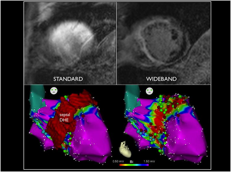
Standard MRI in upper left compared to wideband on upper right in a patient with hypertrophic cardiomyopathy, revealing significant septal and anterior wall scar, integrated with electroanatomical map on the bottom to guide substrate modification in real time.
In summary, the wideband LGE MRI is ready for widespread clinical use at specialized centers that have resources available to follow the appropriate MRI safety protocols. The wideband technique is expected to replace the standard LGE MRI with no increase in scan time, no change in imaging setup, minimal change in MRI safety profile and greatly improved image quality.
Limitations
The wideband protocol is specific for LGE-MRI, and does not overcome other types of image artifacts in cardiac cine images, which can be important for clinical interpretation of the images. The wideband protocol was done on one platform (Siemens, Malvern, PA), and the ability to incorporate this technique across a broad range of commercial systems is currently being tested. EAM was used to correlate MRI findings, and EAM is limited by tissue contact, the number of mapping points taken, and is operator dependent. Furthermore, epicardial fat is difficult to distinguish from scar, possibly overestimating scar size on the epicardium 11. We therefore only measured dense scar (<0.5mV) to calculate epicardial scar area, and our epicardial EAM scars were smaller than those measured on MRI, although only 4 scars were compared in Figure 5. Similar findings in a porcine model suggested that MRI correlates better with dense scar than border zone plus dense scar 16. Lastly, our study is a small clinical study with only 18 patients. A larger multi-center study is clearly warranted to confirm our findings and to appropriately identify specific patient groups most likely to benefit from this technique.
With regard to device safety, ICD interrogations were performed before and after MRI without systematic recording of device parameters into the electronic medical record. Although no significant changes in lead characteristics and device measurements were observed in all patients, specific quantification of lead thresholds and impedances could not be reported in this cohort.
When comparing the correlation between scar size on MRI and EAM, important differences in spatial resolution should be acknowledged. The spatial resolution of MRI at 8mm slices (1.4×1.9mm) is smaller than a mapping electrode, where a bipole of 2mm with 2 mm inter-electrode spacing contains the electrical signal of up to 6mm edge-to-edge. In addition, the standard interpolation setting of EAM is 15 mm, which is larger than a representative slice on MRI. These discrepancies may result in an overestimation of scar on EAM compared to MRI. Although higher mapping density is performed at border zones to improve the scar contour definition, the variability due to operator and ease of catheter access exists between cases.
Conclusions
The majority of patients referred for VT ablation have ICDs, which obscure the image quality of LGE-MRI. A novel wideband LGE MRI artifact correction protocol to image ventricular scar is clinically safe and feasible. Reduction and/or removal of ICD generator artifact improve the ability to visualize myocardium for clinical interpretation, which correlated well with EAM findings during VT ablation.
Acknowledgments
Funding: Research reported in this publication was supported by the National Heart, Lung, and Blood Institute of the National Institutes of Health under Award Number R21HL118533. The content is solely the responsibility of the authors and does not necessarily represent the official views of the National Institutes of Health.
Footnotes
Conflict of interest: Dr. Hu has a patent pending regarding the technologies used in this study.
Publisher's Disclaimer: This is a PDF file of an unedited manuscript that has been accepted for publication. As a service to our customers we are providing this early version of the manuscript. The manuscript will undergo copyediting, typesetting, and review of the resulting proof before it is published in its final citable form. Please note that during the production process errors may be discovered which could affect the content, and all legal disclaimers that apply to the journal pertain.
References
- 1.Simonetti OP, Kim RJ, Fieno DS, et al. An improved MR imaging technique for the visualization of myocardial infarction. Radiology. 2001 Jan;218:215–223. doi: 10.1148/radiology.218.1.r01ja50215. [DOI] [PubMed] [Google Scholar]
- 2.Tian J, Ahmad G, Mesubi O, Jeudy J, Dickfeld T. Three-dimensional delayed-enhanced cardiac MRI reconstructions to guide ventricular tachycardia ablations and assess ablation lesions. Circulation Arrhythmia and electrophysiology. 2012 Apr;5:e31–35. doi: 10.1161/CIRCEP.111.968636. [DOI] [PubMed] [Google Scholar]
- 3.Kalin R, Stanton MS. Current clinical issues for MRI scanning of pacemaker and defibrillator patients. Pacing and clinical electrophysiology: PACE. 2005 Apr;28:326–328. doi: 10.1111/j.1540-8159.2005.50024.x. [DOI] [PubMed] [Google Scholar]
- 4.Roguin A, Schwitter J, Vahlhaus C, et al. Magnetic resonance imaging in individuals with cardiovascular implantable electronic devices. Europace: European pacing, arrhythmias, and cardiac electrophysiology journal of the working groups on cardiac pacing, arrhythmias, and cardiac cellular electrophysiology of the European Society of Cardiology. 2008 Mar;10:336–346. doi: 10.1093/europace/eun021. [DOI] [PubMed] [Google Scholar]
- 5.Dickfeld T, Tian J, Ahmad G, et al. MRI-Guided ventricular tachycardia ablation: integration of late gadolinium-enhanced 3D scar in patients with implantable cardioverter-defibrillators. Circulation Arrhythmia and electrophysiology. 2011 Apr;4:172–184. doi: 10.1161/CIRCEP.110.958744. [DOI] [PubMed] [Google Scholar]
- 6.Sasaki T, Hansford R, Zviman MM, et al. Quantitative assessment of artifacts on cardiac magnetic resonance imaging of patients with pacemakers and implantable cardioverter-defibrillators. Circulation Cardiovascular imaging. 2011 Nov;4:662–670. doi: 10.1161/CIRCIMAGING.111.965764. [DOI] [PMC free article] [PubMed] [Google Scholar]
- 7.Rashid S, Rapacchi S, Vaseghi M, et al. Improved late gadolinium enhancement MRI for patients with implanted cardiac devices. Radiology. 2013 doi: 10.1148/radiol.13130942. Epub ahead of print. [DOI] [PMC free article] [PubMed] [Google Scholar]
- 8.Nazarian S, Halperin HR. How to perform magnetic resonance imaging on patients with implantable cardiac arrhythmia devices. Heart rhythm: the official journal of the Heart Rhythm Society. 2009 Jan;6:138–143. doi: 10.1016/j.hrthm.2008.10.021. [DOI] [PubMed] [Google Scholar]
- 9.Sosa E, Scanavacca M, d'Avila A, Pilleggi F. A new technique to perform epicardial mapping in the electrophysiology laboratory. Journal of cardiovascular electrophysiology. 1996 Jun;7:531–536. doi: 10.1111/j.1540-8167.1996.tb00559.x. [DOI] [PubMed] [Google Scholar]
- 10.Tung R, Nakahara S, Maccabelli G, et al. Ultra high-density multipolar mapping with double ventricular access: a novel technique for ablation of ventricular tachycardia. Journal of cardiovascular electrophysiology. 2011 Jan;22:49–56. doi: 10.1111/j.1540-8167.2010.01859.x. [DOI] [PubMed] [Google Scholar]
- 11.Tung R, Nakahara S, Ramirez R, Lai C, Fishbein MC, Shivkumar K. Distinguishing epicardial fat from scar: analysis of electrograms using high-density electroanatomic mapping in a novel porcine infarct model. Heart rhythm: the official journal of the Heart Rhythm Society. 2010 Mar;7:389–395. doi: 10.1016/j.hrthm.2009.11.023. [DOI] [PMC free article] [PubMed] [Google Scholar]
- 12.Nazarian S, Hansford R, Roguin A, et al. A prospective evaluation of a protocol for magnetic resonance imaging of patients with implanted cardiac devices. Annals of internal medicine. 2011 Oct 4;155:415–424. doi: 10.7326/0003-4819-155-7-201110040-00004. [DOI] [PMC free article] [PubMed] [Google Scholar]
- 13.Nazarian S, Roguin A, Zviman MM, et al. Clinical utility and safety of a protocol for noncardiac and cardiac magnetic resonance imaging of patients with permanent pacemakers and implantable-cardioverter defibrillators at 1.5 tesla. Circulation. 2006 Sep 19;114:1277–1284. doi: 10.1161/CIRCULATIONAHA.105.607655. [DOI] [PMC free article] [PubMed] [Google Scholar]
- 14.Sommer T, Naehle CP, Yang A, et al. Strategy for safe performance of extrathoracic magnetic resonance imaging at 1.5 tesla in the presence of cardiac pacemakers in non-pacemaker-dependent patients: a prospective study with 115 examinations. Circulation. 2006 Sep 19;114:1285–1292. doi: 10.1161/CIRCULATIONAHA.105.597013. [DOI] [PubMed] [Google Scholar]
- 15.Dong J, Calkins H, Solomon SB, et al. Integrated electroanatomic mapping with three-dimensional computed tomographic images for real-time guided ablations. Circulation. 2006 Jan 17;113:186–194. doi: 10.1161/CIRCULATIONAHA.105.565200. [DOI] [PubMed] [Google Scholar]
- 16.Nakahara S, Vaseghi M, Ramirez RJ, et al. Characterization of myocardial scars: electrophysiological imaging correlates in a porcine infarct model. Heart Rhythm. 2011 Jul;8:1060–1067. doi: 10.1016/j.hrthm.2011.02.029. [DOI] [PubMed] [Google Scholar]