Abstract
Quadrature coils are often desired in MR applications because they can improve MR sensitivity and also reduce excitation power. In this work, we propose, for the first time, a quadrature array design strategy for parallel transmission at 298 MHz using single-feed circularly polarized (CP) patch antenna technique. Each array element is a nearly square ring microstrip antenna and is fed at a point on the diagonal of the antenna to generate quadrature magnetic fields. Compared with conventional quadrature coils, the single-feed structure is much simple and compact, making the quadrature coil array design practical. Numerical simulations demonstrate that the decoupling between elements is better than –35 dB for all the elements and the RF fields are homogeneous with deep penetration and quadrature behavior in the area of interest. Bloch equation simulation is also performed to simulate the excitation procedure by using an 8-element quadrature planar patch array to demonstrate its feasibility in parallel transmission at the ultrahigh field of 7 Tesla.
Keywords: Patch antenna array, quadrature, circularly polarized (CP), parallel transmission
Introduction
The multi-element RF transmit or transceiver arrays (1-14) have been used to improve the transmit efficiency and parallel excitation performance for MR imaging at high and ultrahigh field fields. In this work, we propose and investigate a quadrature transmit array design strategy by using single-feed circularly polarized (CP) patch antennas (15) as the RF source. It is known that use of quadrature RF coils can improve MR sensitivity by up to 41% and reduce the required excitation power by half compared with linear RF coils, therefore, they are often desired in MR imaging. However, the conventional quadrature coils with two feeding ports are geometrically cumbersome, and extremely difficult to cooperate in building RF coil arrays. In addition, the conventional quadrature coil designs show difficulties in achieving sufficient electromagnetic decoupling in an array, particularly at ultrahigh magnetic fields. Because of these technical difficulties, such quadrature coil arrays for parallel excitation currently are not readily available. It has been demonstrated that with appropriate design, a single-feed microstrip patch antenna is able to generate CP magnetic fields (16,17). The single-feed patch antenna has a very simple structure, geometrically similar to a conventional linear surface coil, and thus can be easily used for building quadrature RF coil arrays for parallel transmission (18-37), making the design of quadrature coil arrays practical. Another merit of the patch antennas using the microstrip design (7,8,13,14,38,39) is their confined magnetic fields which provide the improved element decoupling in a coil array. To validate the feasibility of the quadrature transmit array design using the single-feed CP patch antennas, an 8-element planar transmit patch array was designed and modeled at 298 MHz (the proton Larmor frequency at the ultrahigh field of 7 Tesla) and the corresponding RF field distributions, element decoupling performance, and excitation accuracy when used for parallel excitation, were investigated. The numerical calculation was implemented by using Finite-Difference Time-Domain (FDTD) method (40-42) while the excitation accuracy was evaluated by simulating the Bloch Equation (43,44).
Theory and methods
The structure of 8-element quadrature patch array is shown in Figure 1. Each element was built as a nearly square ring microstrip patch antenna (15) using copper tape. The outer dimension of the ring was 12.2 cm by 12 cm, while the square slot cut was with side length of 4.4 cm. This square cutting was used to increase the path length of the surface current so as to reduce the resonant frequency to 298 MHz. This nearly square ring structure is able to generate two orthogonal modes, leading to a CP field (15). The coaxial feed port (blue points in Figure 1) was along the diagonal and very close to the square slot. The eight patch elements were equispaced distributed on the substrate and the distance between the neighboring elements was 4 cm. The ground was a copper sheet placed on the bottom of the substrate which was a piece of 6 mm thick TMM 13I material with permittivity of 13.1 (Rogers Corp., Chandler, AZ). The FDTD method was used to model this 8-element quadrature patch array, calculate the reflection and transmission parameters and evaluate the magnetic field distribution. The Yee cell size was 1 mm on three directions. The boundary condition was set as Perfectly Matching Layers (PML). The Gauss waveform was used to determine the exact frequency of the antenna array while then the Sinusoid waveform was used to calculate the RF field distribution. The stop criteria were set as the calculation converged to –30 dB. The FDTD simulation was performed by using the software XFDTD 6.4 (Remcom Inc.) on a Dell workstation with 2.33 GHz CPU. The total computation time for each setup was around ten hours. Given the size and geometry, this planar design could be potentially used for human spine imaging.
Figure 1.
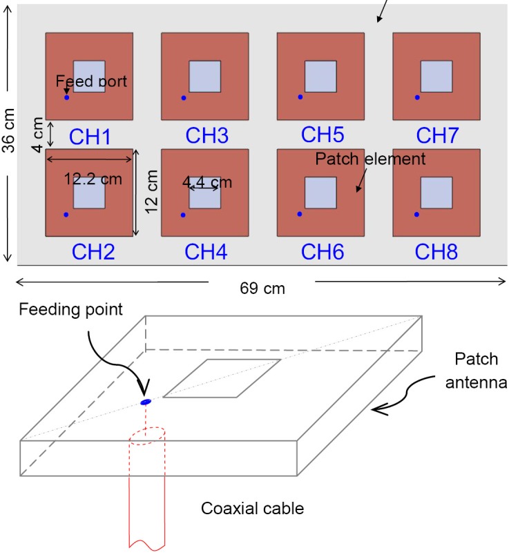
The prototype of the 8-element planar patch array and the physical structure of the patch antenna.
To demonstrate the transmission performance of the proposed single-feed patch antenna array, an example of parallel transmission was simulated by solving the Bloch equation. The desired excitation target is a 2-dimensional cylinder with 4 cm diameter on X-Y plane. The desired pattern was then excited using the 8-element patch antenna array at the reduction factor of 4. A constant density spiral trajectory with six turns was used in this simulation, the k-space extension was 0.5 cycle/cm. The eight RF pulses for the eight array elements were designed by using the spatial domain method (16,17), and then the Bloch equation was solved to simulate the excitation procedure to obtain the actual excitation pattern.
Results
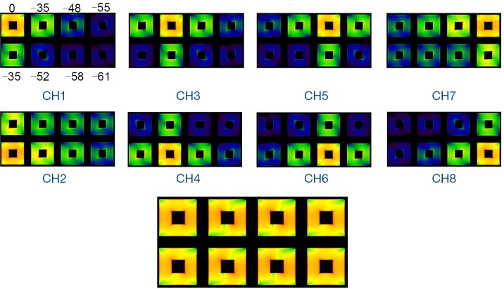
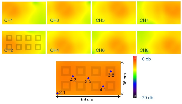
The simulated reflection coefficient S11 and the transmission coefficients S21 to S81 are plotted in Figure 2. At 298 MHz the S11 is –8 dB and the S21 to S81 are all better than –35 dB. Also, the S11 of a single patch coil is plotted in Figure 2C where the shape is almost identical to that of Figure 2A. All these demonstrate excellent decoupling between patch elements. Figure 3 demonstrates the current distribution on each patch antenna when individually excited, further proved the decoupling performance between the elements. Figure 4 shows the B1 field distribution of coronal plane at 10 cm above the array. The eight individual B1 profiles are shown when driving independently, each with good sensitivity pattern. Their combined B1 field has a homogeneous distribution when driving simultaneously. The axial and sagittal planes shown in Figure 5 demonstrate that the penetration of the patch array can reach 35 cm depth in unloaded case. The input RF power was normalized to 1 Watt. The average B1 at 5 mm above array surface is 3.2×10⁻⁶ Tesla while that at 35 cm depth is 2.2×10⁻⁷ Tesla, which is 7% of the field strength at 5 mm position. The B1 field is a CP magnetic field as can be seen from Figure 6, in which the B1 rotates with the time in one period.
Figure 2.
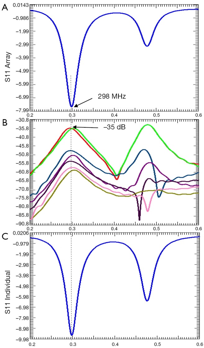
XFDTD plots of (A) simulated S11 of the array; (B) simulated S21 to S81 parameters between port 1 and the other 7 ports; (C) simulated S11 of a single patch coil (non-array).
Figure 3.
The current distribution on each patch antenna when individually excited, demonstrating excellent decoupling performance. The numbers on the first element denotes the relative current strength (dB) at the same feed power.
Figure 4.
The individual B1 fields of eight elements and their combined B1 field of the coronal plane at 10 cm above array surface. The blue points denote the B1 field strength and the unit is mGauss. The net input power is normalized to 1 Watt.
Figure 5.
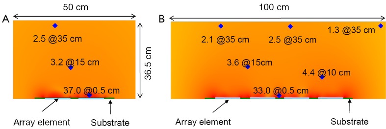
(A) Sagittal plane and (B) axial plane of the B1 field near the center of the patch array. The blue points denote the B1 field strength and the unit is mGauss. The net input power is normalized to 1 Watt.
Figure 6.

Circularly polarized (CP) magnetic field varies with time. t1-t8 denote eight discrete time point within one period, indicating quadrature or CP behavior of the patch array.
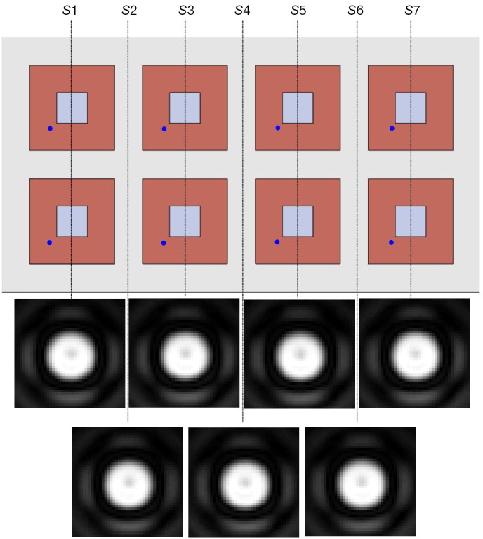
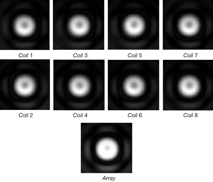
Figure 7 shows the excitation profiles at seven different positions along Z-direction of the planar array. Due to the different RF field distribution along the Z-direction, the performance of the parallel transmission was different. Figure 7 demonstrate it is feasible to perform parallel transmission by using the patch array at any slice along the array, and there was no obvious difference between the excitation profiles of each slice. Figure 8 shows the excitation profile of each array element for Slice 1 (S1 in Figure 7), demonstrating its feasibility to perform parallel transmission.
Figure 7.
Parallel transmission simulation results: the excitation profiles at different Z-positions by using the patch antenna array. Although the RF field distribution of each element varies along the Z-direction, the excitation profiles at different positions along Z-direction were nearly same as the target profile.
Figure 8.
The excitation profile of the first slice and the individual excitation patterns of the eight patch array elements.
Discussion and conclusions
In this work, a novel design of quadrature planar array is proposed using the nearly square ring microstrip patch antenna technique. Compared with the conventional quadrature coils, the structure of CP patch antennas is much simple, which makes design of quadrature coil arrays practical. From the FDTD simulation results it can be seen that the field penetration of patch antennas is comparable to traditional loop coils. In addition, each array element has sufficient field diversity. As such, this quadrature array design using single-feed circular polarized patch antennas is feasible and advantageous for parallel transmission. In a square-ring type patch antenna, its resonance frequency varies with the size of the patch antenna. Any feeding point along the diagonal of single-feed patch antenna could generate CP fields but their input impedance varies. Therefore, in practical designs of CP square ring patch antennas, the ring size and the position of the feed point are critical to the performance of the quadrature coil array and should be appropriately chosen.
Acknowledgements
This work was partially supported by NIH grants EB004453, EB008699, K99EB015487 and P41 EB013598, a QB3 Research Award, a Springer Med Fund Award, and a National Natural Science Foundation of China Grant (51228702).
Disclosure: The authors declare no conflict of interest.
References
- 1.Roemer PB, Edelstein WA, Hayes CE, et al. The NMR phased array. Magn Reson Med 1990;16:192-225 [DOI] [PubMed] [Google Scholar]
- 2.Kraff O, Bitz AK, Kruszona S, et al. An eight-channel phased array RF coil for spine MR imaging at 7 T. Invest Radiol 2009;44:734-40 [DOI] [PubMed] [Google Scholar]
- 3.Wu B, Wang C, Krug R, et al. 7T human spine imaging arrays with adjustable inductive decoupling. IEEE Trans Biomed Eng 2010;57:397-403 [DOI] [PMC free article] [PubMed] [Google Scholar]
- 4.Adriany G, Van de Moortele PF, Wiesinger F, et al. Transmit and receive transmission line arrays for 7 Tesla parallel imaging. Magn Reson Med 2005;53:434-45 [DOI] [PubMed] [Google Scholar]
- 5.Li Y, Xie Z, Pang Y, et al. ICE decoupling technique for RF coil array designs. Med Phys 2011;38:4086-93 [DOI] [PMC free article] [PubMed] [Google Scholar]
- 6.Wu B, Wang C, Kelley DA, et al. Shielded microstrip array for 7T human MR imaging. IEEE Trans Med Imaging 2010;29:179-84 [DOI] [PMC free article] [PubMed] [Google Scholar]
- 7.Wu B, Wang C, Lu J, et al. Multi-channel microstrip transceiver arrays using harmonics for high field MR imaging in humans. IEEE Trans Med Imaging 2012;31:183-91 [DOI] [PMC free article] [PubMed] [Google Scholar]
- 8.Zhang X, Ugurbil K, Chen W.A microstrip transmission line volume coil for human head MR imaging at 4T. J Magn Reson 2003;161:242-51 [DOI] [PubMed] [Google Scholar]
- 9.Boskamp EB, Lee RF. Whole Body LPSA transceive array with optimized transmit homogeneity. Proceedings of International Society of Magnetic Resonance in Medicine, Honolulu, HI, 2002:903. [Google Scholar]
- 10.Pang Y, Xie Z, Xu D, et al. A dual-tuned quadrature volume coil with mixed λ/2 and λ/4 microstrip resonators for multinuclear MRSI at 7 T. Magn Reson Imaging 2012;30:290-8 [DOI] [PMC free article] [PubMed] [Google Scholar]
- 11.Pang Y, Zhang X, Xie Z, et al. Common-mode differential-mode (CMDM) method for double-nuclear MR signal excitation and reception at ultrahigh fields. IEEE Trans Med Imaging 2011;30:1965-73 [DOI] [PMC free article] [PubMed] [Google Scholar]
- 12.Vaughan JT, Adriany G, Snyder CJ, et al. Efficient high-frequency body coil for high-field MRI. Magn Reson Med 2004;52:851-9 [DOI] [PubMed] [Google Scholar]
- 13.Wu B, Zhang X, Wang C, et al. Flexible transceiver array for ultrahigh field human MR imaging. Magn Reson Med 2012;68:1332-8 [DOI] [PMC free article] [PubMed] [Google Scholar]
- 14.Zhang X, Ugurbil K, Sainati R, et al. An inverted-microstrip resonator for human head proton MR imaging at 7 tesla. IEEE Trans Biomed Eng 2005;52:495-504 [DOI] [PubMed] [Google Scholar]
- 15.Garg R eds. Microstrip Antenna Design Handbook. Artech House, 2001.
- 16.Zhang X, Wang C. Single-feed quadrature coils as transceiver array elements for improved SNR and transmit efficiency. Proceedings of International Society of Magnetic Resonance in Medicine, Honolulu, HI, 2009:3014. [Google Scholar]
- 17.Pang Y, Wang C, Zhang X. Design and numerical evaluation of an 8-element quadrature transceiver array using single-feed CP patch antenna for parallel reception and excitation. Proceedings of International Society of Magnetic Resonance in Medicine, Stockholm, 2010:3804.
- 18.Zhu Y.Parallel excitation with an array of transmit coils. Magn Reson Med 2004;51:775-84 [DOI] [PubMed] [Google Scholar]
- 19.Katscher U, Börnert P.Parallel RF transmission in MRI. NMR Biomed 2006;19:393-400 [DOI] [PubMed] [Google Scholar]
- 20.Katscher U, Börnert P, Leussler C, et al. Transmit SENSE. Magn Reson Med 2003;49:144-50 [DOI] [PubMed] [Google Scholar]
- 21.Grissom W, Yip CY, Zhang Z, et al. Spatial domain method for the design of RF pulses in multicoil parallel excitation. Magn Reson Med 2006;56:620-9 [DOI] [PubMed] [Google Scholar]
- 22.Pang Y, Zhang X.Precompensation for mutual coupling between array elements in parallel excitation. Quant Imaging Med Surg 2011;1:4-10 [DOI] [PMC free article] [PubMed] [Google Scholar]
- 23.Feng S, Ji J. A novel fast algorithm for parallel excitation: pulse design in MRI. Conf Proc IEEE Eng Med Biol Soc 2012;2012:1102-5. [DOI] [PubMed]
- 24.Han H, Song AW, Truong TK. Integrated parallel reception, excitation, and shimming (iPRES). Magn Reson Med 2013;70:241-7 [DOI] [PMC free article] [PubMed] [Google Scholar]
- 25.Lee D, Lustig M, Grissom WA, et al. Time-optimal design for multidimensional and parallel transmit variable-rate selective excitation. Magn Reson Med 2009;61:1471-9 [DOI] [PMC free article] [PubMed] [Google Scholar]
- 26.Poser BA, Anderson RJ, Guérin B, et al. Simultaneous multislice excitation by parallel transmission. Magn Reson Med. 2013 doi: 10.1002/mrm.24791. [Epub ahead of print] [DOI] [PMC free article] [PubMed] [Google Scholar]
- 27.Schmitter S, DelaBarre L, Wu X, et al. Cardiac imaging at 7 Tesla: Single- and two-spoke radiofrequency pulse design with 16-channel parallel excitation. Magn Reson Med 2013;70:1210-9 [DOI] [PMC free article] [PubMed] [Google Scholar]
- 28.Setsompop K, Alagappan V, Zelinski AC, et al. High-flip-angle slice-selective parallel RF transmission with 8 channels at 7 T. J Magn Reson 2008;195:76-84 [DOI] [PMC free article] [PubMed] [Google Scholar]
- 29.Yoon D, Fessler JA, Gilbert AC, et al. Fast joint design method for parallel excitation radiofrequency pulse and gradient waveforms considering off-resonance. Magn Reson Med 2012;68:278-85 [DOI] [PMC free article] [PubMed] [Google Scholar]
- 30.Grissom WA, Kerr AB, Stang P, et al. Minimum envelope roughness pulse design for reduced amplifier distortion in parallel excitation. Magn Reson Med 2010;64:1432-9 [DOI] [PMC free article] [PubMed] [Google Scholar]
- 31.Heilman JA, Derakhshan JD, Riffe MJ, et al. Parallel excitation for B-field insensitive fat-saturation preparation. Magn Reson Med 2012;68:631-8 [DOI] [PMC free article] [PubMed] [Google Scholar]
- 32.Jesmanowicz A, Nencka AS, Li SJ, et al. Two-axis acceleration of functional connectivity magnetic resonance imaging by parallel excitation of phase-tagged slices and half k-space acceleration. Brain Connect 2011;1:81-90 [DOI] [PMC free article] [PubMed] [Google Scholar]
- 33.Kirilina E, Kühne A, Lindel T, et al. Current CONtrolled Transmit And Receive Coil Elements (CONTAR) for Parallel Acquisition and Parallel Excitation Techniques at High-Field MRI. Appl Magn Reson 2011;41:507-23 [DOI] [PMC free article] [PubMed] [Google Scholar]
- 34.Ma C, Xu D, King KF, et al. Perturbation analysis of the effects of B1+ errors on parallel excitation in MRI. Conf Proc IEEE Eng Med Biol Soc 2009;2009:4064-6. [DOI] [PubMed]
- 35.Ma C, Xu D, King KF, et al. Joint design of spoke trajectories and RF pulses for parallel excitation. Magn Reson Med 2011;65:973-85 [DOI] [PubMed] [Google Scholar]
- 36.Mei CS, Panych LP, Yuan J, et al. Combining two-dimensional spatially selective RF excitation, parallel imaging, and UNFOLD for accelerated MR thermometry imaging. Magn Reson Med 2011;66:112-22 [DOI] [PMC free article] [PubMed] [Google Scholar]
- 37.Rahbar H, Partridge SC, Demartini WB, et al. Improved B1 homogeneity of 3 Tesla breast MRI using dual-source parallel radiofrequency excitation. J Magn Reson Imaging 2012;35:1222-6 [DOI] [PMC free article] [PubMed] [Google Scholar]
- 38.Zhang X, Ugurbil K, Chen W.Microstrip RF surface coil design for extremely high-field MRI and spectroscopy. Magn Reson Med 2001;46:443-50 [DOI] [PubMed] [Google Scholar]
- 39.Zhang X, Zhu XH, Chen W. Higher-order harmonic transmission-line RF coil design for MR applications. Magn Reson Med 2005;53:1234-9 [DOI] [PubMed] [Google Scholar]
- 40.Collins CM, Liu W, Swift BJ, et al. Combination of optimized transmit arrays and some receive array reconstruction methods can yield homogeneous images at very high frequencies. Magn Reson Med 2005;54:1327-32 [DOI] [PubMed] [Google Scholar]
- 41.Collins CM, Wang Z, Mao W, et al. Array-optimized composite pulse for excellent whole-brain homogeneity in high-field MRI. Magn Reson Med 2007;57:470-4 [DOI] [PMC free article] [PubMed] [Google Scholar]
- 42.Wang Z, Lin JC, Vaughan JT, et al. Consideration of physiological response in numerical models of temperature during MRI of the human head. J Magn Reson Imaging 2008;28:1303-8 [DOI] [PMC free article] [PubMed] [Google Scholar]
- 43.Pauly J, Nishimura D, Macovski A.A k-space analysis of small-tip-angle excitation. 1989. J Magn Reson 2011;213:544-57 [DOI] [PubMed] [Google Scholar]
- 44.Pauly J, Nishimura D, Macovski A.A linear class of large-tip-angle selective excitation pulses. J Magn Reson 1989;82:571-87 [Google Scholar]


