Abstract
The patch-clamp technique is today the most well-established method for recording electrical activity from individual neurons or their subcellular compartments. Nevertheless, achieving stable recordings, even from individual cells, remains a time-consuming procedure of considerable complexity. Automation of many steps in conjunction with efficient information display can greatly assist experimentalists in performing a larger number of recordings with greater reliability and in less time. In order to achieve large-scale recordings we concluded the most efficient approach is not to fully automatize the process but to simplify the experimental steps and reduce the chances of human error while efficiently incorporating the experimenter's experience and visual feedback. With these goals in mind we developed a computer-assisted system which centralizes all the controls necessary for a multi-electrode patch-clamp experiment in a single interface, a commercially available wireless gamepad, while displaying experiment related information and guidance cues on the computer screen. Here we describe the different components of the system which allowed us to reduce the time required for achieving the recording configuration and substantially increase the chances of successfully recording large numbers of neurons simultaneously.
Keywords: Neuroscience, Issue 80, Patch-clamp, automatic positioning, whole-cell, neuronal recording, in vitro, multi-electrode
Introduction
The capacity to record and stimulate multiple sites with micrometer precision is extremely useful for experimentally achieving a better understanding of neuronal systems. Many techniques have been developed to this end but none allow the submillivolt resolution achieved by the patch-clamp technique, essential for studying subthreshold activity and individual postsynaptic potentials. Here we cover the development of a twelve-electrode computer-assisted patch-clamp system aimed at simultaneously recording and stimulating a large number of individual cells with sufficient precision for the study of neuronal connectivity. While many other applications can be conceived for such a system, it lends itself particularly well to the study of synaptic connectivity given that the number of possible connections within a group of neurons grows proportionally to the square of the number of neurons in question. Therefore, while a system with three electrodes allows testing the occurrence of up to six connections and most often recording a single one, recording twelve neurons allows testing the occurrence of up to 132 connections and frequently observing over one dozen (Figure 1). The observation of dozens of connections simultaneously makes it possible to analyze the organization of small networks and infer statistical properties of the network structure that cannot be probed otherwise1. Moreover, precise stimulation of numerous cells also allows the quantification of recruitment of postsynaptic cells2.
Protocol
1. Equipment Preparation
- Control manipulators from a computer
- Connect each micromanipulator controller box to a computer through serial ports (RS-232).
- Implement the commands for positioning, querying and adjusting settings to be sent via the serial port. Given speed and hardware compatibility issues C/C++ is recommended as the programming language.
- Standardize the reference system of the manipulators so that zero is the closest possible position with respect to the motors and positive movement is directed away from the motors.
- Position the microscope at its central position 2 mm above the specimen focal plane (coordinates [0, 0, 2000]).
- Store, for each manipulator, the local coordinates that allow the tip of a pipette to be observed in the center of the field of view of the microscope. This is the initial reference point for each electrode.
- Visualize electrode positions. It is very useful to be able to track the position of each electrode during an experiment. A graphical representation is the most intuitive way of accomplishing this. To that end the reference systems of each electrode and that of the microscope must be matched. A simple way to accomplish this is:
- Bring the tip of an electrode to the center of the field of view.
- Store the position on each axis of the manipulator and each axis of the microscope.
- Execute with the x-axis of the manipulator a relatively large movement (1 mm).
- Locate the tip once more moving only the microscope.
- Calculate the difference in the microscope position since it was last measured. These are the projections of the electrode axis movement onto the microscope axes.
- Repeat steps 2.3 - 2.5 for the Y and Z axes of the electrode manipulator. This allows a matrix of projections onto the microscope axes to be determined (Figure 2) also called cosine matrix:

- Invert this matrix to make it possible to calculate the movements, in three dimensions, required by the electrode manipulator to reach a given position in the microscope coordinate system:

- Using the initial reference point and the cosine matrix determine the position of each electrode in microscope coordinates.
- Display graphically, based on the microscope coordinates, the position of each electrode at regular intervals. We chose to use C/C++ drawing libraries (GDI+) to draw electrode positions every 40 msec.
- Repeat steps 1.2.1 - 1.2.7 every time manipulator angles are changed or if position changes of several millimeters are needed, for example, when the type of electrode is changed.
Enable storing the positions of relevant features in the tissue, such as cells or anatomical reference points, in microscope coordinates.
- Acquire video and overlay relevant information.
- Mechanically align the x-axis of motion of the microscope with the horizontal axis of the microscope camera.
- Install on the computer a framegrabber with live video and overlay capability and a software development kit (SDK).
- Implement live video display operation with the SDK.
- Convert the microscope coordinate system to the camera reference system by the appropriate translation and scaling.
- Draw the relevant features in camera coordinates and overlay on the live video the resulting image at regular intervals of about 40 msec (Figure 3).
- Control Amplifiers.
- Use the amplifier software to control the amplifier settings from the interface.
- Control oscilloscopes.
- Connect the oscilloscopes to the PC using serial ports.
- Determine the oscilloscope scale, coupling and temporal resolution for the different steps of the patch-clamp procedure in voltage-clamp (e.g. electrode in bath, seal formation, whole-cell configuration) and current-clamp.
- Send the appropriate oscilloscope setting commands whenever amplifier commands are issued from the interface.
- Control pipette pressure.
- Assemble a pressure control system according to Figure 4.
- Use a 12 V/5 V power supply to supply each electronic component appropriately.
- Connect the output of one membrane pump to the positive pressure buffer (a 100 ml container).
- Connect the input of one membrane pump to the negative pressure buffer (a 100 ml container).
- Connect the pipette holder tubing to a pressure sensor in the pressure control system and a pneumatic valve that connects to the main pressure compartment.
- Connect each of the pressure buffers to a valve connected to the main pressure compartment.
- Connect a valve between the main pressure compartment and the atmosphere.
- Connect a pressure sensor to the main pressure compartment.
- Connect a pressure sensor to each buffer.
- Connect the pressure control system to a data acquisition board.
- Connect each pressure sensor to one analog input.
- Connect each valve to a digital output.
- Remove atmospheric pressure offset from all sensors by opening all valves except those connecting to the membrane pumps and subtracting the measured pressure.
- Implement pressure control
- Define in the interface a control to activate or de-activate positive pressure control for each pipette.
- Define a minimal positive pressure for the pipettes of about 70 mbar.
- Periodically (every 0.5 sec) detect whenever pressure in pipettes under active pressure control drops below the set threshold.
- Upon threshold crossing open the positive pressure buffer to the main pressure compartment and this compartment towards the pipette in question during brief periods (20 msec) until pressure in the pipettes is above threshold. Close all other valves.
- De-activate further pressure control as the final approach towards a cell of interest is initiated.
- Apply negative pressure for seal formation
- Close all valves and open the negative pressure buffer valve towards the main pressure compartment and this compartment towards the pipette in question for the duration the experimenter requires by keeping a button pressed.
- Centralize commands onto a human interface device.
- Connect a commercially available wireless gamepad to the PC.
- Implement readout of joystick status. For instance, use the DirectX libraries for C/C++ to perform readouts every 5 msec.
- Compare current status with previous status to detect which buttons have been pressed, released or kept pressed since last time step.
- Assign functions to each button in the gamepad. An example of this mapping is shown in Figure 5.
2. Patch-clamp Procedure
Prepare the brain slices of the region of interest.
Place a brain slice of interest, with the region of interest in the center of the microscope's displacement range.
- Cell Selection
- Identify cells of interest by browsing with the microscope. Store the position of the cells based on the microscope coordinate system with a right mouse-click on the live video display on top of the cell of interest.
- The graphical interface will display the selected cells as well as the micropipettes for a global overview and software will add a marker on the cell position that will be overlaid on the images. Additionally an image of the cell is captured for future reference in the file 'Cell#.jpg'.
- Attribution of cells to pipettes
- After selecting the cells of interest, assign which pipette will record each cell. The graphical interface provides assignment controls that should be set. Visualize a preview of the final configuration by selecting the checkbox 'Show Final Positions'.
- Select each pipette for which the final position preview is desired or check the 'Select All' checkbox. Disable the current position display for better visualization if needed.
- Prepare the Pipettes
- Fill the pipettes (6 - 8 MΩ are usually best if many pipettes are used) with intracellular solution and load them into their holders. Place the headstages in their fixations but do not slide them forward to avoid touching the bath with the pipette tip.
- Enable the positive pressure control and select all pipettes to ensure that the tips will remain clean. Gently slide each headstage in place.
- Locating the pipette tips
- Position the microscope to a central position with focus 3 mm above the slice by pressing button R2 while holding button 'A'. Use the corresponding position for each manipulator as stored from the previous experiment by pressing button L2 while holding button A. Note: At this point there should be either a distinctive shadow of a pipette in view or a small movement along the pipette's axis should be enough to observe it in most cases. Compensation for the slight differences in pipette shape has to be performed manually.
- Bring the pipette tip into focus. Place the tip on the red central dot of the video display without moving the microscope (it should still be at position [0, 0, 2000]).
- Inform the software that the pipette is at the center of the display by pressing button Z while holding button C. After each pipette tip is located, send that pipette backwards so that the following one can be located by pressing button L1 while holding button A.
- Approaching the cells
- Once all pipette tips have been precisely located and each pipette is attributed to a cell, automatically position the pipettes close to their respective cells. Simply right-click in the center of the group of cells and select the option 'Cluster' on the popup menu. On the cluster options window that will appear, select all the pipettes that you want to position at this time and click on 'Go with all checked pipettes'. Repeat this operation for each cluster of cells of interest.
- Perform the final approach manually. The position of the pipettes relative to the cells can be specified differently but usually is simply 200 µm away from the cell in the axis of the pipette and 200 µm above it in the vertical direction, which is enough to keep the pipette's tip outside the tissue. Wait until the positioning of the pipettes is finished and move the microscope towards a pipette by pressing button R1 while holding button C.
- Recalibrate each pipette position by focusing the microscope on its tip anywhere in the video display and pressing button B while holding button C. A square grid should briefly appear indicating the identified position of the pipette. If the position is not correct, position the tip on the central dot of the video display and press button Z while holding button C.
- Establish the cell-attached configuration
- Confirm that the cell of interest for the current pipette is correctly marked. Otherwise move the microscope to match the cell of interest with the central red dot. Mark the cell by pressing button Y while holding button C. Press button L2 while holding button C to position the pipette 200 µm away from its assigned cell, the microscope will automatically move to the corresponding position.
- Adjust the pipette position so it matches the red dot. Adjust the pipette offset by pressing button R1 while holding button X.
- Activate the test pulse by pressing button L1 while holding button X. Slowly approach the pipette to its attributed cell.
- Upon observing the formation of a dimple on the surface of the cell's membrane apply a brief pulse of negative pressure by pressing button Y while holding button Z to allow the applied pressure to reach the cell. A holding potential of about -65mV should established at this point by pressing the button L2 while holding button X.
- Whole-cell configuration
- Once a Giga-seal is formed for each cell, start rupturing the membranes by applying negative pressure.
- Perform recordings
- Use the stimulation/acquisition system to perform your recordings. Apply pulses or trains of pulses on one individual cell at a time and observe responses on the remaining cells to map connectivity among the recorded cells.
- Recede pipettes
- Once recordings are finished, recede pipettes slowly from the tissue by right-clicking on the Table radio-button. Select 'Recede->Pipettes 500 µm' to have the pipettes recede a short distance along their axes. Observe the drift in potential of the cells (clearing the tips by applying some positive pressure may help).
- To recede pipettes all the way back, set the positioning speed to 'Fast' and repeat the same operation but choose the 'All' option. Remove the used pipettes by gently sliding out the headstages and unscrewing the pipettes from the holders. It is useful to avoid twisting the holders in their sockets since this might greatly interfere with the pipette tip position.
Representative Results
Following the methods described above we succeeded in performing whole-cell recording of up to twelve neurons simultaneously, nearly doubling the largest number of neurons simultaneously patch-clamped thus far. Examples of networks of direct synaptic connections between Pyramidal Neurons recorded in Layer V of the somatosensory cortex of rats are shown in Figure 6.
The determination of connection probability profiles as a function of inter-somatic distance for a given cell-type is a typical measurement of interest that can be performed efficiently with a multi-electrode patch-clamp system1. Recently photo-stimulation began to appear as an even more efficient means of obtaining such data3,4. Importantly, however, the data acquired with multi-electrode patch-clamp systems allows experimenters to obtain a more complete mapping of the network under study as well as high-resolution staining with intracellular diffused dyes. In multi-electrode patch-clamp experiments every cell can be recorded and stimulated, which is often not the case with other techniques such as photo-stimulation or calcium imaging. This feature allows experimenters to keep track of biases in connectivity, such as the high incidence of reciprocal connections, which cannot be measured otherwise. By stimulating and recording every studied neuron we showed that neurons are not only biased towards being reciprocally connected but also form clusters. The scale of our recordings also allowed us to observe that a higher connection probability existed among pairs of neurons that shared common neighbors, i.e. were both simultaneously connected to other individual neurons in the sampled network (Figure 7a). This observation was significant at every intersomatic distance bin of 50 mm (from 50 to 250 mm). We also observed pairs of neurons sharing many common neighbors occurred significantly more often than expected by chance (Figure 7b). Moreover, we detected an effect on connection probability according to the number of common neighbors shared by a given pair of neurons. The more common neighbors it shares the more likely a pair of neurons is to be interconnected (Figure 7c).
This tendency leads to the formation of groups of neurons that are more densely interconnected than average. Interestingly, highly interconnected groups of neurons not only exhibited more numerous connections but also, in average, stronger ones1. These findings led us to the conclusion that neocortical circuitry is not only organized in layers and columns but also into cell assemblies, i.e. groups of neurons sharing dense and strong synaptic interconnectivity as postulated by Donald Hebb several decades ago.
Other results of interest that can be achieved with multiple simultaneously patch-clamped neurons include the quantification of the recruitment of inhibition by supra-threshold activity in different numbers of excitatory cells2. A ubiquitous form of inhibition in the neocortex5 is mediated by Martinotti cells (Figures 8a and b, adapted from Berger et al.) which receive input from Pyramidal cells and integrate it in turn affecting, with some latency, other Pyramidal cells. We showed that, after brief bursts of spiking activity in as few as four Pyramidal Cells, every Pyramidal Cell in a local microcircuit receives this form of inhibition (Figures 8c, c, and f). We also showed that these inhibitory postsynaptic potentials tend to saturate when eight or more Pyramidal Cells are stimulated simultaneously (Figure 8E).
An overview of the system components can be seen in Figure 9. The software interface and hardware are shown in Figure 9a and b as well as the controller interface in Figure 9c guiding the electrodes towards cells for recording under microscope objective (Figure 9d).
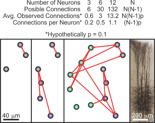 Figure 1. Calculation of the number of connections observed in an experiment as a function of the number of neurons simultaneously recorded shows a quadratic growth. Numerical calculations (top). Illustrative diagram where further neurons of the same network are successively added (bottom).
 Figure 2. Coordinate systems of each electrode manipulator (yellow) and microscope (red).
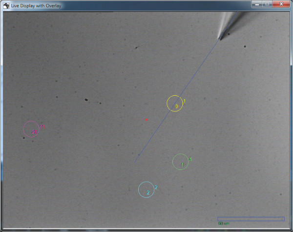 Figure 3. Screen capture of a pipette in approach towards assigned cell with overlaid approach vector, cell positions and scale bar.
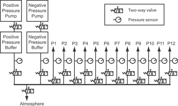 Figure 4. Diagram illustrating pneumatic system for pipette pressure control.
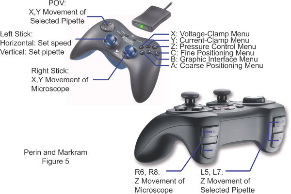 Figure 5. Commands on the human interface device that centralizes controls used during patch-clamp experiments.
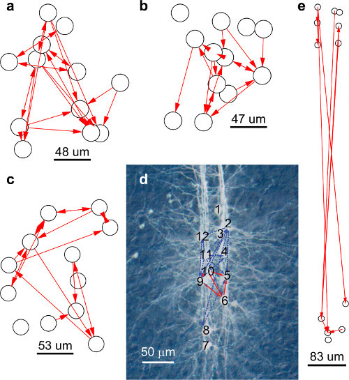 Figure 6. Example of three networks of direct synaptic connections mapped in individual experiments
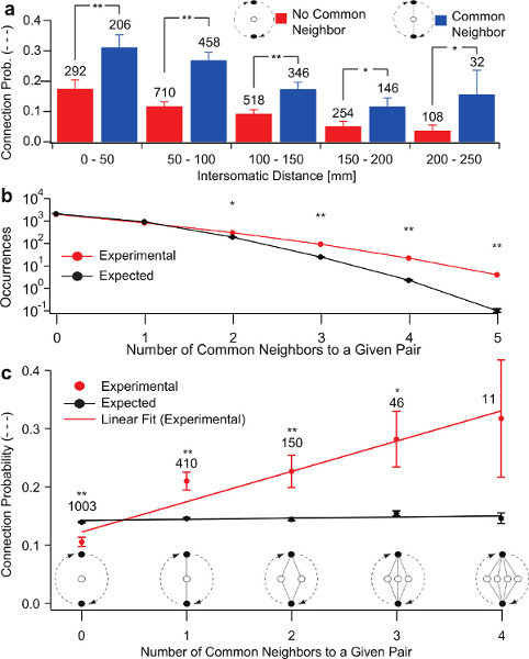 Figure 7. Common neighbor effect.(a) Pairs of neurons that simultaneously connect to at least one other neuron in the sampled network (blue) exhibit a significantly increased probability of being interconnected. (b) Pairs of neurons sharing multiple common neighbors occur more often than expected by chance in the sampled networks. (c) Connection probability within pairs of neurons increases as a function of the number of common neighbors shared by the pair.
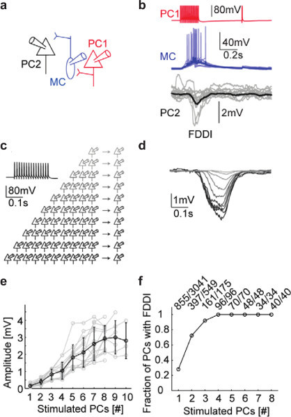 Figure 8. Quantification of the recruitment of Martinotti Cells.(a) Graphical representation of a Pyramidal Cell (red) that forms synapses onto a Martinotti Cell (blue) which in turn forms synapses onto a second Pyramidal Cell (black). (b) Supra-threshold stimulation of the Pyramidal cell (red) leads to recruitment of the Martinotti Cell (blue) through the integration of facilitating excitatory postsynaptic potentials. The Recruited Martinotti Cell then inhibits the second Pyramidal Cell (black). (c) Diagram representing the stimulation of increasing numbers of patch-clamped Pyramidal Cells and the effects on another Pyramidal Cell. (d) Average Inhibitory postsynaptic potentials recorded from a Pyramidal Cell as a function of the number of other nearby Pyramidal Cells that are stimulated. Adapted from Berger et al.2 (e) The amplitude of disynaptic inhibition in a local circuit tends to saturate when 9 or more Pyramidal Cells are stimulated indicating maximal recruitment of Martinotti Cells in probably reached at this point. (f) The fraction of cells receiving disynaptic inhibition quickly rises to 1 as increasing numbers of Pyramidal Cells are stimulated.
 Figure 9. Illustration of ensemble of the system.(a) Graphical user interface with main window, live video display, log window and graphical representation. (b) Microscope and manipulators. (c) Human interface device with controls for experimental procedure. (d) Glass micropipettes in position for recording multiple neurons.
 Figure 10. Binomial probability distribution functions that describe the fraction of experiments that successfully record a given number of cells given the use twelve electrodes. Comparison between the yield of experiments performed using visual feedback by experienced users are shown in blue and by less experienced users in non-ideal conditions in red.
Discussion
An immediate question usually arises concerning the rate of success of the procedure we described. For high success rates preparation is essential. Pipettes must have tip openings that are adequate for the cells beings recorded. Filtering the intracellular solution to avoid clogged pipettes is also important. Extremely clean, freshly pulled pipettes are another requirement. A binomial distribution is the simplest model that can be used to understand how these issues affect the final yield. It is reasonable to expect an experimenter with experience and proper equipment to achieve a success rate of 80% or more in recording individual neurons with visual feedback. Beginners can be expected to achieve much lower success rates, especially if important preparation steps are overlooked. How these rates translate in numbers of cells recorded per experiment can be seen in Figure 10. Further increases in the number of simultaneously patch-clamped neurons will likely require miniaturization of manipulators and increased reliability of the procedure, which in turn requires substantial attention to detail, but are entirely feasible.
The versatility of the system presented here is still being explored and novel applications have frequently been found, in particular in the exploration of the relationship between extracellular signals and individual neuron activity7. Anatomical considerations become more important as the distance between recorded cells increases. Nevertheless, this system definitely allows investigation of long-range and inter-layer connectivity wherever connections remain intact following the slicing procedure.
Micromanipulator control
Enabling automatic positioning with the micromanipulators greatly accelerates the process of multi-electrode patch-clamp and increases its reliability reducing the occurrence of human errors. Different manufacturers provide different solutions in order to establish a connection from the PC to the manipulators. A common option is a serial or USB port. In order to ensure fast communication we dedicated a serial port to each manipulator controller. The most useful feature of automatic positioning is probably the elimination of most lateral and vertical movement of electrodes inside the tissue and limiting its distortion. As the movement of the electrodes inside the tissue takes place almost exclusively along the axial direction, mechanical interference is minimized. Lateral movements are only necessary to occasionally avoid blood-vessels and cells.
Visualize electrode positions
It is very useful to be able to track the position of each electrode during an experiment. In a traditional setup losing sight of an electrode can quickly become problematic. When using a large number of electrodes it is not possible to keep all electrodes within the field of view at all times. Relying on a graphic representation is the most intuitive alternative and also assists in keeping track of the progress of the experiment, instantly showing which electrodes have already been positioned in their final configuration and which ones have not.
Video acquisition and overlay
The ability to display live video from the microscope field of view on an application window is very useful. The display window was programmed to respond to mouse clicks enabling storage of positions of interest (cell somata) as well as quick update of the relative positions between microscope and electrodes removing accumulated errors whenever they appear. We also implemented the overlay of practical information on live video such as the approach trajectory for each electrode towards chosen cells or the marking of these cells (Figure 3). Registration of features and superposition of auxiliary images such as figures from anatomical atlases was also implemented to assist where regions of interest are not immediately clear.
Amplifiers
Computer controlled microscope amplifiers may allow control to take place from other applications as well. This drastically increases the speed and reliability with which multiple cells can be recorded simultaneously and eliminates the major source of human errors. Following computer-assisted positioning and pipette pressure control this is the step that produces the most noticeable gains in time but the gains in reliability are even more important.
Oscilloscopes
Ensuring that test signals can be visualized in real time at the appropriate scale and temporal resolution greatly enhances the efficiency with which an experimenter can execute experimental steps. By coupling the oscilloscope settings to amplifier modes (such as current or voltage clamp) we ensured that time-critical steps were executed and visualized with little effort such as holding cells at appropriate membrane potentials immediately after achieving the cell attached configuration. Proper visualization was ensured by sending the appropriate scaling and coupling commands through the serial port in the oscilloscope's own protocol to fit the amplitude and offset of the test signals within the oscilloscope screen.
Pipette pressure control
As the number of electrodes employed in an experiment increases, ensuring that positive pressure is permanently applied to keep the tip of the glass electrodes clean becomes more demanding to the point of constituting an important hindrance. Sufficient positive and negative pressure (few hundreds of mbar) can be generated by simple membrane pumps. In order to stabilize the pressure, these pumps were coupled to reservoirs of approximately 100 ml whose opening and closing was controlled by pneumatic valves. The valves in turn were computer-controlled using a data acquisition card. The diagram of the pneumatic circuit can be seen in Figure 4. The pressure controller performs an important role not only ensuring pipette tips remain clean but also allowing the formation of Gigaohm seals quickly, upon the observation of dimples on the cell membrane as pipettes touch the cells, further accelerating the procedure.
The human interface device
Most experimental setups have the controls of experimental equipment widely dispersed over a large area. We concentrated the most commonly used controls on a single wireless gamepad (Figure 5) greatly reducing the time and effort required to record each cell but most importantly, eliminating sources of human error which can often bring large experiments to a premature end.
Programming language
We had very little choice in terms of the programming language for this application since the only language that supported integration of all the required equipment was C/C++. One great advantage of C/C++ is the possibility to implement multiple processing threads and fully profit from the performance improvement allowed by multiple-core processors.
Electrophysiological data acquisition
The system we described leaves the choice of electrophysiological recording software and data acquisition system up to the experimenter. Exchange of communications between data-acquisition software and our application can take place over serial ports or via socket communication over the network.
Future perspectives
More than 30 years since Sakmann and Neher's seminal experiments, the patch-clamp technique is still alone in providing data with a particular combination of signal resolution and sampling frequency that are required for a wide variety of experiments, in particular those involving the detection of individual post-synaptic currents or potentials. By developing a computer-assisted system that enables recording of many neurons simultaneously we aimed at expanding the experimental possibilities of the patch-clamp technique. Combination of such new possibilities with recent developments in experimental neuroscience8-13 can open the way towards a more profound understanding of neuronal circuits with unprecedented speed and detail.
Disclosures
The authors declare that they have no competing financial interests.
Acknowledgments
We would like to thank Gilad Silberberg, Michele Pignatelli, Thomas K. Berger, Luca Gambazzi, and Sonia Garcia for valuable advice on improvements for the patch-clamp procedure automation. We thank Rajnish Ranjan for valuable advice and assistance with software implementation. This work was funded in part by the EU Synapse project and partly by the Human Frontiers Science Program.
References
- Perin R, Berger TK, Markram H. A synaptic organizing principle for cortical neuronal groups. Proc. Natl. Acad. Sci. U.S.A. 2011;108:5419–5424. doi: 10.1073/pnas.1016051108. [DOI] [PMC free article] [PubMed] [Google Scholar]
- Berger TK, Silberberg G, Perin R, Markram H. Brief Bursts Self-Inhibit and Correlate the Pyramidal Network. PLoS Biol. 2010;8:e1000473. doi: 10.1371/journal.pbio.1000473. [DOI] [PMC free article] [PubMed] [Google Scholar]
- Fino E, Yuste R. Dense inhibitory connectivity in neocortex. Neuron. 2011;69:1188–1203. doi: 10.1016/j.neuron.2011.02.025. [DOI] [PMC free article] [PubMed] [Google Scholar]
- Packer AM, Yuste R. Dense, Unspecific Connectivity of Neocortical Parvalbumin-Positive Interneurons: A Canonical Microcircuit for Inhibition. J. Neurosci. 2011;31:13260–13271. doi: 10.1523/JNEUROSCI.3131-11.2011. [DOI] [PMC free article] [PubMed] [Google Scholar]
- Berger TK, Perin R, Silberberg G, Markram H. Frequency-dependent disynaptic inhibition in the pyramidal network: a ubiquitous pathway in the developing rat neocortex. J. Physiol. 2009;587:5411–5425. doi: 10.1113/jphysiol.2009.176552. [DOI] [PMC free article] [PubMed] [Google Scholar]
- Kodandaramaiah SB, Franzesi GT, Chow BY, Boyden ES, Forest CR. Automated whole-cell patch-clamp electrophysiology of neurons in vivo. Nat. Methods. 2012;9:585–587. doi: 10.1038/nmeth.1993. [DOI] [PMC free article] [PubMed] [Google Scholar]
- Anastassiou CA, Perin R, Markram H, Koch C. Ephaptic coupling of cortical neurons. Nat. Neurosci. 2011;14:217–223. doi: 10.1038/nn.2727. [DOI] [PubMed] [Google Scholar]
- Prakash R, et al. Two-photon optogenetic toolbox for fast inhibition, excitation and bistable modulation. Nat. Methods. 2012;9:1171–1179. doi: 10.1038/nmeth.2215. [DOI] [PMC free article] [PubMed] [Google Scholar]
- Papagiakoumou E, et al. Scanless two-photon excitation of channelrhodopsin-2. Nat Methods. 2010;7:848–854. doi: 10.1038/nmeth.1505. [DOI] [PMC free article] [PubMed] [Google Scholar]
- Ko H, et al. Functional specificity of local synaptic connections in neocortical networks. Nature. 2011;473:87–91. doi: 10.1038/nature09880. [DOI] [PMC free article] [PubMed] [Google Scholar]
- Wickersham IR, et al. Monosynaptic Restriction of Transsynaptic Tracing from Single, Genetically Targeted Neurons. Neuron. 2007;53:639–647. doi: 10.1016/j.neuron.2007.01.033. [DOI] [PMC free article] [PubMed] [Google Scholar]
- Liang CW, Mohammadi M, Santos MD, Tang C-M. Patterned Photostimulation with Digital Micromirror Devices to Investigate Dendritic Integration Across Branch Points. J. Vis. Exp. 2011. p. e2003. [DOI] [PMC free article] [PubMed]
- Nikolenko V, et al. SLM Microscopy: Scanless Two-Photon Imaging and Photostimulation with Spatial Light Modulators. Front Neural Circuits. 2008;2 doi: 10.3389/neuro.04.005.2008. [DOI] [PMC free article] [PubMed] [Google Scholar]


