

Abstract
This paper presents the kinematic design of a single degree-of-freedom exoskeleton mechanism: a planar eight-bar mechanism for finger curling. The mechanism is part of a finger-thumb robotic device for hand therapy that will allow users to practice key pinch grip and finger-thumb opposition, allowing discrete control inputs for playing notes on a musical gaming interface. This approach uses the mechanism to generate the desired grasping trajectory rather than actuating the joints of the fingers and thumb independently. In addition, the mechanism is confined to the back of the hand, so as to allow sensory input into the palm of the hand, minimal size and apparent inertia, and the possibility of placing multiple mechanisms side-by-side to allow control of individual fingers.
I. Introduction
Over the past several decades, robotic devices have emerged as a promising tool for both administering and investigating rehabilitation after stroke. For an introduction to this research topic, see [1], [2]. There are two often referenced advantages when developing robotic devices for administering therapy: automating the repetitive and strenuous aspects of physical therapy and delivering it in a highly repeatable manner. As a scientific investigation tool, robotic devices offer a second set of advantages: the ability to quantify recovery progress with a wide variety of performance metrics (strength, range-of-motion, etc.) and to test and compare therapy paradigms.
A wide variety of assistive control strategies have been developed (see review: [3]) including robots that rigidly follow fixed paths, robots that assist only if patient performance failure is detected, and soft robots that form a model of the patient’s weakness. Implementations of these control strategies have produced a large body of clinical evidence that suggests that exercise with robotic therapy device can benefit, albeit modestly, stroke patients (see reviews [4], [5], [6]). However, it is still unclear what factors directly promote recovery. It is therefore crucial to more clearly identify the recovery mechanisms present in robotic therapy and how these mechanisms may be optimized to increase recovery gains.
Two key factors that are thought to influence motor recovery during physical therapy are the intensity of motor output (subject voluntary participation) and the intensity of movement-correlated sensory information (from movement completion). In a robotic therapy device, these two factors may be in conflict. If the robot completes therapy movements independent of patient output, then motor output may be reduced, but if the subject cannot complete the movement without assistance, then the correlated sensory information is limited. To address this problem we previously developed an assist-as needed control algorithm [7] that allows the effort of the patient to be modulated while maintaining the kinematics of movement performance within close bounds to a specified desired movement. This allows neuromuscular motor control output and afference to be independently controlled. One limitation with the previous implementation of this algorithm [7] was that the relative low bandwidth of its control limited the ability of the device to provide inertial assistance during therapy movements. In addition, we only applied the algorithm to arm movement, while some studies indicate that focusing on forearm/wrist [8] or hand training may produce large benefits for some patients [9]. For this reason a more specialized, focused study of the assist-as-needed controller for hand movement is desired.
The hand is also a particularly interesting target for studying assist-as-needed control as it is one of the most sensate organs of the body; thus if sensory information matters, it should for hand recovery. Focusing on the hand also allows the development of a relatively small, safe home-training device which will facilitate a rigorous test of the effects of increased motor output on motor outcomes with robotic training. We are therefore developing a device to test the assist-as-needed controller on the rehabilitation of the hand.
Previous robotic hand rehabilitation devices can be classified into two general categories: glove designs and exoskeleton designs (for examples see [10], [11]). The exoskeleton design is typically the approach that least interferes with afferent sensory feedback and allows the most precise control and thus was chosen for the proposed hand rehabilitation study. In addition, in order to meet the needs of the proposed study, the robotic device should meet several specific design goals. Ideally, the device should: 1) be highly backdrivable, 2) be force and compliance controllable, 3) have a high controllable bandwidth, 4) allow unobstructed tactile feedback, and 5) have a low apparent inertia. These characteristics will allow the assistance-as-needed algorithm described above to be robustly and safely implement for the hand, and it will allow home-based delivery of training for greater intensity, allowing us to rigorously answer our questions about the role of motor output and afference in recovery.
A further consideration is the types of movements the device should assist, and the training environment for those movements. For the device described here, we are focusing on a musical training paradigm to assist in learning functional grips. Learning to play music is challenging, interesting, and rewarding, and allows for more compact interaces than visual-gaming approaches. Further, auditory input is known to facilitate motor output [12]. The device described here will assist the user in learning to play music by opposing the thumb with the fingers, producing notes on a scale while also practicing functionally relevant gripping movements. We have pilot tested this approach with a passive glove and individuals with a stroke have found it motivating and challenging [13].
To meet the design needs of the robotic device, we have chosen to develop lightweight single-degree-of-freedom mechanisms for following the trajectories of the fingers and thumb during the desired movements. This paper presents the methodology for the kinematic design of a single degree-of-freedom exoskeleton mechanism for finger curling motion. The mechanism is a planar eight-bar with two end-effectors; one for controlling both the angle and position of the proximal phalanx and a second to control the position only of the middle phalanx. When combined with the future thumb mechanism, the mechanisms will produce a single robotic device for hand rehabilitation that is capable of assisting in grasping tasks. This approach is unique in that the mechanism will be actuated with a linear actuator so that the design of the mechanism will generate the grasping motion, rather than actuating the joints of the fingers independently. In addition, the mechanism is confined to the back of the hand, so as to minimize sensory feedback interference, to allow the mechanism to be manufactured with minimal size, and to allow multiple copies to be placed side-by-side if desired to control individual fingers. This, combined with the intended location of the linear actuators (back of the wrist/arm) will allow the device to be constructed with low apparent inertia to the intended subjects so that we may maximally exploit the high bandwidth and force controllable ability of the linear actuator.
II. Finger Mechanism Design
A. Design objectives
The design objectives for the finger mechanism are summarized below:
-
Single degree-of-freedom planar mechanism.
The goal is to curl the finger(s) in a natural motion using a single actuator and a planar mechanism. This has the advantage that the actuator may be located behind the hand and/or wrist, connected to the base of the device. This reduces the apparent inertia of the mechanism. The limiting of the finger to natural positions is another advantage, as it provides inherent safety.
-
Exoskeleton Mechanism Offset Design
The goal is for the mechanism, including joint axes, to be located behind the hand and fingers during the full range of motion. This will allow the mechanism to be constructed out of light material, as all rotating joints can be designed with balanced side loading. Also, a similar mechanism could be used to actuate each finger independently, if desired.
-
Exoskeleton to Finger Interface
The goal is to attach the mechanism to the finger(s) at the proximal and middle phalanx, leaving the distal phalanx free for sensory feedback during rehabilitation exercises. In order to assure the correct alignment between the finger and mechanism during motion, the mechanism will control both angle and orientation of the proximal phalanx and the position of the middle phalanx. Position-only control of the middle phalanx will be achieved by locating a revolute joint between the mechanism and the middle phalanx.
B. Finger Data
Finger trajectory data from both proximal and middle phalanges were synthesized for the initial design from hand closing/opening motion. The data assumes the metacarpal is fixed along the x-axis and that the proximal and middle phalanges rotate about two revolute joints (the metacarpophalangeal and proximal interphalangeal joints). The curling model assumes that both relative angles are the same, with a curling motion from 0 to 80 degrees. Fifteen points along this path were collected, as shown in Figure 1 below.
Fig. 1.
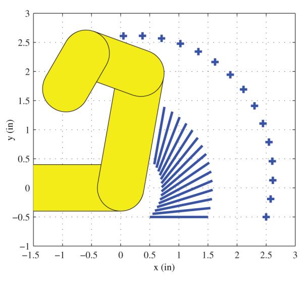
Desired motion for the finger
C. Mechanism Selection
In a typical mechanism design problem, the desired output is the position and orientation of a single end-effector which is attached to a designated output link. The designer may choose to design for a specific number of configurations, which produce a system of equal number of equations and unknowns. Alternatively, an excess of configurations may be used, such as those generated from a desired trajectory. In this case the design problem is to optimize the mechanism to most closely reach all of the trajectory configurations, using a squared error or some other measure of accuracy. This approach was used successfully in [14]. In the present application, however, the desired output of the mechanism design is two end-effectors; one controlling the position and orientation of the proximal phalanx and a second controlling the position of the middle phalanx. To achieve this goal, two output links are required.
There are numerous possibilities of planar topologies that may be designed with two output links. As a starting point, six-bar mechanisms with revolute joints were considered. Configurations of six-bar chains are presented in [15]. After numerous attempts at synthesizing Watt type six-bar chains, it was determined that the planar six-bar does not have the necessary solution span to produce the desired motions. This led to the consideration of eight-bar mechanisms, which proved successful. The solution presented here is an eight-bar planar mechanism with all revolute joints (Chain 1 from [16]). A diagram of the mechanism is given in Figure 2 above. The output is the position (P) and angle (μp) of the proximal phalanx and the position (M) of the middle phalanx. The mechanism consists of 10 revolute joints (G, G1, which are fixed, and W, W1, W2, H, H2, Y, Y1, and Y2), seven configuration angles (θ, θ1, ϕ, ϕ1, ϕ2, ψ, and ψ1), seven structural angles (α, α2, δ, δ2, γ, γ2, and μ), and 13 structural lengths (d1 to d11, m, and m2).
Fig. 2.
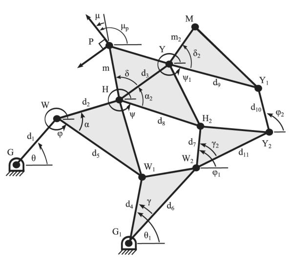
Eight-bar mechanism diagram for the finger curling mechanism
D. Eight-bar Mechanism Design Equations
The eight-bar mechanism chosen for the finger-curling mechanism consists of 3 four-bar mechanisms connected in series, with output configuration P and μp attached to the middle four-bar loop and the output point M attached to the outer four-bar loop, as shown in Figure 2. The design equations for this mechanism include 3 separate paths to each output position (P and M). For the proximal phalanx the simplest path follows the joint chain GWHP . This vector equation has the detailed form
| (1) |
where c and s stand for cosine and sine, respectively.
The other two path equations for the proximal phalanx are the joint chains G1W1WHP and G1W2H2HP. These equations are similar to Equation 1 above. In a similar fashion, three path equations for the middle phalanx position are defined by the joint chains GWHYM, G1W2H2HYM, and G1W2Y2Y1YM. In addition to the above output path equations described above, three loop constraint equations must be satisfied. The inner loop constraint equation has the form
| (2) |
The other two loop equations can be defined in a similar fashion. The loop constraint equations for both the middle and outer loops can be defined by the joint chains GWHH2W2G1G = 0 and GWHYY1Y2W2G1G = 0.
The output angle μp is related to the configuration angle ψ and structural angles α2, δ, and μ with the equation ψ = μp – α2 – δ – μ. This equation can be substituted into the path equations and loop equations previously presented.
The result is a system of 18 equations in 6 configurations angles (θ, θ1, ϕ, ϕ1, ϕ2, and ψ1), seven structural angles (α, α2, δ, δ2, γ, γ2, and μ), 13 link lengths (d1 to d11, m, and m2), and two base positions (Gx, Gy, G1x, and G1y). Because only one of the configuration angles is independent (in this application, we have chosen θ), the 18 design equations have 25 unknowns for each desired configuration of the outputs (position and angle of the proximal phalanx and position of the middle phalanx). For a direct solution, this requires 8 desired configurations. For our application, however, we have chosen to specify a series of configurations along the desired curling motion exceeding the minimum eight, so that the design problem becomes an optimization problem; determine the structure variables and a set of n configuration angles (θ1 through θn) that most accurately reach the n desired configurations.
E. Optimization Constraints
There are numerous constraints that must be included in the optimization in order to achieve the desired results. Several constraints can be implemented with simple upper and lower bounds. For example, the location of the base points G and G1 were constrained within the following ranges: −8 < Gx < 6, −6 < Gy < −1.2, −8 < G1x < 6, −6 < G1y < −1.2. These limits on the location of the base points keeps them located off of the back of the hand and at a reasonable distance from the desired configuration points.
The structure lengths were also constrained with upper and lower bounds, .4 < d1 – d11, m, m2 < 4. The lower bound keeps the joints at a manufacturable distance and the upper bound keeps the link lengths small so that the synthesized mechanism is compact. Using the law of cosines, constraints were also applied to the remaining six distances between joints that are not directly controlled by the structural length variables, such as the distance between joints H and W1. The structural angles, however, were not constrained, as doing so unnecessarily limits the search space during optimization. These angles may be trimmed after optimization as needed.
It was also necessary to constrain the mechanism design so that the location of any two joints during the desired motion do not interfere. For example, depending on the structural variables, it may be possible for joints W1 and H2 to collide for some relative angle θ1 - ϕ1. To complete this set of constraints, the distances between all joints that might collide must be calculated at each configuration of the mechanism. These distances are constrained to be between 0.4 and 8 inches in order to keep the mechanism both manufacturable and compact.
A final set of constraints, while not simple to implement, are required to generate the desired mechanism. Specifically, it is necessary to constrain the location of the joints to behind the finger for all desired configurations. This cannot be achieved with upper and lower bounds, because the allowable position of the joints depends on the configuration of the desired finger configuration. To implement these constraints, three vectors are defined at each configuration of the finger, one starting at the base (vb), one at the desired proximal phalanx position (vp), and one at the desired middle phalanx position (vm). The vectors are perpendicular to the surface of the base, proximal phalanx, and middle phalanx for each angle, and pointing away from the hand, as shown in Figure 3. An additional set of three vectors (ub, up, um) are created for each arbitrary joint J. These vectors start at the same respective points as vb, vp, and vm, but they all point the to current location of the joint.
Fig. 3.
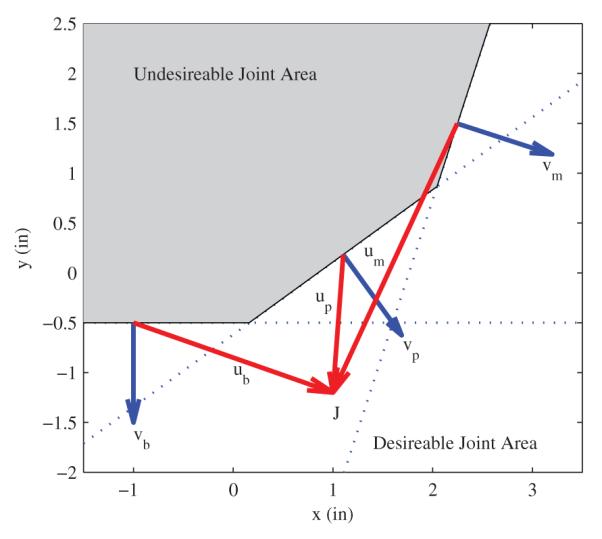
Vectors for constraining joint location for the 8-bar linkage
As it can be seen in Figure 3, the arbitrary joint located at J is safely clear of the undesirable joint area, as defined by the current location of finger. The maximum of the three dot products between the corresponding v and u vectors gives the distance of the joints away from the hand at the current configuration. As long as this value is positive, the joint position is safely located behind the hand. Therefore, the maximum of the three dot products is constrained at each configuration to be between 0.1 and 6 inches. This constraint keeps each joint location behind the hand during all desired output configurations.
III. Results
Using the design equations and the constraints described in the previous section, an eight-bar mechanism candidate suitable for our intended robotic device was achieved. The solution was found using a constrained nonlinear optimizer (fmincon function in Matlab). The optimization process included randomly generated initial conditions. A visual check was used to screen solutions from each attempt at optimization. Those with a promising structure were further optimized by both exploring initial conditions near the solution and by allowing more iterations and setting tighter stopping conditions for the optimization. The structural variables of the selected solution are given in Figure 4 below.
Fig. 4.
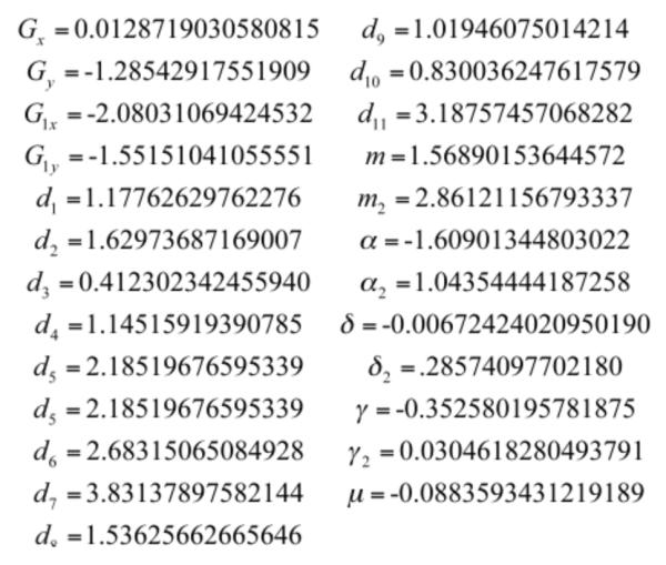
Resulting eight-bar linkage parameters
Figure 5 shows the selected solution and a few configurations during the curling motion.
Fig. 5.

Resulting eight-bar linkage
IV. Conclusions
The results presented for the finger mechanism are at the prototype stage. Although these initial results look promising, further work is necessary to determine the validity of the proposed mechanism.
The solution finger mechanism meets many of the criteria previously identified. It is confined to the back of the hand and it successfully produces the desired angles and positions of the proximal phalanx and the desired positions of the middle phalanx during the specified motion. There is, however, a tradeoff in terms of mechanism complexity. The proposed solution has seven links which will require complex shapes in order to clear each other. In addition, the mechanism has 11 revolute joints which must be implemented with both low friction and minimum backlash less the mechanism become unwieldy and unstable to control. We believe this can be achieved, in part, due to the stabilizing nature of the inherent parallel linkages in the designed mechanism. This does, however, require precise machining to ensure parallelism between all rotation axes.
The next step for the mechanism optimization is to identify a small subset of structural variables, that when modified in a known fashion, will produce a mechanism which tracks a different desired set of trajectories. It will be important to choose the variable subset as to avoid the dissassembly of the mechanism joints. In a fashion similar to [14], this will allow the mechanism to be re-configured to varying finger sizes without rebuilding the entire mechanism.
Acknowledgment
The project described is supported by Grant Number NIH-R01HD062744-01 from NCHHD. The content is solely the responsibility of the authors and does not necessarily represent the official views of the NCHHD or the National Institutes of Health.
Contributor Information
Eric T. Wolbrecht, Dep. of Mechanical Engineering University of Idaho Moscow, Idaho, USA ewolbrec@uidaho.edu
David J. Reinkensmeyer, Deps. of Mechanical and Aerospace Eng., Anatomy and Neurobiology, and Biomedical Engineering University of California, Irvine Irvine, CA, USA dreinken@uci.edu
Alba Perez-Gracia, Institut de Robòtica i Informàtica Industrial (CSIC-UPC) Barcelona, Spain; and: School of Engineering, Idaho State University Pocatello, Idaho, USA aperez@iri.upc.edu.
References
- [1].Frick EM, Alberts JL. Combined use of repetitive task practice and an assistive robotic device in a patient with subacute stroke. Physical Therapy. 2006;vol. 86(10):1378–1386. doi: 10.2522/ptj.20050149. [DOI] [PubMed] [Google Scholar]
- [2].Reinkensmeyer DJ, Galvez JA, Marchal L, Wolbrecht ET, Bobrow JE. Some key problems for robot-assisted movement therapy research: A perspective from the university of california at irvine. Proc. 10th IEEE Intl. Conf. on Rehabilitation Robotics; Noordwijk, The Netherlands: ASME, Ed.; 2007. pp. 1009–1015. [Google Scholar]
- [3].Reinkensmeyer L. M. Crespo and D. J. Review of control strategies for robotic movement training after neurologic injury. J Neur Eng Reh. 2008 doi: 10.1186/1743-0003-6-20. vol. submitted. [DOI] [PMC free article] [PubMed] [Google Scholar]
- [4].Brewer BR, McDowell SK, Worthen-Chaudhari LC. Post-stroke upper extremity rehabilitation: a review of robotic systems and clinical results. Top. Stroke Rehabil. 2007;vol. 14:22–44. doi: 10.1310/tsr1406-22. [DOI] [PubMed] [Google Scholar]
- [5].Krebs HI, Mernoff S, Fasoli SE, Hughes R, Stein J, Hogan N. A comparison of functional and impairment-based robotic training in severe to moderate chronic stroke: a pilot study. NeuroRehabilitation. 2008;vol. 23:81–87. [PMC free article] [PubMed] [Google Scholar]
- [6].Mehrholz J, Platz T, Kugler J, Pohl M. Electromechanical and robot-assisted arm training for improving arm function and activities of daily living after stroke. Cochrane Database Syst. Rev. 2008;vol. 4:CD006876. doi: 10.1002/14651858.CD006876.pub2. [DOI] [PubMed] [Google Scholar]
- [7].Wolbrecht ET, Reinkensmeyer DJ, Bobrow JE. Optimizing compliant, model-based robotic assistance to promote neurorehabilitation. IEEE Transactions Neural Systems and Rehabiltation Engineering. 2008;vol. 16:286–297. doi: 10.1109/TNSRE.2008.918389. [DOI] [PubMed] [Google Scholar]
- [8].Hesse S, Werner C, Pohl M, Rueckriem S, Mehrholz J, Lingnau M. Computerized arm training improves the motor control of the severely affected arm after stroke: a single-blinded randomized trial in two centers. Stroke. 2005;vol. 36:1960–1966. doi: 10.1161/01.STR.0000177865.37334.ce. [DOI] [PubMed] [Google Scholar]
- [9].Takahashi C, Der-Yeghiaian L, Le V, Motiwala R, Cramer S. Robot-based hand motor therapy after stroke. Brain : a journal of neurology. 2008;vol. 131:425–437. doi: 10.1093/brain/awm311. [DOI] [PubMed] [Google Scholar]
- [10].Itoa S, Kawasakia H, Ishigureb Y, Natsumec M, Mouria T, Nishimotod Y. A design of fine motion assist equipment for disabled hand in robotic rehabilitation system. J. Franklin Inst. 2009 vol. doi:10.1016/j.jfranklin.2009.02.009. [Google Scholar]
- [11].Worsnopp T, Peshkin M, Colgate J, Kamper D. An actuated finger exoskeleton for hand rehabilitation following stroke. Proc. 10th IEEE Intl. Conf. on Rehabilitation Robotics, Noordwijk, The Netherlands. 2007:896–901. [Google Scholar]
- [12].Thaut M. The future of music in therapy and medicine. Ann N Y Acad Sci. 2005;vol. 1060:303–308. doi: 10.1196/annals.1360.023. [DOI] [PubMed] [Google Scholar]
- [13].Friedman N, Chan V, Bachman M, Reinkensmeyer DJ. Musicglove: An analytic tool and music based device for motivating and quantifying hand movement rehabilitation by using functional grips to play music hand rehabilitation. submitted to 33rd Int. Conf. of the IEEE Engineering in Medicine and Biology Society (EMBC 11); Boston, MA. August 30 - September 3, 2011; [DOI] [PubMed] [Google Scholar]
- [14].Sands D, Perez-Gracia A, McCormack J, Wolbrecht E. Design method for a reconfigurable mechanisms for finger rehabilitation. Proceedings of the 2010 IASTED Robotics and ApplicationsConference; Cambridge, Massachusetts, USA. November 1 3, 2010.2010. [Google Scholar]
- [15].McCarthy G. Soh and J. The synthesis of six-bar linkages as constrained planar 3r chains. Mechanism and Machine Theory. 2008;vol. 43:160170. [Google Scholar]
- [16].Soh J. M. McCarthy and G. Geometric Design of Linkages. 2nd ed Springer-Verlag; New York: 2010. [Google Scholar]