

Abstract
Microfluidic synthesis of nanoparticles (NPs) can enhance the controllability and reproducibility in physicochemical properties of NPs compared to bulk synthesis methods. However, applications of microfluidic synthesis are typically limited to in vitro studies due to low production rates. Herein, we report the parallelization of NP synthesis by 3D hydrodynamic flow focusing (HFF) using a multilayer microfluidic system to enhance the production rate without losing the advantages of reproducibility, controllability, and robustness. Using parallel 3D HFF, polymeric poly(lactide-co-glycolide)-b-polyethyleneglycol (PLGA-PEG) NPs with sizes tunable in the range of 13–150 nm could be synthesized reproducibly with high production rate. As a proof of concept, we used this system to perform in vivo pharmacokinetic and biodistribution study of small (20 nm diameter) PLGA-PEG NPs that are otherwise difficult to synthesize. Microfluidic parallelization thus enables synthesis of NPs with tunable properties with production rates suitable for both in vitro and in vivo studies.
Keywords: Nanoparticles, Nanoprecipitation, 3D flow focusing, Microfluidics, Block copolymers
Introduction
Polymeric nanoparticles (NPs) have shown great promise as nanocarriers for drug delivery.1–3 NPs made of poly(lactide-co-glycolide)-b-polyethyleneglycol (PLGA-PEG) block copolymers are particularly appealing as nanomedicines because they are biodegradable and biocompatible, have the ability to incorporate chemical moieties including drug molecules and targeting agents, and can controllably release their payload.4–6 Indeed, targeted PLGA-PEG NPs for prostate cancer therapy have successfully completed Phase I clinical trials and are poised to impact human health.7
However, the translation of NPs to the clinic faces several challenges, with the majority of the NPs not making it beyond the proof-of-concept stage.8,9 Major issues include the extensive in vitro and in vivo screening and optimization required, and the batch-to-batch variability in manufacture of NPs. While polymeric NPs are typically synthesized in bulk by the nanoprecitipation/solvent exchange method or by emulsification using surfactants, microfluidic platforms offer reaction environments that are precisely controlled at the microscale. As a result, microfluidic platforms have been recently adopted for the synthesis of NPs in a more controllable and reproducible manner.9–12 Microfluidic platforms also allow systematic tuning of the biophysicochemical properties of NPs, facilitating their screening and optimization.8,9,13–16 We have demonstrated the controlled synthesis of PLGA-PEG NPs by rapid and tunable mixing in microfluidic platforms known as 2D hydrodynamic flow focusing (HFF) and 3D HFF.13,17 3D HFF isolates the precipitating polymers from microchannel walls and eliminates microchannel clogging, which has enabled reproducible synthesis of monodisperse NPs with tunable sizes from 30–230 nm. Synthesis of lipid NPs using rapid mixing in microfluidic channels by microvortices and herringbone microstructures has also been reported.18–20
Despite these advances, the role of microfluidic platforms in the development of drug delivery systems faces some challenges. While in vitro studies require small amounts of NPs (e.g., ~50 μg/well), subsequent in vivo studies require significantly larger amounts (e.g., ~5 mg/mouse). Mixers that are suitable for larger-scale synthesis18,21 are not well-suited for creating a library of NPs for in vitro screening. In devices such as 3D HFF that are well-suited for in vitro screening of NPs, modifying the experimental procedures to increase the yield drastically affects the physicochemical properties of NPs. For example, changing the platform’s architecture to tolerate higher internal pressure affects the mixing time and the physicochemical properties of the NPs. Therefore, parallelization of the microchannels is a promising way to meet the NP production yields required for in vivo studies; such parallel process approaches have been studied for emulsion droplet generation22–27 and in the chemical engineering industry.28
Herein, we report parallel synthesis of NPs using a multilayer microfluidic system to enhance the production yield without losing the advantages of reproducibility, controllability, and robustness of 3D HFF. The relevance of this novel microfluidic design for the development of PLGA-PEG NPs was assessed by synthesizing NPs in the range of 13–150 nm with high production rates. We show that NPs produced at high production rates have identical properties as those prepared with single stream channels. Finally, as a proof of concept, we performed in vivo pharmacokinetic (PK) and biodistribution study using PLGA-PEG NPs rapidly synthesized by the parallel 3D HFF. This parallel microfluidic system extends the range of applications of HFF for controlled synthesis of NPs with tunable properties from in vitro to in vivo studies.
Methods
Fabrication of multilayer poly(dimethylsiloxane) (PDMS) microfluidic device
Multilayer 3D HFF microfluidic device was prepared using multilayer photolithography and multilayer soft lithography. Master molds for the bottom and upper layers were patterned in SU-8 photoresist (SU-8 2100, MicroChem Corp., Newton, MA, USA) via conventional photolithography. Post arrays for interconnecting holes were patterned in SU-8 on top of the bottom layer with precise alignment using an UV aligner (MA-4, Karl Suss, Garching, Germany). A thin PDMS (4:1 base to hardener mixture, Dow Corning, Midland, MI, USA) membrane was spin-coated on the master mold for bottom layer with post arrays. The spin speed (600 rpm for 30 s) was chosen to precisely control the membrane thickness to be slightly lower than the interconnect post height. The upper PDMS microchannel was prepared using conventional replica molding of PDMS (20:1 base to hardener mixture) from the SU-8 master for upper layer. The upper PDMS channel was aligned under a microscope and bonded on top of bottom PDMS membrane using oxygen plasma treatment (PDC-001, Harrick Plasma, Ithaca, NY, USA) and then peeled off along with the bottom layer. To assemble the final device, the multilayer PDMS channel was bonded with a slide glass via oxygen plasma and connected to tubing.
Preparation of PLGA-PEG NPs
PLGA10K-PEG5K, PLGA27K-PEG5K, PLGA45K-PEG5K, and PLGA95K-PEG5K (Boehringer Ingelheim GmbH, Ingelheim, Germany and Akina Inc., West Lafayette, IN, USA) was dissolved in acetonitrile (ACN, Sigma-Aldrich, St. Louis, MO, USA) at concentrations of 10–50 mg/mL. ACN and deionized water were employed as vertical and lateral sheath streams, respectively. While NPs can be prepared using different organic solvents, ACN was chosen because it is compatible with PDMS.29 The PLGA-PEG precursor in ACN was introduced to the microchannel connected with the middle interconnecting holes. Pure ACN was introduced to the microchannel connected with the first and the third interconnecting holes. During the NPs synthesis, the flow rates were controlled by syringe pumps (Harvard Apparatus, Holliston, MA, USA) and the device was observed using an inverted microscope (Eclipse TS 100, Nikon, Tokyo, Japan). To confirm the vertical focusing, laser scanning confocal microspcope (LSM 510, Carl Zeiss Microscopy, Göttingen, Germany) was used. To obtain the confocal microscope images, aqueous solution of rhodamine 6G (Rh6G, Sigma-Aldrich, St. Louis, MO, USA) and fluorescein isothiocyanate (FITC, Sigma-Aldrich, St. Louis, MO, USA) were used as core and vertical sheath fluids, respectively. In case of the bulk synthesis, 100 μL of polymeric precursor solution was mixed drop-wise with 1 mL of water for about 2 h under magnetic stirring. The resulting NP suspensions were purified by ultrafiltration using Amicon Ultracel 100 K membrane filters (EMD Millipore, Billerica, MA, USA), washed three times with water, and resuspended in water or PBS.
Characterization of PLGA-PEG NPs
The size distribution by volume fraction of PLGA-PEG NPs was measured using dynamic light scattering with Zetasizer Nano ZS (Malvern Instruments Ltd., Malvern, Worcs, UK). The synthesized PLGA-PEG NPs were imaged by TEM (200CX, JEOL, Tokyo, Japan) with negative staining by uranyl acetate (Electron Microscopy Sciences, Hatfield, PA, USA). For the release study, we dialyzed docetaxel-loaded NPs in 20 L of PBS, pH 7.4, at 37 °C using a 10 kDa cutoff membrane (Slide-A-Lyzer MINI Dialysis Devices, Thermo Scientific, Rockford, IL, USA). The amount of docetaxel released from the NPs was measured by HPLC (1100 Series, Agilent Technologies, Santa Clara, CA, USA).
In vivo pharmacokinetics (PK) and biodistribution
All experiments were conducted as approved by the MIT Committee on Animal Care (protocol #0710-055-13) and are in compliance with institutional and NIH guidelines. The procedures for the in vivo PK experiments were adapted from a method reported elsewhere.30–32 For the in vivo experiments, 5 wt% Alexa-fluor 647 (Life Technologies, Grand Island, NY, USA) conjugated to PLGA45K (PLGA45K-A647) using 1-ethyl-3-(3-dimethylaminopropyl)-carbo-diimide/N-hydroxysuccinimide chemistry was added to the polymeric precursor. Male and female Balb/c mice weighting 25 g were intravenously dosed with 5 mg of Alexa-fluor 647-labeled NPs via subclavian vein injection. At different time intervals (5, 15, 30 min, and 1, 2, 4, 6 h) 50 μL of blood was sampled from the saphenous vein using a heparinized hematocrit capillary tube. To minimize the amount of blood removed on each animal, the different time-points were spread-out throughout the group to ascertain that each mouse was not sampled more than 5 times. Twelve hours after injection, a last blood sample was collected by cardiac puncture and the animals were euthanized by cardiac perfusion of PBS under deep anesthesia. Tissues (heart, lung, liver, spleen, and kidneys) were harvested for terminal biodistribution analysis (t = 12 h). Five animals were used in each group.
All samples were maintained on ice until analyzed for fluorescent quantification of NPs in plasma and organs (within 4 h). Blood samples were centrifuged at 2,000 rcf for 10 min, at 4 °C. The isolated plasma was collected and the volume was completed to 50 μL with mouse plasma (Equitech-Bio, Kerrville, TX, USA). The fluorescence intensity was measured (λex: 650 nm, λem: 665 nm) on a 96-well plate-reader (Tecan, Männedorf, Switzerland) and quantified using an 8-point calibration curve obtained from serial dilution in plasma of each formulation. The limit of quantification (LOQ) was determined as the lowest concentration for which the coefficient of variation in the calibration curve was below 10 % (19 μg/mL). Samples with fluorescence below the LOQ were omitted. Moreover, to minimize the impact of fluorescence quenching in concentrated samples, samples with concentrations above 1,250 μg/mL were further diluted until linearity in signal was achieved. The total concentration in plasma at each time-point was obtained by multiplying the concentration of each sample by the dilution factor used for preparation. The biodistribution data were obtained from imaging the organs on an IVIS molecular imaging system (λex: 660 nm, λem: 680 nm). To account for the variability in the fluorescence of each formulation, the Total Radiant Efficiency was normalized by the slope of each calibration curve.
PK data were treated by non-compartmental analysis of plasma concentration vs. time profiles. Cmax corresponds to the maximum concentration measured while C0 is extrapolated as the Y intercept of linear least-squares regression on the semilog plot of the plasma concentration vs. time curve. Vd extrap is determined by dividing the injected dose by C0. The apparent first-order terminal elimination rate (Kel) was estimated by linear least-squares regression on the semilog plot of the plasma concentration vs. time curve. t1/2 is equal to ln2/Kel. AUC0-t was calculated by the trapezoidal method from 0 to the last quantifiable time-point. Areas under the blood concentration-time curve from time zero to infinity (AUC0-inf) were calculated by adding AUC0-12 h to the ratio of the last measurable concentration to Kel. Total Clearance was quantified as the injected dose divided by AUC0-inf.
Statistics were computed with SigmaPlot 11.0 software (Systat Software, Inc., San Jose, CA, USA). Differences in group means were calculated by standard unpaired t test or Mann–Whitney U test. The non-parametric tests were used if samples failed tests for equality of variance and/or normality with the Kolmogorov-Smirnov test. A value of P < 0.05 was considered significant. Table 1 lists which tests were used in each figure and table.
Table 1.
The summary of calculated PK parameters, P values, and statistical test methods.
| 20 nm NPs | 35 nm NPs | P value | Statistical test | |
|---|---|---|---|---|
| Half-life (h) | 1.3 ± 0.19 | 1.7 ± 0.30 | p = 0.095 | Mann–Whitney |
| Ke (h−1) | 0.5 ± 0.09 | 0.4 ± 0.09 | p = 0.095 | Mann–Whitney |
| AUC0-12h (%ID.h.mL−1) | 168 ± 56 | 156 ± 61 | p = 0.371 | t-test |
| AUC0-inf (%ID.h.mL−1) | 169 ± 56 | 157 ± 62 | p = 0.378 | t-test |
| Vd extrap (mL) | 1.2 ± 0.50 | 2.0 ± 0.83 | p = 0.055 | t-test |
| Vd area (mL) | 1.3 ± 0.84 | 1.8 ± 0.74 | p = 0.186 | t-test |
| Clearance (mL/h) | 0.7 ± 0.37 | 0.7 ± 0.23 | p = 0.461 | t-test |
| Cmax (%ID.mL−1) | 81 ± 25 | 72 ± 27 | p = 0.301 | t-test |
Results
Design and fabrication of multilayer PDMS microfluidic device
The fabrication process for the parallel 3D HFF device is illustrated in Figure 1. The parallel 3D HFF devices were obtained by casting PDMS on a master mold fabricated in SU-8 photoresist using two-step lithography. The spin speed was tuned to precisely control the PDMS thickness to be slightly lower than the interconnecting post height. The channel width at the vertical focusing region and mixing region were 100 μm and 20 μm, respectively. The height of upper and lower microchannels was fixed at 100 μm.
Figure 1.

3D Schematic illustration of fabrication procedure for the multilayer 3D HFF device. For clarity, the single channel 3D HFF device is depicted.
Figure 2, A shows a photograph of the parallel 3D HFF device, with isolated upper (red) and lower (blue) layers filled with dye to highlight the geometries of the microchannels. Due to the two-layer design, the device is simplified and can be interfaced with only 3 inlets and 1 outlet tubing (Figure 2, A). 3D HFF was achieved by three sequential interconnecting holes for vertical focusing followed by a conventional cross junction for horizontal focusing.17 The organic phases (i.e., polymer solution in ACN and pure ACN) were supplied from upper to lower layers through the three sequential interconnecting holes, visualized in Figure 2, B using red and green food coloring dyes to represent the PLGA-PEG polymer in ACN solution and pure ACN, respectively. The pure ACN streams focus the polymer stream vertically to isolate it from the top and bottom walls to prevent channel fouling, while the water stream focuses the organic streams horizontally to precipitate the NPs.17 The device was designed with appropriate flow resistances to maintain an even distribution of flows to the parallel channels (Figure 2, A and C).
Figure 2.
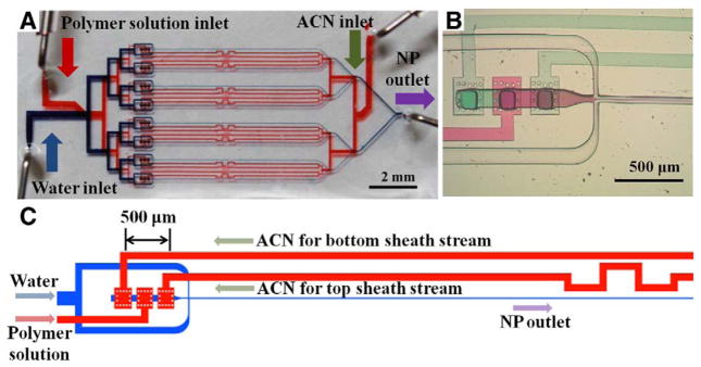
3D HFF microfluidic device for parallel NP synthesis. (A) Device visualized using red and blue food coloring dyes in the upper and lower microchannels, respectively. PDMS was spin-coated thicker than the SU-8 post arrays (i.e., interconnecting holes were closed) to isolate the channels. (B) Optical microscope image of the 3D HFF region. Here, red and green food coloring dyes represent the PLGA-PEG polymer in ACN solution and pure ACN, respectively. (C) Schematic illustration of one of the 8 parallel 3D HFF units in the device.
Simulation and experimental visualization of vertical focusing
The vertical focusing 3D HFF with three sequential inlets is strongly affected by the shapes of interconnecting holes. The effect of the geometry of the interconnecting holes on the vertical focusing was examined by using 3D finite element simulations using COMSOL (COMSOL Inc., Stockholm, Sweden) (Figure 3, A). Round interconnecting holes resulted in non-uniform distribution of concentration profiles. Likewise, rectangular interconnecting holes with lengths smaller than 100 μm resulted in arched vertical streams. The most uniform concentration profiles were achieved when rectangular interconnecting holes with lengths larger than 100 μm were used. Since larger SU-8 post arrays for replication of interconnecting holes may hinder the uniformity of thin PDMS layer during the spin coating process, the (streamwise) length of the interconnecting holes was fixed at 100 μm. To verify the effect of the interconnect hole geometry, the performance of the multilayer 3D HFF device was examined using confocal microscopy with aqueous Rh6G (red) and FITC (green) fluorescent dye solutions as the polymer in ACN and ACN streams, respectively. As predicted by the simulations, more uniform vertical focusing could be achieved using rectangular interconnecting holes (100 μm × 120 μm) compared to circular holes (Figure 3, B and C).17 The cross-section profiles and heights of the vertically focused streams obtained by confocal microscopy were also in good agreement with the 3D finite element simulations at various fractions of polymer flow in organic flow (f) (Figure 3, D and E).
Figure 3.

Vertical focusing in the 3D HFF device (Re = 0.833). Both width and height of the lower microchannel are 100 μm. (A) Perspective views of 3D finite element simulations at the vertical focusing region with round (120 μm in diameter), rectangular (50 μm × 120 μm), rectangular (100 μm × 120 μm), and square (120 μm × 120 μm) shapes of interconnecting holes. Here, the fraction of polymer flow in organic flow (f) is 0.3. (B) Cross-sectional side view and (C) cross-sectional front view of confocal microscopy images at the vertical focusing region when the fraction of polymer flow in organic flow (f) is 0.3. Width and length of interconnecting holes are 120 μm and 100 μm, respectively. Fluid flows in the x-direction after focusing. (D) Height of vertically focused polymeric stream as a function of f. (E) Cross-sectional side view from the 3D finite element simulation and confocal microscope images at the vertical focusing region as a function of f.
Preparation and characterization of PLGA-PEG NPs
PLGA-PEG NPs with a range of sizes from 13 nm to 150 nm were prepared using the parallel 3D HFF device, demonstrating its utility for the synthesis of NPs with precise control over the particle size. To accomplish this size control, we varied both the PLGA block lengths (10, 27, 45, and 95 kDa) and polymer concentration in ACN (10–50 mg/mL) (Figure 4, A). For some conditions 2D HFF and the bulk synthesis method yielded polydisperse particles due to the aggregation of the polymeric precursor, whereas 3D HFF provided more homogeneous NPs. Figure 4, B shows the size distributions by volume fraction of NPs synthesized from PLGA45K-PEG5K precursor at high concentrations (50 mg/mL) using the three different methods (i.e., 3D HFF, 2D HFF, and bulk synthesis method). Here, the f of 3D HFF and 2D HFF were 0.7 and 1, respectively. Next, we; compared NPs prepared using the 8 parallel stream 3D HFF device to a single stream 3D HFF device fabricated in a similar manner. We observed that the size of NPs prepared with the single and 8 parallel 3D HFF was essentially identical within standard error (Figure 4, C). The size of NPs can be controlled simply by changing the flow ratio of polymer stream to the total flow rate of water (R).13,33 When PLGA10K-PEG5K at high concentration (50 mg/mL) is used, the size drops from 26 nm to 13 nm as the R decreased from 0.2 to 0.02 (Figure 4, D). Similarly, NPs size decreased from 40 nm to 20 nm as the R decreased when PLGA27K-PEG5K at high concentration (50 mg/mL) is used (Figure 4, E). To further assess to potential of the platform for drug delivery purposes, we assembled drug-encapsulating NPs by bulk synthesis and parallel 3D HFF using PLGA10K-PEG5K as the polymeric precursor and docetaxel as a model therapeutic agent. In both cases, the NPs behaved similarly with 50 % of the drug release achieved after 5 h (Figure 4, F).
Figure 4.
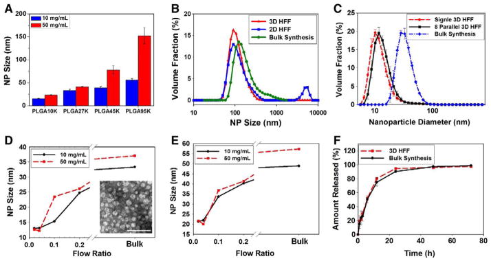
NP synthesis and drug release. (A) Effect of PLGA-PEG precursor concentrations on the size of synthesized PLGA-PEG NPs depending on the MW of polymeric precursors (f = 0.7, R = 0.1). (B) The size distribution by volume fraction of NPs prepared from PLGA45K-PEG5K by microfluidic 3D HFF at (f = 0.7, R = 0.1), 2D HFF (f = 1, R = 0.1), and bulk synthesis method. Here, the precursor concentration was 50 mg/mL. (C) The size distribution by volume fraction of NPs prepared from 10 mg/mL PLGA10K-PEG5K by single 3D HFF, 8 parallel 3D HFF, and bulk synthesis (f = 0.7, R = 0.04). (D, E) Effect of flow ratio on NPs size prepared from (D) PLGA10K-PEG5K and (E) PLGA27K-PEG5K by 3D HFF at f = 0.7. NPs prepared by 3D HFF were smaller in size than those obtained by bulk synthesis. The inset shows TEM image of the NPs prepared by 3D HFF (f = 0.7, R = 0.04). Scale bar is 100 nm. (F) Docetaxel release profile of NPs prepared from 50 mg/mL PLGA10K-PEG5K by 3D HFF and bulk synthesis.
Proof-of-concept in vivo PK and biodistribution of small NPs
As a proof of concept, we utilized the microfluidic platform to study the biological behavior of NPs with two different sizes prepared by controlling the mixing time. In vivo PK and bio-distribution were examined using Alexa-fluor 647 to label the NPs synthesized by the 8 parallel 3D HFF. Because Alexa-fluor 647 conjugated PLGA45K (PLGA45K-A647) was added to the PLGA10K-PEG5K precursor (5 wt%), the diameter of Alexa-fluor 647-labeled NPs was slightly increased compared to unlabelled NPs. At R = 0.04 and 0.2, the average diameters of Alexa-fluor 647-labeled NPs were 20 nm and 35 nm, respectively.
Interestingly, these NPs showed similar behavior when injected intravenously to mice without significant differences in circulation profiles and PK parameters (Figure 5, A and Table 1). Similarly, terminal distribution of the fluorescence in organs of the mononuclear phagocyte system (i.e., liver, spleen, and lungs)32 as well as the fluorescence in the kidneys and heart were comparable for both NPs (Figure 5, B).
Figure 5.

PK and biodistribution in mice of small NPs synthesized by 3D HFF. (A) The systemic circulation lifetime of Alexa-fluor 647-labeled PLGA10K-PEG5K NPs prepared with two different flow ratios to tune the size (R = 0.04 and 0.2 for 20 nm and 35 nm diameters, respectively). (B) The fluorescence intensity per organ of Alexa-fluor 647-labeled NPs at 12 h from intravenous injection. Five animals were used in each group. Both NPs showed similar behavior when injected intravenously to mice without significant differences in circulation profiles, PK parameters, and terminal distribution of the fluorescence in organs.
Discussion
We demonstrated the parallelization of microchannels to increase production yield without impairing reproducibility, controllability, and robustness of microfluidic synthesis of NPs. In principle, the parallelization strategy could expand to clinically relevant production rates.9 Recently, fabrication of parallelized PDMS microfluidic devices was demonstrated,23,24,26 but manual drilling or punching that provide limited accuracy and repeatability between devices were used to fabricate the interconnecting holes. In 3D HFF with three sequential inlets, the lateral position of the inlet holes significantly affects the vertical focusing, which is difficult to control by manual drilling.17 Instead, we defined the interconnecting holes in the parallel 3D HFF device by patterned SU-8 posts, which allowed for optimization of their cross-sectional geometry and excellent alignment with the microchannels. This approach reduced the manual interventions during the manufacturing process and resulted in lower variability of the chip-to-chip performance.34
The flow conditions of each 3D HFF unit in the 8 parallel 3D HFF device are designed to be the same as those in a single 3D HFF channel device. Therefore, the size of NPs prepared with the single and 8 parallel 3D HFF was essentially identical within standard error (Figure 4, C). In contrast, we observed a large difference between the 3D HFF and bulk synthesis (Figure 4, C). To achieve the same flow conditions in each 3D HFF unit in the 8 parallel 3D HFF device, the flow resistance in each channel should be precisely regulated. Since the flow resistance for laminar flow through a channel is proportional to the length of channel, the microchannels were branched symmetrically to balance the flow resistances. In addition, the microchannel for the top sheath stream was meandered to balance the flow resistances (Figure 2, C). The upper and lower layers are separated by a PDMS membrane, but the pressure in the lower layer is much larger than that of upper layer. As a result, the PDMS membrane protrudes into the upper microchannels where the upper and lower microchannels cross, increasing the resistance of upper microchannel. The resistance increase is higher when the area of channel overlap region is larger. Since PDMS made of 4:1 base to hardener mixture is stiffer, 4:1 base to hardener mixture was used to minimize the protrusion of the PDMS membrane. In addition, the microchannels were branched off at the overlapping region to distribute the effect of resistance increase evenly. Since the parallel channels are coupled to each other, dust or aggregates of PLGA-PEG impede an even distribution of flow to the parallel channels. Square PDMS posts, which could filter out the dusts and aggregates, were therefore placed around the interconnecting holes (Figure 2, B and C).
Parallel 3D HFF devices were obtained by casting PDMS on a master mold fabricated in SU-8 photoresist using two-step lithography. Since the interconnecting holes between upper and lower PDMS channels were defined by patterned SU-8 posts, their shape could be optimized and excellent alignment of the holes and channels could be achieved. Because of the optimal shape and excellent alignment of interconnecting holes, the vertically focused stream did not touch the PDMS microchannels even at high f (f = 0.7). Therefore, NPs with uniform size distribution could be synthesized consistently in case of 3D HFF. However, 2D HFF and the bulk synthesis method yielded poly-disperse particles due to the aggregation of polymeric precursors in some cases.
Considering that the pure ACN sheath flows do not contain any NP precursors, this configuration allows us to maintain the yield of NPs while enabling robust operation of the system (Table 2). Minimal dilution of the precursor solution by pure ACN allowed the production rate of NPs to increase to 84 mg/h when 8 parallel 3D HFF was operated at high f (f = 0.7). This increase in yield shortens the preparation time for batches of NPs suitable for a series of in vivo mice experiments (25 mg) from over 5 h17 to less than 20 minutes, which is critical to minimize drug release during NP synthesis. Furthermore, the NP production rate could be increased further by increasing the flow ratio as well as by increasing the number of parallel microchannels.
Table 2.
The production rate of NPs and time required for synthesis of 25 mg of NPs for single flow focusing and 8 parallel flow focusing, respectively. Here, the flow ratio were fixed at R = 0.1.
| Single 3D HFF (f = 0.3)17 | Single 3D HFF (f = 0.7) | 8 3D HFF (f = 0.7) | |
|---|---|---|---|
| Flow rate of polymeric precursor | 1.5 μL/min | 3.5 μL/min | 28 μL/min |
| Flow rate of water | 50 μL/min | 50 μL/min | 400 μL/min |
| Polymer concentration | 50 mg/mL | 50 mg/mL | 50 mg/mL |
| Production rate | 4.5 mg/h | 10.5 mg/h | 84 mg/h |
| Time for 25 mg NPs | 334 min | 143 min | 18 min |
Many different organic solvents including tetrahydrofuran, acetone, and dimethylformamide have been used for conventional bulk NP preparation.5 However, PDMS tends to swell in presence of many organic solvents, which would alter the fluid dynamics in the PDMS device. We used ACN and water for NP preparation because they are compatible with PDMS.29 Other organic solvents including nitromethane, dimethyl sulfoxide, ethylene glycol, perfluorotributylamine, perfluorodecalin, and propylene carbonate can potentially be adopted for NP synthesis using our system as they do not swell PDMS.29
Since the size of NPs is one of the key factors that determine the biodistribution and therapeutic efficacy,3,8,32,35 the ability to tune NPs size is important. We further established the potential of this platform by reproducibly synthesizing NPs with sizes tunable between 13 and 150 nm. Self-assembly of NPs under conditions of the most rapid mixing with lowest MW PLGA block (10 kDa) resulted in the smallest NPs (~13 nm diameter), which is very difficult to achieve with bulk synthesis methods. Similarly the highest MW PLGA block (95 kDa) and high polymer concentration resulted in the largest NP sizes (~150 nm diameter). Interestingly, all NPs had consistent average size batch-to-batch, and uniform size distribution.
In HFF devices, for fixed MW and concentration of polymeric precursor, the size of the NPs strongly depends on the mixing time (τmix), which can be estimated by equation (1).13,33
| (1) |
Where D is diffusivity of the solvent, wf is width of the focused stream, w is channel width, and R is the ratio of flow rate of the organic stream to the total flow rate of water. NPs obtained using the microfluidic channels are smaller than those synthesized from the bulk synthesis method because the τmix is smaller than the characteristic aggregation time scale (τagg) (Figure 4, D and E).13 In the current devices, Eq. (1) predicts τmix in the range of 0.017–1.2 ms for typical flow ratios (R = 0.02–0.2). The influence of τmix on the size of NPs disappears when τmix is smaller than 0.066 ms (R = 0.04), suggesting that these NPs have reached the size limit for this specific copolymer.33
The ability to reproducibly synthesize small and monodisperse NPs exhibiting similar fate in vivo is particularly appealing in light of the recent literature reporting enhanced penetration of smaller NPs into solid tumors.36,37 If NPs of two different sizes exhibit similar PK, we may expect the smaller NPs to be more effectively penetrate into solid tumors. Microfluidic platforms are advantageous for synthesis of small NPs by nanoprecipitation due to their ability to rapidly mix the precursors; NPs prepared by bulk nanoprecipitation tend to be larger.13,17,33 A recent paper reported a different parallel flow focusing system that resulted in smaller NPs, although in vivo studies were not performed and the NP size was 50 – 200 nm.38
While is relatively simple to synthesize sub-30 nm inorganic NPs at large scales, it has remained challenging to synthesize polymeric NPs in this size range, especially loaded with drug and with controlled release properties. The parallel 3D HFF device enables the synthesis of small NPs with high production rates that allowed for in vivo studies. Since smaller NPs can penetrate more deeply into solid tumors,36,37 parallel microfluidic synthesis has the potential to lead to the development of improved NPs with better drug delivery performance compared to larger NPs obtained by bulk synthesis. Therefore, the use of the parallel 3D HFF device to synthesize a variety of such NPs would likely prove a very valuable tool in the pre-clinical in vivo screening of these materials for cancer therapy.
Acknowledgments
This research was supported by the Koch-Prostate Cancer Foundation Award in Nanotherapeutics (R.L. and O.C.F.), by the Concept Development Grant 5P50CA090381–09 from the Dana Farber Cancer Institute Prostate SPORE (O.C.F.), by NIH Grants EB015419 (O.C.F. and R.K.), CA119349 (R.L. and O.C.F.), and EB003647 (O.C.F.), by the National Cancer Institute Center of Cancer Nanotechnology Excellence at MIT-Harvard (U54-CA151884, R.L. and O.C.F.), and by the National Research Foundation of Korea (NRF) (No. 2012-K1A1A2048701, S.J. and O.C.F.). N.B. is supported by a Canadian Institute of Health Research (CIHR) post-doctoral grant. P.M.V. is supported by NSF Graduate Research Fellowship.
We thank Dr. Eric M. Pridgen for scientific discussion and insightful comments.
Footnotes
Conflict of Interest Statements: In compliance with the Brigham and Women’s Hospital and Harvard Medical School institutional guidelines, O.C.F. discloses his financial interest in BIND Biosciences, Selecta Biosciences, and Blend Therapeutics, three biotechnology companies developing nanoparticle technologies for medical applications. BIND, Selecta, and Blend did not support the aforementioned research, and currently these companies have no rights to any technology or intellectual property developed as part of this research. In compliance with MIT institutional guidelines, R.L. discloses his financial interest in BIND Biosciences, Selecta Biosciences, Blend Therapeutics, and Kala, four biotechnology companies developing nanoparticle technologies for medical applications. BIND, Selecta, Blend, and Kala did not support the aforementioned research, and currently these companies have no rights to any technology or intellectual property developed as part of this research.
References
- 1.Langer R. Drug delivery and targeting. Nature. 1998;392:5–10. [PubMed] [Google Scholar]
- 2.Farokhzad OC, Cheng J, Teply BA, Sherifi I, Jon S, Kantoff PW, et al. Targeted nanoparticle-aptamer bioconjugates for cancer chemotherapy in vivo. Proc Natl Acad Sci USA. 2006;103(16):6315–20. doi: 10.1073/pnas.0601755103. [DOI] [PMC free article] [PubMed] [Google Scholar]
- 3.Barreto JA, O’Malley W, Kubeil M, Graham B, Stephan H, Spiccia L. Nanomaterials: applications in cancer imaging and therapy. Adv Mater. 2011;23(12):H18–40. doi: 10.1002/adma.201100140. [DOI] [PubMed] [Google Scholar]
- 4.Farokhzad OC, Jon S, Khademhosseini A, Tran T-NT, LaVan DA, Langer R. Nanoparticle-aptamer bioconjugates: a new approach for targeting prostate cancer cells. Cancer Res. 2004;64(21):7668–72. doi: 10.1158/0008-5472.CAN-04-2550. [DOI] [PubMed] [Google Scholar]
- 5.Cheng J, Teply BA, Sherifi I, Sung J, Luther G, Gu FX, et al. Formulation of functionalized PLGA-PEG nanoparticles for in vivo targeted drug delivery. Biomaterials. 2007;28(5):869–76. doi: 10.1016/j.biomaterials.2006.09.047. [DOI] [PMC free article] [PubMed] [Google Scholar]
- 6.Farokhzad OC, Langer R. Impact of nanotechnology on drug delivery. ACS Nano. 2009;3(1):16–20. doi: 10.1021/nn900002m. [DOI] [PubMed] [Google Scholar]
- 7.Hrkach J, Von Hoff D, Ali MM, Andrianova E, Auer J, Campbell T, et al. Preclinical development and clinical translation of a PSMA-targeted docetaxel nanoparticle with a differentiated pharmacological profile. Sci Transl Med. 2012;4(128):128ra39. doi: 10.1126/scitranslmed.3003651. [DOI] [PubMed] [Google Scholar]
- 8.Kamaly N, Xiao Z, Valencia PM, Radovic-Moreno AF, Farokhzad OC. Targeted polymeric therapeutic nanoparticles: design, development and clinical translation. Chem Soc Rev. 2012;41(7):2971–3010. doi: 10.1039/c2cs15344k. [DOI] [PMC free article] [PubMed] [Google Scholar]
- 9.Valencia PM, Farokhzad OC, Karnik R, Langer R. Microfluidic technologies for accelerating the clinical translation of nanoparticles. Nat Nanotechnol. 2012;7(10):623–9. doi: 10.1038/nnano.2012.168. [DOI] [PMC free article] [PubMed] [Google Scholar]
- 10.Jahn A, Reiner JE, Vreeland WN, DeVoe DL, Locascio LE, Gaitan M. Preparation of nanoparticles by continuous-flow microfluidics. J Nanopart Res. 2008;10(6):925–34. [Google Scholar]
- 11.Marre S, Jensen KF. Synthesis of micro and nanostructures in microfluidic systems. Chem Soc Rev. 2010;39(3):1183–202. doi: 10.1039/b821324k. [DOI] [PubMed] [Google Scholar]
- 12.Yeo LY, Chang HC, Chan PPY, Friend JR. Microfluidic devices for bioapplications. Small. 2011;7(1):12–48. doi: 10.1002/smll.201000946. [DOI] [PubMed] [Google Scholar]
- 13.Karnik R, Gu F, Basto P, Cannizzaro C, Dean L, Kyei-Manu W, et al. Microfluidic platform for controlled synthesis of polymeric nanoparticles. Nano Lett. 2008;8(9):2906–12. doi: 10.1021/nl801736q. [DOI] [PubMed] [Google Scholar]
- 14.Valencia PM, Basto PA, Zhang LF, Rhee M, Langer R, Farokhzad OC, et al. Single-step assembly of homogenous lipid-polymeric and lipid-quantum dot nanoparticles enabled by microfluidic rapid mixing. ACS Nano. 2010;4(3):1671–9. doi: 10.1021/nn901433u. [DOI] [PMC free article] [PubMed] [Google Scholar]
- 15.Kolishetti N, Dhar S, Valencia PM, Lin LQ, Karnik R, Lippard SJ, et al. Engineering of self-assembled nanoparticle platform for precisely controlled combination drug therapy. Proc Natl Acad Sci USA. 2010;107(42):17939–44. doi: 10.1073/pnas.1011368107. [DOI] [PMC free article] [PubMed] [Google Scholar]
- 16.Valencia PM, Pridgen EM, Perea B, Gadde S, Sweeney C, Kantoff PW, et al. Synergistic cytotoxicity of irinotecan and cisplatin in dual-drug targeted polymeric nanoparticles. Nanomedicine. 2013;8(5):687–98. doi: 10.2217/nnm.12.134. [DOI] [PMC free article] [PubMed] [Google Scholar]
- 17.Rhee M, Valencia PM, Rodriguez MI, Langer R, Farokhzad OC, Karnik R. Synthesis of size-tunable polymeric nanoparticles enabled by 3D hydrodynamic flow focusing in single-layer microchannels. Adv Mater. 2011;23(12):H79–83. doi: 10.1002/adma.201004333. [DOI] [PMC free article] [PubMed] [Google Scholar]
- 18.Kim YT, Chung BL, Ma MM, Muder WJM, Fayad ZA, Farokhzad OC, et al. Mass production and size control of lipid-polymer hybrid nanoparticles through controlled microvortices. Nano Lett. 2012;12(7):3587–91. doi: 10.1021/nl301253v. [DOI] [PMC free article] [PubMed] [Google Scholar]
- 19.Chen D, Love KT, Chen Y, Eltoukhy AA, Kastrup C, Sahay G, et al. Rapid discovery of potent siRNA-containing lipid nanoparticles enabled by controlled microfluidic formulation. J Am Chem Soc. 2012;134(16):6948–51. doi: 10.1021/ja301621z. [DOI] [PubMed] [Google Scholar]
- 20.Zhigaltsev IV, Belliveau N, Hafez I, Leung AKK, Huft J, Hansen C, et al. Bottom-up design and synthesis of limit size lipid nanoparticle systems with aqueous and triglyceride cores using millisecond microfluidic mixing. Langmuir. 2012;28(7):3633–40. doi: 10.1021/la204833h. [DOI] [PubMed] [Google Scholar]
- 21.Shen H, Hong S, Prud’homme R, Liu Y. Self-assembling process of flash nanoprecipitation in a multi-inlet vortex mixer to produce drug-loaded polymeric nanoparticles. J Nanopart Res. 2011;13(9):4109–20. [Google Scholar]
- 22.Nisisako T, Torii T. Microfluidic large-scale integration on a chip for mass production of monodisperse droplets and particles. Lab Chip. 2008;8(2):287–93. doi: 10.1039/b713141k. [DOI] [PubMed] [Google Scholar]
- 23.Li W, Young EWK, Seo M, Nie Z, Garstecki P, Simmons CA, et al. Simultaneous generation of droplets with different dimensions in parallel integrated microfluidic droplet generators. Soft Matter. 2008;4(2):258–62. doi: 10.1039/b712917c. [DOI] [PubMed] [Google Scholar]
- 24.Li W, Greener J, Voicu D, Kumacheva E. Multiple modular microfluidic (M3) reactors for the synthesis of polymer particles. Lab Chip. 2009;9(18):2715–21. doi: 10.1039/b906626h. [DOI] [PubMed] [Google Scholar]
- 25.Nisisako T, Ando T, Hatsuzawa T. High-volume production of single and compound emulsions in a microfluidic parallelization arrangement coupled with coaxial annular world-to-chip interfaces. Lab Chip. 2012;12(18):3426–35. doi: 10.1039/c2lc40245a. [DOI] [PubMed] [Google Scholar]
- 26.Romanowsky MB, Abate AR, Rotem A, Holtze C, Weitz DA. High throughput production of single core double emulsions in a parallelized microfluidic device. Lab Chip. 2012;12(4):802–7. doi: 10.1039/c2lc21033a. [DOI] [PubMed] [Google Scholar]
- 27.Kim S-H, Kim J, Kim D-H, Han S-H, Weitz D. Enhanced-throughput production of polymersomes using a parallelized capillary microfluidic device. Microfluid Nanofluid. 2013;14(3–4):509–14. [Google Scholar]
- 28.Turton R, Bailie RC, Whiting WB, Shaeiwitz JA. Analysis, synthesis, and design of chemical processes. Upper Saddle River, New Jersey: Prentice Hall; 2009. [Google Scholar]
- 29.Lee JN, Park C, Whitesides GM. Solvent compatibility of poly (dimethylsiloxane)- based microfluidic devices. Anal Chem. 2003;75(23):6544–54. doi: 10.1021/ac0346712. [DOI] [PubMed] [Google Scholar]
- 30.Bertrand N, Fleischer JG, Wasan KM, Leroux J-C. Pharmacokinetics and biodistribution of N-isopropylacrylamide copolymers for the design of pH-sensitive liposomes. Biomaterials. 2009;30(13):2598–605. doi: 10.1016/j.biomaterials.2008.12.082. [DOI] [PubMed] [Google Scholar]
- 31.Bertrand N, Gauthier MA, Bouvet C, Moreau P, Petitjean A, Leroux J-C, et al. New pharmaceutical applications for macromolecular binders. J Control Release. 2011;155(2):200–10. doi: 10.1016/j.jconrel.2011.04.027. [DOI] [PubMed] [Google Scholar]
- 32.Bertrand N, Leroux JC. The journey of a drug-carrier in the body: an anatomo- physiological perspective. J Control Release. 2012;161(2):152–63. doi: 10.1016/j.jconrel.2011.09.098. [DOI] [PubMed] [Google Scholar]
- 33.Johnson BK, Prud’homme RK. Mechanism for rapid self-assembly of block copolymer nanoparticles. Phys Rev Lett. 2003;91(11):118302. doi: 10.1103/PhysRevLett.91.118302. [DOI] [PubMed] [Google Scholar]
- 34.Becker H. Mind the gap! Lab Chip. 2010;10(3):271–3. doi: 10.1039/b925993g. [DOI] [PubMed] [Google Scholar]
- 35.Alexis F, Pridgen E, Molnar LK, Farokhzad OC. Factors affecting the clearance and biodistribution of polymeric nanoparticles. Mol Pharm. 2008;5(4):505–15. doi: 10.1021/mp800051m. [DOI] [PMC free article] [PubMed] [Google Scholar]
- 36.Cabral H, Matsumoto Y, Mizuno K, Chen Q, Murakami M, Kimura M, et al. Accumulation of sub-100 nm polymeric micelles in poorly permeable tumours depends on size. Nat Nanotechnol. 2011;6(12):815–23. doi: 10.1038/nnano.2011.166. [DOI] [PubMed] [Google Scholar]
- 37.Wong C, Stylianopoulos T, Cui JA, Martin J, Chauhan VP, Jiang W, et al. Multistage nanoparticle delivery system for deep penetration into tumor tissue. Proc Natl Acad Sci USA. 2011;108(6):2426–31. doi: 10.1073/pnas.1018382108. [DOI] [PMC free article] [PubMed] [Google Scholar]
- 38.Kang X, Luo C, Wei Q, Xiong C, Chen Q, Chen Y, et al. Mass production of highly monodisperse polymeric nanoparticles by parallel flow focusing system. Microfluid Nanofluid. 2013;15(3):337–45. [Google Scholar]