Abstract
Objective:
To compare, using photoelasticity, internal stress produced by USS II type screw with 5.2 and 6.2 mm external diameters, when submitted to three different pullout strengths.
Methods:
Two photoelastic models were especially made. The simulation was performed using loads of 1.8, 2.4 e 3.3 kgf.The fringe orders were evaluated around the screws. In all the models analyzed the shear stress were calculated.
Results:
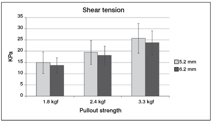
Independently of the applied load, the smaller screw showed higher values of shear stress.
Conclusion:
According to the analysis performed, we observed that the place of highest stress was in the first thread of the lead, close to the head of the screws. Experimental study.
Keywords: Tensile strength, Elasticity, Biomechanics, Quantitative analysis, Qualitative analysis
INTRODUCTION
The pullout strength of pedicle screws is a method widespread in the literature and a way to objectively demonstrate their resistance to axial load. 1 It is one of the most important indexes of interest to manufacturers and surgeons. 2 Studies have been conducted by various researchers in order to evaluate the pullout strength and the factors that can influence it. 3 However , all studies were performed experimentally , without a numerical study on the load and behavior during the pullout of the screw. 2 Maintenance of compression between the bone and the screw threads is the main factor to achieve a rigid fixation with screws in the bone or screws and plaques. 4 According to Define and Vendrame, 5 in general, the pedicle screw is fixed primarily on cancellous bone using a small percentage of cortical bone in the portion of the vertebral pedicle.
The insertion site, the technique used, the geometry and the diameter of the screw can affect the mechanical stability of its fixation. 6 The diameter and shape of the pedicle is an important factor that influences the selection of screw used as implant. 7 The displacement of the screw in the bone tissue is a commonly found clinical problem, being caused by the pullout force. 8 The increased fixation and stability of the implant requires a greater pullout force reducing the incidence of failures by displacement of the screw. 9
The pullout force, when applied on the screw, produces internal tensions. 10 Thus, the photoelasticity has been used in scientific studies to determine the stress distribution in structural systems using qualitative and quantitative analysis by optical elements. 11 The photoelastic analysis allows observing the stress distribution throughout the whole structure, allowing a general perception about the behavior of tensions. 12 This technique shows the location of the tensions within an experimental model through fringes of different colors. It is possible to infer the amount of deformation resulting from a given force by comparing the voltages observed with free hotspot.
The Law of Optical Tension is related to changes in refractive index due to temporary birefringence, as the stress status of the material. This relationship is expressed as:
 |
where fs is the optical constant of matter, in N/mm of fringe; N is the fringe order; and h the thickness of the model. 13 , 14 This technique is widely used in engineering and medicine in problems where there is need for information of stress/ strains in a large structure area, since it is a continuous optical field technique. 15
Therefore, the aim of this study was to determine, analyze and compare the internal tensions of photoelastic models under the influence of 5.2 and 6.2 mm outer diameter USS II type screws, when subjected to pullout efforts using flat transmission photoelasticity.
MATERIALS AND METHODS
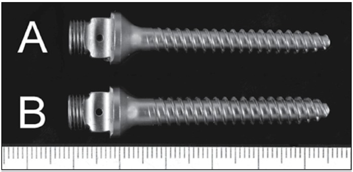
For this study, a 5.2 and a 6.2 mm outer diameter titanium screws 45 mm length, 2.0 mm thread pitch and 8 mm thread height were used in the USS spinal fixation system (Synthes(r)). (Figure 1)
Figure 1. 5.2mm (A) and 6.2mm (B) USS vertebral fixation titanium screws (Synthes(r)).
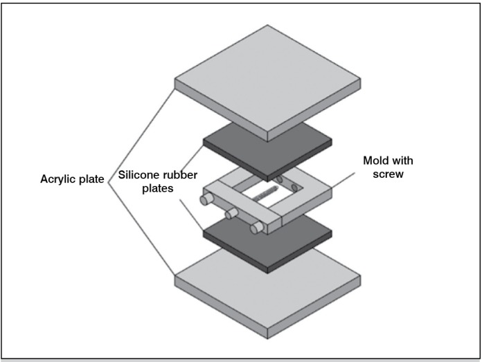
Photoelastic models were made of flexible photoelastic epoxy resin (Polipox(r)). This resin has elasticity modulus of 4.51 MPa and Poisson's coefficient 0.4 (n.t. o coeficiente de Poisson não tem unidade) To build the photoelastic models two standard Teflon(r) (polytetrafluoroethylene) molds, that allowed the reproducibility of dimensions and good surface finishing, were used. The molds were sealed using two acrylic plaques, one on each side. Between each acrylic plaque and the mold a sheet of silicone rubber previously prepared was placed, so that the acrylic plate did not stick to the photoelastic. (Figure 2) The entire assembly was fixed with pressure staples. The finished model was 12 mm thick, 51 mm wide and 58 mm long. For each screw (5.2 and 6.2mm outer diameter) two photoelastic models were made. These models were previously evaluated for the presence of residual stress called edge effect , before application of the pullout strength of the analyzed screws. The photoelastic resin used had an optical constant of 0.375 N/mm of fringe. This constant value was used to calculate the shear stress.
Figure 2. Schematic representation of flexible epoxy photoelastic models.
Photoelastic analysis
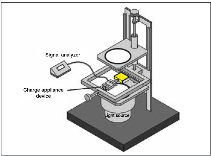
The photoelastic analysis was performed in a transmission polariscope by applying a pullout force on the screw head fixed on the photoelastic model. The model was fixed on an adjustable stand that was positioned horizontally in the polariscope. A load cell was used coupled to a signal analyzer to measure the applied force. (Figure 3) Tensions produced by screws were evaluated qualitatively and quantitatively.
Figure 3. Schematic representation of polariscope used in photoelastic analysis.
Qualitative Analysis
On qualitative analysis of the tensions the starting location for fringe orders in the model, the point of highest stress concentration, the location of higher shear and the behavior of stress distribution by applying different loads were observed.
Quantitative Analysis
In quantitative analysis the shear stress was measured using 1.8, 2.4, and 3.3 kgf pullout strength, recorded through Kratos(r) charge cells, with a 10 kgf capacity. To measure the shear stress on the quantitative analysis a computer program, called Fringes , developed for the automated determination of photoelastic parameters implemented in Matlab(r) 7.0 was used. The methodology is similar to a technique developed by Yoneyama and Takashi, 16 which uses an elliptical polarized white light and color image processing. According to Yoneyama and Takashi, 16 the results reach acceptable values for points with fringe order of 0.5 to 3. The program aims to determine the parameters of isochromatic, eliminating normal reading process. Its advantage is the direct determination of fringe order using only one photoelastic image of the model analyzed. The images of the photoelastic models were captured by a good resolution movie camera, endowed with a good luminosity lens and professional zoom. This camera was directly coupled to the polariscope, images being captured and subsequently transferred to the computer in order to be analyzed by the program. Each photoelastic model was subjected to five images for each load value (1.8 , 2.4 and 3.3 kgf) captured by the camera as follows: the model was placed in the load application system, subjected to different loads and their respective images were captured and, later, his entire load was reduced and the model removed from the charging system. Furthermore, this procedure was performed four times for the other image acquisitions, totalizing 30 images for both photoelastic models. This procedure is important to reduce the experimental error, since small variations in stress distribution models due to high sensitivity of photoelastic resin have been observed. Thus, the average shear stress, corresponding to each group was measured, yielding a more reliable value.
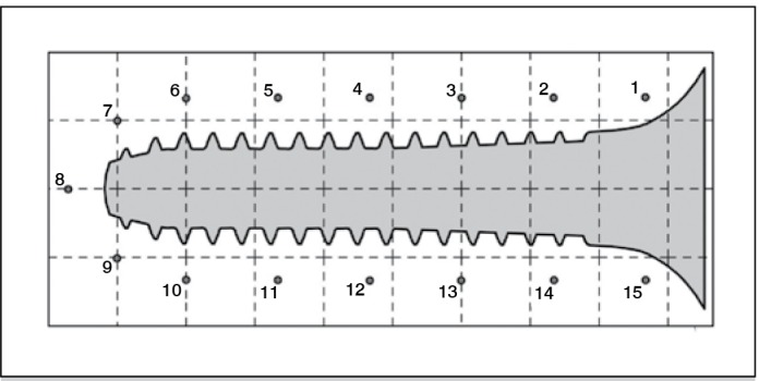
By using the program, the system requested the number of points to be analyzed in the model, the optical constant and the thickness of the model. Therefore, 15 points around screws standing at 1.5 mm away from their outline were analyzed. (Figure 4) The values for optical constant and thickness of the photoelastic model were 0.375 N/mm of fringe and 12.0 mm, respectively. Upon completion of these data, the program requested the image selection of the model to be analyzed.
Figure 4. Scheme of mapping grid used on tests showing the fifteen points analyzed in pedicle screws.
RESULTS
Qualitative Analysis
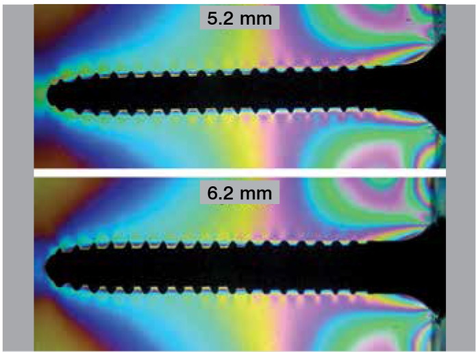
The qualitative analysis showed that the starting location of the fringe orders and the highest concentration point was the first threads of the lead, next to the screw head region. In the region near the tip of the screw, the fringe format was round shaped. Regarding the behavior of stress distribution, it was seen that the higher the applied load, the greater the formation of the fringe along the screw body and consequently the higher the stress in the most critical area (near the bolt head). (Figure 5)
Figure 5. Standard orders of isochromatic fringes obtained in the analysis of 5.2 mm USS pedicle screw applying a load of 3.3 kgf.
Quantitative Analysis
In this analysis, the shear stresses in the 15 points of all photoelastic models were calculated. The average values of maximum shear stress of 5.2 mm and 6.2 mm type USSII pedicle screws are shown in Figure 6.
Figure 6. Mean and Standard deviation of shear tension on both screws submitted to three different pullout strengths.
DISCUSSION
The photoelasticity technique was discovered at the beginning of the 20th century and its application in the area of Orthopedics and Traumatology is still current. This line of experimental research has motivated several articles published in the area, however, there are not yet scientific reports using this technique in the analysis of vertebrate fixation systems components.
Photoelasticity was shown an efficient technique, being capable of evaluating rapidly and satisfactory the sites of greater shear tension through pullout strength. Through this technique photoelastic models with USS screws fused in the photoelastic resin. These models suggest a simulation of a screw integrated with a bone in a chronic postsurgical period, as used in clinical practice in surgeries with vertebrate fixation system. The regular geometry of these photoelastic models allowed the analysis of vertebrate fixation screws, comparing their external diameters. In this case, the geometry possibly did not interfere in the results obtained through the photoelastic analysis.
In the qualitative analysis it was observed that the site of origin of the first orders of the fringe and the most critical region was the first threads of the lead, near the head of the screw. I can also be seen that the shape of the orders of fringe in the region of the tip of type USS II screws was round, in accordance with its geometry.
In the quantitative analysis three load values were used to carry out the screws pullout (1.8, 2.4, and 3.3 kgf). These were low load values, therefore, they only served to generate a stress to screw pullout, since the flexible epoxy resin has high photoelastic sensitivity. The gradual increase of the applied force was important to observe the behavior of the photoelastic model by increasing the number of fringe orders that arose with increasing load, due to increased tension in the model. Thus, with increased pullout strength, the shear stress became more critical, thus there is an increased tendency to loosen the screw. This conclusion is consistent with the research of Fakhouri et al. 17 Regardless the amount of force applied, it was found that the values of shear stress on the 5.0 mm screw were higher than those for the 6.2 mm screw. These results can be explained by geometric and size differences of the screws. The most susceptible shearing sites of the screw are the first threads near the head of the screw, as it is the site of greatest shear stress. Thus, the point of maximum stress concentration was in this region, due to the influence of the screw head and its lower strength and stiffness.
Independently of the screw type, the screw with the lower external diameter is the most susceptible to possible clinical complications according to the dimensions of the screw and the fact that it shows a higher value of shear stress. According to Barber et al., 18 Gayet et al., 19 Kwok et al., 1 and Siqueira et al., 20 the higher the outer diameter of the larger screw, the higher the pullout strength, being, thus, more difficult to pull out the screw. Therefore, the findings obtained in this study are in agreement with these authors.
Barber et al. 18 conclude that the screw performance is also influenced by the geometrical variation, where the higher the screw diameter, the higher the pullout strength. The results of this study showed that the highest concentrations of stress generated on the screws with the application of pullout forces occurred in the first threads, close to the screw head, due to the influence of the screw head.
This result is consistent with the work of Daftari et al. 21 which in mechanical pullout tests, it was observed that the diameter of the pilot hole near the bolt head represented the most important point in its anchorage. With these studies, the authors suggest that the entry point of the screw should be as accurate and fair as possible.
CONCLUSIONS
In photoelastic analyzes the geometry and dimensions of the screws influenced the results. The lower external diameter screw was probably the more susceptible to pullout, due to its higher values of shear stress showed in the assays and because of its size and geometry. In all analyzes, we observed that the point of maximum stress concentration was in the first threads, near the screw head, regardless of the applied load. With the increase in pullout strength, the shear stresses become more critical and therefore, there is an increased tendency to loosen the screw.
Acknowledgments
ACKNOWLEDGEMENTS
This work was performed with financial support from FAPESP and CAPES.
Footnotes
Work performed at the Department de Biomechanics, Medicine and Rehabilitation of the Locomotor System, Faculdade de Medicina de Ribeirão Preto, Universidade de São Paulo, Ribeirão Preto, SP, Brazil, and at Universidade Federal de Uberlândia (Laboratory of Mechanical Projects Professor Henner Alberto Gomide, Faculdade de Engenharia Mecânica), Uberlândia, MG, Brazil.
REFERENCES
- 1.Kwok AW, Finkelstein JA, Woodside T, Hearn TC, Hu RW. Insertional torque and pull-out strengths of conical and cylindrical pedicle screws in cadaveric bone. Spine (Phila Pa 1976) 1996;21(21):2429–2434. doi: 10.1097/00007632-199611010-00004. [DOI] [PubMed] [Google Scholar]
- 2.Zhang QH, Tan SH, Chou SM. Investigation of fixation screw pull-out strength on human spine. J Biomech. 2004;37(4):479–485. doi: 10.1016/j.jbiomech.2003.09.005. [DOI] [PubMed] [Google Scholar]
- 3.Hirano T, Hasegawa K, Takahashi HE, Uchiyama S, Hara T, Washio T, et al. Structural characteristics of the pedicle and its role in screw stability. Spine (Phila Pa 1976) 1997;22(21):2504–2509. doi: 10.1097/00007632-199711010-00007. [DOI] [PubMed] [Google Scholar]
- 4.Andrea CR, Stover SM, Galuppo LD, Taylor KT, Rakestraw PC. Comparison of insertion time and pullout strength between self-tapping and non-self-tapping AO 4. 5-mm cortical bone screws in adult equine third metacarpal bone. Vet Surg. 2002;31(3):189–194. doi: 10.1053/jvet.2002.32398. [DOI] [PubMed] [Google Scholar]
- 5.Defino HL, Vendrame JR. Role of cortical and cancellous bone of the vertebral pedicle in implant fixation. Eur Spine J. 2001;10(4):325–333. doi: 10.1007/s005860000232. [DOI] [PMC free article] [PubMed] [Google Scholar]
- 6.Moran JM, Berg WS, Berry JL, Geiger JM, Steffee AD. Transpedicular screw fixation. J Orthop Res. 1989;7(1):107–114. doi: 10.1002/jor.1100070115. [DOI] [PubMed] [Google Scholar]
- 7.Bernard TN Jr, Seibert CE. Pedicle diameter determined by computed tomography. Its relevance to pedicle screw fixation in the lumbar spine. Spine (Phila Pa 1976) 1992;17(6 Suppl):S160–S163. doi: 10.1097/00007632-199206001-00017. [DOI] [PubMed] [Google Scholar]
- 8.Alobaid A, Arlet V, Busato A, Steffen T. Pull-out strength of the suprapedicle claw construct: a biomechanical study. Eur Spine J. 2005;14(8):759–764. doi: 10.1007/s00586-004-0805-2. [DOI] [PMC free article] [PubMed] [Google Scholar]
- 9.Lill CA, Schneider E, Goldhahn J, Haslemann A, Zeifang F. Mechanical performance of cylindrical and dual core pedicle screws in calf and human vertebrae. Arch Orthop Trauma Surg. 2006;126(10):686–694. doi: 10.1007/s00402-006-0186-6. [DOI] [PubMed] [Google Scholar]
- 10.Browner BD, Jupiter JB, Levine AM, Trafton PG. Skeletal trauma. 2a ed. Philadelphia: Saunders; 1998. [Google Scholar]
- 11.Mahler DB, Peyton FA. Photoelasticity as a research technique for analyzing stresses in dental structures. J Dent Res. 1955;34(6):831–838. doi: 10.1177/00220345550340060601. [DOI] [PubMed] [Google Scholar]
- 12.Rubo JH, Souza EAC. Métodos computacionais aplicados à bioengenharia: solução de problemas de carregamento em próteses sobre implantes. Rev Fac Odontol Bauru. 2001;9(3/4):97–103. [Google Scholar]
- 13.Okada Y, Ikeda S, Fukuda T, Arai F, Negoro M, Takahashi I. Photoelastic stress analysis on patient-specific anatomical model of cerebral artery. IEEE CNF. Micro-Nanomechatronics and human science, 2007. MHS '07. International Symposium on, 2007. 2007. pp. 538–543. [Google Scholar]
- 14.Dally JW, Riley WF. Experimental stress analysis. 3a ed. Nova York: Mcgraw-Hill; 1991. [Google Scholar]
- 15.Hirokawa S, Yamamoto K, Kawada T. A photoelastic study of ligament strain. IEEE Trans Rehabil Eng. 1998;6(3):300–308. doi: 10.1109/86.712228. [DOI] [PubMed] [Google Scholar]
- 16.Yoneyama S, Takashi M. A new method for photoelastic fringe analysis from a single image using elliptically polarized white light. Opt Lasers Eng. 1998;30:441 –4459. [Google Scholar]
- 17.Fakhouri SF, Siqueira DP, Araujo CA, Defino HLA, Shimano AC. Análise fotoelástica de parafuso de sistema de fixação vertebral. Acta Ortop Bras. 2009;17(4):207–210. [Google Scholar]
- 18.Barber JW, Boden SD, Ganey T, Hutton WC. Biomechanical study of lumbar pedicle screws: does convergence affect axial pullout strength? J Spinal Disord. 1998;11(3):215–220. [PubMed] [Google Scholar]
- 19.Gayet LE, Pries P, Hamcha H, Clarac JP, Texereau J. Biomechanical study and digital modeling of traction resistance in posterior thoracic implants. Spine (Phila Pa 1976) 2002;27(7):707–714. doi: 10.1097/00007632-200204010-00007. [DOI] [PubMed] [Google Scholar]
- 20.Siqueira DPP, Fakhouri SF, Araújo CA, Defino HLA, Shimano AC. Análise fotoelástica de um modelo de vértebra humana com parafuso pedicular. Acta Ortop Bras. 2009;17(3):149–151. [Google Scholar]
- 21.Daftari TK, Horton WC, Hutton WC. Correlations between screw hole preparation, torque of insertion, and pullout strength for spinal screws. J Spinal Disord. 1994;7(2):139–145. doi: 10.1097/00002517-199407020-00007. [DOI] [PubMed] [Google Scholar]


