Abstract
Background:
Current methods of closure of the cleft palate result in the formation of scars and impairment of growth. Distraction osteogenesis (DO) might be an effective means to repair or at least reduce the size of wide clefts. This study investigates the biomechanical aspects of this process.
Materials and Methods:
DO simulation was applied to reduce the size of a unilateral hard palate cleft on a three-dimensional (3D) model of the maxilla. For the position of osteotomy lines, two different models were assumed, with the osteotomy line on the affected side in model A and on the intact side in model B. In each model, DO screws were placed on two different positions, anteriorly (models A1 and B1) and posteriorly (models A2 and B2). Displacement pattern of the bony island in each of the four models, reaction forces at DO locations, and von Mises stress were estimated. Mesh generation and data processing were carried out in the 3D finite element analysis package (ABAQUS V6.7-1; Simulia Corp., Providence, RI, USA).
Results:
In model B2, the island moved almost evenly, assuring a more complete closure of the cleft. The most uniform stress distribution was found in model B1.
Conclusion:
The results suggest that the best positions for the DO screw and the osteotomy line for closure of the cleft palate are posteriorly and on the intact side, respectively.
Keywords: Cleft palate, distraction osteogenesis, finite element analysis
INTRODUCTION
Cleft palate is a frequent congenital defect, with an incidence of 1 per 700 to 1,000 live births. The patients experience several problems in speech, feeding, dentition, maxillofacial growth, health status of the middle ear, and social relationships.[1]
The paramount issues aimed at in the treatment of the cleft palate are to achieve reconstruction of normal anatomy and normal speech without confronting maxillofacial growth and to improve the function of the eustachian tube to minimize hearing loss and middle ear infections.[2,3] Current surgical methods comprise suturing palatal mucosal flaps over the cleft without repair of the bony cleft.[1] These techniques, especially if not performed properly, heal with scar contraction, resulting in impairment of later growth and consequently, an unfavorable appearance and dental malocclusion.[1,4,5] In addition, when the tension resulting from the mucosal flaps combines with the lack of bony closure, the risk of dehiscence and oronasal fistula increases.[1] The incidence of oronasal fistula after primary palatoplasty has been reported to be 11 to 25%.[6,7,8] The rate of recurrence is dramatically higher than the primary fistula.[9] The oronasal fistula after palatal surgical repair undoubtedly compromises the above goals and brings about a serious challenge for the treatment team.[9] The tension caused by scar formation may result in velopharyngeal insufficiency, as well.[1]
These sequels often make further invasive procedures obligatory, after some years. Thus, any effort made to preserve normal facial growth would reduce the need for subsequent reconstructive interventions. At present, studies try to create methods that result in fewer complications.[1]
Recently, the induction of new bone formation and soft tissue migration in the area has gained considerable attention. This aim can be achieved by methods such as distraction osteogenesis (DO).[1] The usefulness of DO in both endochondral and membranous bones is well demonstrated. The main superiority of DO is the lengthening of the soft tissue over the bone.[10] Mandibular distraction, expansion of the hard palate, midfacial advancement, and closure of the alveolar cleft are some applications of DO in the craniofacial region.[11,12,13,14,15] It could be assumed that cleft palate repair maybe improved by the application of DO, and DO could be an effective means to at least reduce wide clefts. This will allow cleft closure without a destructive tension.[1,13]
Carls et al. applied DO for lengthening of the hard palate in canine models to introduce a new approach in the treatment of velopharyngeal incompetence.[16] The procedure resulted in 7 to 10 mm of posterior distraction. A similar study has been reported by Ascherman et al.[17]
There are also reports of DO application in closure of the palatal cleft in animal models. Liu et al. carried out a study on 45 dogs to investigate the possibility of suture expansion osteogenesis in the management of bony palatal defects.[13] Tibesar et al. assessed the utility of DO in the closure of hard palate clefts in canine models.[1] Wang et al. successfully applied DO for the closure of palatal bone defects in 15 cats.[18]
In a finite element study, Wang et al. explained the biomechanical aspects of rapid maxillary expansion in a cleft lip and palate model and reported the differences in tissue reactions of normal and cleft palate patients.[19] Gautam et al. launched a similar finite element study to investigate the skeletal and dental effects of rapid maxillary expansion in a patient with unilateral cleft.[20] Pichelmayer and Zemann investigated pitfalls of alveolar cleft closure by osseodistraction.[21]
Up to now, we have found no reports of applying DO in the human hard palate cleft. The hard palate is a unique bone in humans with different biomechanical characteristics. It is very thin, with a distinctive curve and we did not know how it would react to DO. Our hypothesis was that the hard palate cleft can be closed or reduced successfully with DO without any unfavorable outcome. To investigate the biomechanical aspects of this hypothesis, a virtual experiment was designed. The location of the DO screw is the most important issue in this regard that can influence the overall healing process. The purpose of this study was to evaluate stress distribution in the intact side and affected side of the cleft and the movement pattern when the DO device is placed anteriorly or posteriorly in the palate.
MATERIALS AND METHODS
In the present study, DO simulation was applied to reduce the size of a modeled cleft palate. A three-dimensional model (3D) of the maxilla with a unilateral hard palate cleft was created. The 3D model of the maxilla was developed from the computerized tomography (CT) data of a patient with neurological problems and no craniofacial deformity which had been scanned with a 2.0 mm slice thickness. As CT scans just propose the co-ordinate data of cloudy scatter points in the material boundaries, these discrete points may not be proper to produce finite element models directly. Thus, different data-fitting techniques have to be employed to make an approximate mathematical model. The maxilla was modeled through a CT scan image processing of the anatomic data by an image control system (Mimics, Materialise Interactive Medical Image Control System, Leuven, Belgium). The external geometry obtained from Mimics was exported in stereolithography (STL) format. As the STL file could not be processed further to a 3D model due to CAD/CAE (CAD: Computer-aided design, CAE: Computer-aided engineering) inconsistency, SolidView (SolidView/Pro3.53, Solid Concepts Inc.) and SolidWorks (SolidWorks Corp, Concord, Mass) were used with care so as not to lose any important geometric information.
Regarding the higher incidence of left side clefts in previous reports,[22] a unilateral cleft was created on the left side by removing the oral mucosa and bone from the anterior aspect of the alveolar process through the posterior edge of the hard palate, assuming the left lateral incisor to be missed. The created cleft was about 6 mm wide and 50 mm long [Figure 1].
Figure 1.
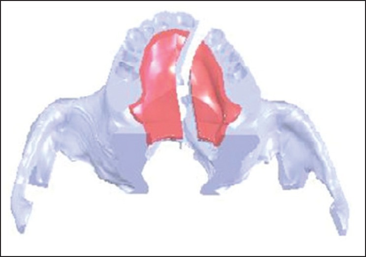
The 3D model of the created cleft
For the position of osteotomy lines, two different models were assumed, one with the osteotomy line and the free bone island (about 8 mm wide and 37 mm long) on the affected side, referred to as model A, and the other with the osteotomy line and bony island (about 13 mm wide and 40 mm long) on the intact side, referred to as Model B [Figure 2]. In both cases, the osteotomy line was created with approximately 5 mm distance from the alveolar crest. These bone islands remained attached to the oral mucosa to simulate the clinical situation. Subsequently, DO was applied to reduce the cleft size. In each model, DO screws were assumed to be positioned on two different locations, one anteriorly and the other posteriorly. Accordingly, four different models were created [Figure 2].
Figure 2.
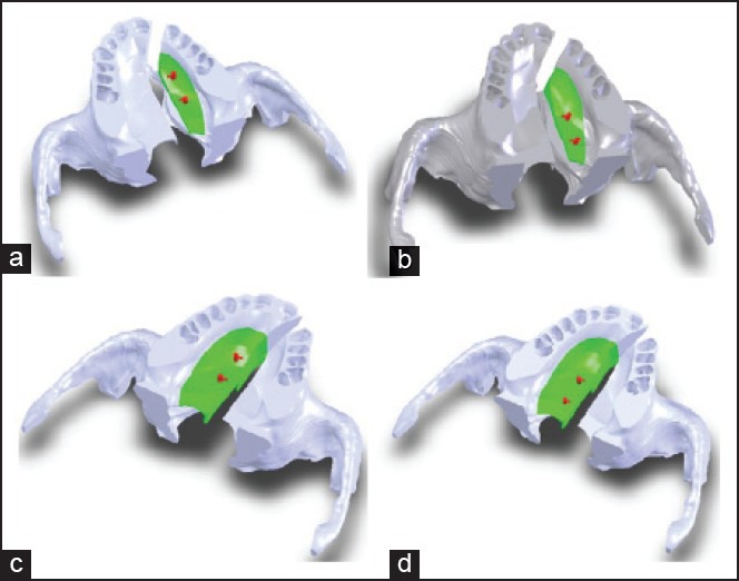
The four created models: a) A1 (osteotomy on the affected side, anterior DO screw), b) A2 (osteotomy on the affected side, posterior DO screw), c) B1 (osteotomy on the intact side, anterior DO screw), d) B2 (osteotomy on the intact side, posterior DO screw)
In our study, mesh generation and data processing were carried out by the 3D finite element analysis package (ABAQUS V6.7-1; Simulia Corp., Providence, USA). All parts of the entire model were treated as homogeneous, isotropic, and linear elastic materials; the properties of these were adapted from the literature [Table 1].[23,24] To the best of our knowledge, tissue properties in cleft palate patients have not been documented. Therefore, in the present study, the material properties were assumed to be similar to those of normal tissues.
Table 1.
Mechanical properties of materials

The nodes at the zygomaticotemporal suture and superior surface of the maxilla were fixed in all directions as boundary conditions. The different anatomical parts were meshed with linear tetrahedral solid elements. Each model comprised approximately 950,000 elements and 200,000 nodes. A linear static analysis with five steps was performed on the prepared 3D solid models. As the bone segments are separated by 1 mm/day in DO, in this virtual study, the segments were displaced 1 mm in each step. To evaluate the course of the cleft closure, the mentioned procedure was repeated five times to achieve 5 mm displacement at screw sites. The movement was accomplished by closing the open screws which were placed at midline to avoid injury to tooth buds.
RESULTS
Displacement pattern of the bony island in each of the four finite element models was achieved. The bony island in model A1 (osteotomy on the affected side with DO screw on the anterior position) moved almost 2.41 mm on the anterior part and 3.4 mm on the posterior, but the maximum movement took place in the middle of the bony island, where the appliance was fixed [Figure 3a]. The bony island in model A2 (osteotomy on the affected side with screw on the posterior position) moved 6.44 mm on the anterior part and 2.26 mm on the posterior part [Figure 3b].
Figure 3.
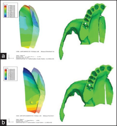
Displacement patterns of the bony island: a) Model A1, b) model A2; the transparent object shows the initial position of the bony island
The bony island in model B1 (osteotomy on the intact side with screw on the anterior position) moved 5.76 mm on the anterior part and 2.44 mm on the posterior [Figure 4a]. The bony island in model B2 (osteotomy on the intact side with screw on the posterior position) moved 4.87 mm on the anterior part and 4.4 mm on the posterior, but the minimum movement was 3.32 mm and took place on the midpalatal region [Figure 4b].
Figure 4.
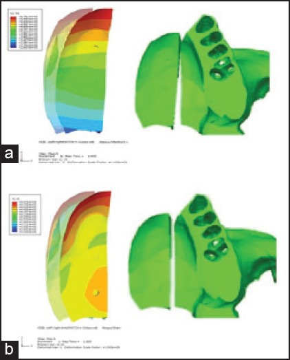
Displacement pattern of the bony island: a) Model B1, b) model B2; the transparent object shows the initial position of the island
The movement of the bony island in all models, except model A1, showed that the rotation center of the bony island was located beyond the posterior edge of the hard palate. The bony island in model B2 shifted more linearly and was expected to achieve a more complete bone closure of the hard palate cleft [Figure 5]. Model A1 displaced quite differently from the other models. The bony island in this model demonstrated a curve-shaped pattern of movement from the anterior to the posterior.
Figure 5.
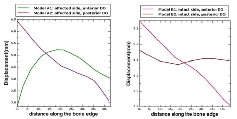
Displacement pattern in different models
Reaction forces at the assumed DO locations were estimated for each model. Maximum force in the first step is illustrated in Table 2. The diagram of force variations versus steps is shown for all models in Figure 6. The minimum force belongs to models A1 and B2 and it increases dramatically in models A2 and B1.
Table 2.
Maximum reaction force in the first step

Figure 6.
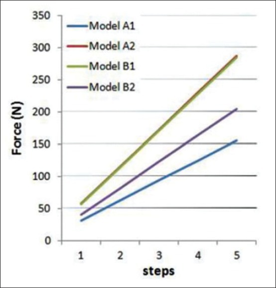
Maximum reaction force in different models
Estimation of von Mises stress on the bony islands was also done [Figure 7]. As shown, maximum von Mises stress value was found around the bone edge and the area in which the appliances were fixed. Figure 8 compares von Mises stress values on the bone edge in different models.
Figure 7.
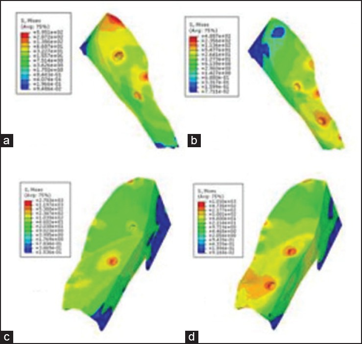
von Mises stress on the bony islands: a) Model A1, b) model A2, c) model B1, d) model B2
Figure 8.
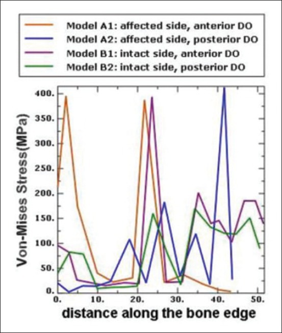
von Mises stress on the bone edges
DISCUSSION
Recently, researchers have focused on presurgical manipulation of surrounding tissues to decrease the need for extensive surgery in cleft palate patients.[25] The well-known orthopedic procedure, DO, can potentially be helpful for this aim. With the help of the method examined in the present study, the two segments of the hard palate might be brought slowly into closer approximation to completely close or reduce the size of the cleft. The gradual tension on the soft tissue stimulates its lengthening and steadily accommodates the new bone. Therefore, achievement of a tension-free closure would potentially decrease the incidence of persistent oronasal fistula and impairment of midfacial growth.
Previous investigators have addressed retruded midface and alveolar clefts with DO techniques in reconstructive procedures of cleft palate patients.[11,12,14] Some animal studies applied DO for lengthening of the hard palate to introduce a new approach in the treatment of velopharyngeal incompetence.[16,17]
There are also reports of DO application in closure of the palatal cleft in animal models.[1,13,18]
To the best of our knowledge, the mechanical aspects of DO application for bony closure of human palatal clefts have not been investigated. In addition, Pichelmayer and Zemann investigated pitfalls of alveolar cleft closure by osseodistraction. They discussed about the placement of the distraction device and concluded that presurgical planning and the construction of the distraction devices maybe modified to reduce problems in such procedures.[21] Therefore, the present study was designed with the aim of evaluating mechanical aspects of DO application and determining the potentially best locations for the osteotomy line and DO screws for closure of the palatal cleft.
The results showed different patterns of displacement and stress distribution among the models. The most favorable pattern was observed in the B2 model, in which the osteotomy line was located on the intact side and the screws were placed posteriorly.
In model A1, the bony island moved on the posterior part more than the anterior, with the maximum movement in the middle of the bony island, where the screws were fixed. Displacement of the bony island in model A1 demonstrated a curved pattern which was completely different from other models.
The maximum movement of the bony island in models A2 and B1 took place on the anterior part, with a progressive descending trend toward the posterior. The only model with roughly even antero-posterior displacement pattern along the bony island was B2, which showed a slightly greater movement on the anterior area. This pattern ensures a more complete bone closure of the cleft. Although the osteotomy line was placed on the cleft side, Wang et al., achieved complete cleft closure by the similar posterior open distractor in cats. This maybe attributable to the different anatomies of the palate in humans and cats.[18] Also they reported that, interestingly, at the end of active distraction, the thin fissure between the two parts disappeared automatically. This shows the healing properties of the live tissues.
Movement analysis in models with osteotomy on the affected side
In this study, a complex of reaction forces of support and joint areas, in addition to the applied force on the bony island, caused deformation and movements. It should also be noted that due to the presence of deformable parts in the model, the rules of free body diagram — used for rigid bodies — is not applicable.
In A1, DO screws were positioned close to the center of the mass of both the maxilla and the island. Although the island displaces together with pulling the soft tissue, the body of the maxilla resists uniformly against movement as a result of the presence of zygoma. Therefore, more displacement occurs in the middle part of the island, where the force is applied, and the entire alveolar process demonstrates movement, although a minor one [Figure 3]. Given that the maxilla is thin in posterior region, the island slightly moves along the Z axis, with the maximum movement in the posteromedial edge [Figure 9a].
Figure 9.
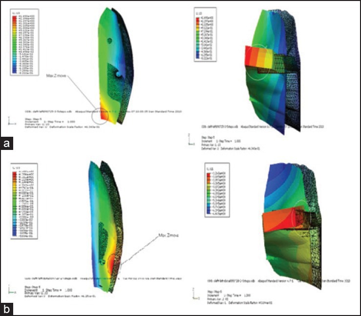
Movement of the island along Z axis: a) Model A1, b) model A2
In A2, the applied force to the bony island first displaces the soft tissue. In the posterior region, as a consequence of the minor mass of the maxilla that causes this part of the maxilla to move more freely, a part of the total force moves the maxilla along the X axis and the island demonstrates less movement, individually [Figure 3]. The movement along the Z axis is larger in the posterolateral edge and the island shows a curve-shaped deformation in the Z-Y plane [Figure 9b]. On the contrary, in the anterior region, the amount of movement of the the bony island is greater, because the larger size of the anterior maxilla and its connection to upper structures do not allow the maxilla to move freely. In this region, greater thickness of the bony island, especially at the lateral border, leads to an insignificant displacement along the Z axis.
Movement analysis in models with osteotomy on the intact side
When the bony island is located in the intact side (B1, B2), the frontal cross-section of the island shows a U-shaped profile that leads to a more uniform movement [Figure 4].
In B1, the amount of movement of the bony island decreases linearly toward the posterior area such that the maximum movement can be detected in the anterior region [Figure 4]. In fact, the island rotates around a center of rotation beyond the posterior palatal edge. This pattern of displacement results in minimum deformation of the internal geometry of the island. Figure 10a demonstrates that the maximum movement along the Z axis occurs at the first molar area, whereas the minimum movement happens in the anterior maxilla at the central incisor area.
Figure 10.
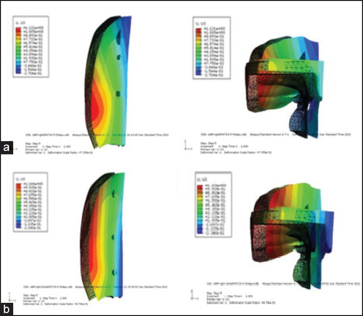
Movement of the island along Z axis: a) Model B1, b) model B2
In model B2, the island moves almost evenly along the X axis [Figure 4]. Analysis of the movement along the Z axis reveals that the amount of movement is different on the medial and lateral areas, and shows a rotation around the Y axis, with the maximum on the lateral side [Figure 10b]. Although B1 and B2 show different patterns of movement along the Z axis, the amount of displacement is almost the same.
Stress analysis
The stress observed in the bony islands results from the resistance against displacement, which is different among the assumed models.
As seen in Figure 7, maximum stress levels were detected around the DO screws and the bone edges; the more the thickness of bone around the DO screws, the less the stress concentration around it. As seen in the models with posterior DO location (A2, B2), the stress concentration around the DO screws increases because of the lesser thickness of bone in the posterior region of the palate. Apart from the stress concentration around the DO screws, von Mises stress distribution is almost similar in A1 and A2, as well as B1 and B2 models due to the geometry of the island. In B1, as the screws were placed in the region with a U-shaped profile, stress distribution was more uniform.
CONCLUSION
The results of the present study suggest that the achievement of complete closure of the palatal cleft by DO is possible by positioning of DO screws posteriorly in the molar region and the osteotomy line on the intact side. The above-mentioned design showed the best pattern of movement of the bony island during the virtual distraction.
Further studies are required to test the clinical aspects of the suggested method. It should also be borne in mind that patients with different cleft types may respond in different ways; therefore, clinicians should always consider the need for customization of the therapy for every patient.
Footnotes
Source of Support: Nil
Conflict of Interest: None declared
REFERENCES
- 1.Tibesar RJ, Moore EJ, Bite U. Distraction osteogenesis for cleft palate closure in a Canine model. Arch Facial Plast Surg. 2005;7:398–404. doi: 10.1001/archfaci.7.6.398. [DOI] [PubMed] [Google Scholar]
- 2.Rohrich RJ, Rowsell AR, Johns DF, Drury MA, Grieg G, Watson DJ, et al. Timing of hard palatal closure: A critical long-term analysis. Plast Reconstr Surg. 1996;98:236–46. doi: 10.1097/00006534-199608000-00005. [DOI] [PubMed] [Google Scholar]
- 3.Rohrich RJ, Byrd HS. Optimal timing of cleft palate closure. Speech, facial growth, and hearing considerations. Clin Plast Surg. 1990;17:27–36. [PubMed] [Google Scholar]
- 4.Bardach J, Kelly KM, Salyer KE. Relationship between the sequence of lip and palate repair and maxillary growth: An experimental study in beagles. Plast Reconstr Surg. 1994;93:269–78. doi: 10.1097/00006534-199402000-00006. [DOI] [PubMed] [Google Scholar]
- 5.Normando AD, da Silva Filho OG, Capelozza Filho L. Influence of surgery on maxillary growth in cleft lip and/or palate patients. J Craniomaxillofac Surg. 1992;20:111–8. doi: 10.1016/s1010-5182(05)80092-7. [DOI] [PubMed] [Google Scholar]
- 6.Amaratunga NA. Occurrence of oronasal fistulas in operated cleft palate patients. J Oral Maxillofac Surg. 1988;46:834–8. doi: 10.1016/0278-2391(88)90044-4. [DOI] [PubMed] [Google Scholar]
- 7.Cohen SR, Kalinowski J, LaRossa D, Randall P. Cleft palate fistulas: A multivariate statistical analysis of prevalence, etiology, and surgical management. Plast Reconstr Surg. 1991;87:1041–7. [PubMed] [Google Scholar]
- 8.Emory RE, Jr, Clay RP, Bite U, Jackson IT. Fistula formation and repair after palatal closure: An institutional perspective. Plast Reconstr Surg. 1997;99:1535–8. [PubMed] [Google Scholar]
- 9.Muzaffar AR, Byrd HS, Rohrich RJ, Johns DF, LeBlanc D, Beran SJ, et al. Incidence of cleft palate fistula: An institutional experience with two-stage palatal repair. Plast Reconstr Surg. 2001;108:1515–8. doi: 10.1097/00006534-200111000-00011. [DOI] [PubMed] [Google Scholar]
- 10.Binger T, Katsaros C, Rücker M, Spitzer WJ. Segment distraction to reduce a wide alveolar cleft before alveolar bone grafting. Cleft Palate Craniofac J. 2003;40:561–5. doi: 10.1597/1545-1569_2003_040_0561_sdtraw_2.0.co_2. [DOI] [PubMed] [Google Scholar]
- 11.Figueroa AA, Polley JW, Ko EW. Maxillary distraction for the management of cleft maxillary hypoplasia with a rigid external distraction system. Semin Orthod. 1999;5:46–51. doi: 10.1016/s1073-8746(99)80042-5. [DOI] [PubMed] [Google Scholar]
- 12.Henkel KO, Ma L, Lenz JH, Jonas L, Gundlach KK. Closure of vertical alveolar bone defects with guided horizontal distraction osteogenesis: An experimental study in pigs and first clinical results. J Craniomaxillofac Surg. 2001;29:249–53. doi: 10.1054/jcms.2001.0240. [DOI] [PubMed] [Google Scholar]
- 13.Liu C, Song R, Song Y. Sutural expansion osteogenesis for management of the bony-tissue defect in cleft palate repair: Experimental studies in dogs. Plast Reconstr Surg. 2000;105:2012–25. doi: 10.1097/00006534-200005000-00016. [DOI] [PubMed] [Google Scholar]
- 14.Liou EJ, Chen PK, Huang CS, Chen YR. Interdental distraction osteogenesis and rapid orthodontic tooth movement: A novel approach to approximate a wide alveolar cleft or bony defect. Plast Reconstr Surg. 2000;105:1262–72. doi: 10.1097/00006534-200004040-00002. [DOI] [PubMed] [Google Scholar]
- 15.Denny A, Kalantarian B. Mandibular distraction in neonates: A strategy to avoid tracheostomy. Plast Reconstr Surg. 2002;109:896–904. doi: 10.1097/00006534-200203000-00011. [DOI] [PubMed] [Google Scholar]
- 16.Carls FR, Jackson IT, Topf JS. Distraction osteogenesis for lengthening of the hard palate, I: A possible new treatment concept for velopharyngeal incompetence: Experimental study in dogs. Plast Reconstr Surg. 1997;100:1635–47. doi: 10.1097/00006534-199712000-00001. [DOI] [PubMed] [Google Scholar]
- 17.Ascherman JA, Marin VP, Rogers L, Prisant N. Palatal distraction in a canine cleft palate model. Plast Reconstr Surg. 2000;105:1687–94. doi: 10.1097/00006534-200004050-00014. [DOI] [PubMed] [Google Scholar]
- 18.Wang DZ, Chen G, Liao YM, Liu SG, Gao ZW, Hu J, et al. A new approach to repairing cleft palate and acquired palatal defects with distraction osteogenesis. Int J Oral Maxillofac Surg. 2006;35:718–26. doi: 10.1016/j.ijom.2006.03.010. [DOI] [PubMed] [Google Scholar]
- 19.Wang D, Cheng L, Wang C, Qian Y, Pan X. Biomechanical analysis of rapid maxillary expansion in the UCLP patient. Med Eng Phys. 2009;31:409–17. doi: 10.1016/j.medengphy.2008.06.011. [DOI] [PubMed] [Google Scholar]
- 20.Gautam P, Zhao L, Patel P. Biomechanical response of the maxillofacial skeleton to transpalatal orthopedic force in a unilateral palatal cleft. Angle Orthod. 2011;81:503–9. doi: 10.2319/070110-367.1. [DOI] [PMC free article] [PubMed] [Google Scholar]
- 21.Pichelmayer M, Zemann W. Alveolar cleft closure by osseodistraction: Pitfalls and troubleshooting. J Craniofac Surg. 2012;23:e72–5. doi: 10.1097/SCS.0b013e31824685d3. [DOI] [PubMed] [Google Scholar]
- 22.Neville BW, Damm DD, Allen CM, Bouquot JE. Developmental defects of the oral and maxillofacial region. In: Neville BW, Damm DD, Allen CM, Bouquot JE, editors. Oral and maxillofacial pathology. 3rd ed. St Louis: Saunders; 2009. p. 3. [Google Scholar]
- 23.Maeda Y, Wood WW. Finite Element Method simulation of bone resorption beneath a complete denture. J Dent Res. 1989;68:1370–3. doi: 10.1177/00220345890680091601. [DOI] [PubMed] [Google Scholar]
- 24.Callister WD., Jr . 7th ed. New York: John Wiley and Sons; 2007. Materials science and engineering: An introduction; p. A6. 10. [Google Scholar]
- 25.Millard DR, Latham R, Huifen X, Spiro S, Morovic C. Cleft lip and palate treated by presurgical orthopedics, gingivoperiosteoplasty, and lip adhesion (POPLA) compared with previous lip adhesion method: A preliminary study of serial dental casts. Plast Reconstr Surg. 1999;103:1630–44. doi: 10.1097/00006534-199905060-00009. [DOI] [PubMed] [Google Scholar]


