Abstract
This paper presents the design and analysis of a handheld manipulator for vitreoretinal microsurgery and other biomedical applications. The design involves a parallel micromanipulator utilizing six piezoelectric linear actuators, combining compactness with a large range of motion and relatively high stiffness. Given the available force of the actuators, the overall dimension of the micromanipulator was optimized considering realistic external loads on a remote center of motion representing the point of expected contact with the sclera of the eye during microsurgery. Based on optimization and workspace analysis, a benchtop version of the micromanipulator was built with a base diameter of 25 mm and a height of 50 mm. It provides a hemispherical workspace of 4.0 mm diameter at the tool tip. The manipulation performance of the constructed manipulator was measured under a lateral load applied at the remote center of motion. The micromanipulator tolerated side loads up to 200 mN.
I. Introduction
Robot-aided micromanipulation has been a focus of research due to its potential for high precision and dexterity [1–3]. Most such platforms have relied on mechanically-grounded teleoperated robots, which can provide tremor filtering and motion scaling [4]. However, there are risks involved with robots that have a large range of motion and high inertia [5]. In addition, these systems do not provide direct force feedback.
As an alternative, a cooperative robot, the Steady Hand, has been introduced [6, 7]. The robotic arm and the surgeon’s hand hold the surgical instrument simultaneously. The robot senses the force applied by the hand and selectively complies, allowing desired motion and suppressing involuntary motion.
Representing another approach, a fully handheld micromanipulator, Micron, has been developed for retinal microsurgery and cell manipulation [3]. It is capable of sensing its own motion and manipulating its end-effector in order to actively compensate involuntary and erroneous motion such as hand tremor. Although Micron provides some advantages in terms of usability, safety, and economy, the system reported in [3] also entails several disadvantages. First, the range of motion is limited to several hundred microns in practice due to the type of piezoelectric bender actuators used. This limited range occasionally causes problems in canceling hand movement with amplitudes of over 100 µm, and limits the capability for other control modes such as semiautomated laser scanning [8]. Furthermore, a manipulator with at least 5 degrees of freedom (5DOF) is desired in order to enable the control system to account not only for the relative motion at the retina, but also for the fulcrum at the entry through the sclera.
A parallel-link mechanism has advantages over a serial-link mechanism for this application, due to its compactness and high rigidity [9]. For this reason all prototypes of Micron have used parallel manipulators [3]. Other research also evinces the potential of parallel micromanipulators for similar applications. Tanikawa and Arai demonstrated a multi-DOF two-fingered parallel micromanipulator which was teleoperated by a two-fingered interface [10]. A bone-mounted miniature 6DOF parallel manipulator was also developed using micromotors and embedded LVDT sensors [5]. However, the overall dimensions of these manipulators reflect the fact that they are not designed for handheld operation. They are mounted to either the table or the skeleton of the patient. A manipulator considerably smaller than these is needed for this application.
A reduction in size of Micron is needed, as the wide manipulator in the previous prototype, caused by the bender actuators, is ergonomically undesirable and tends to obstruct the sight line of the operating microscope [3]. An alternative design by Tan et al., while smaller, has only 3 degrees of freedom [9]. A different type of actuator is needed, therefore, in order to achieve 6DOF operation in a narrower package. The actuator chosen must meet certain specifications for displacement, bandwidth, and force in order to provide successful performance for the system.
In this paper, we propose a six-axis handheld micromanipulator using a new type of a piezoelectric linear actuator. The design of the micromanipulator is optimized and evaluated by simulations to satisfy the requirements of vitreoretinal microsurgery. Based on this design and analysis, a benchtop version of the micromanipulator is constructed and its performance is assessed
II. Design
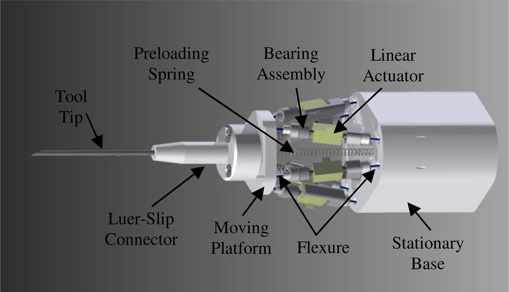
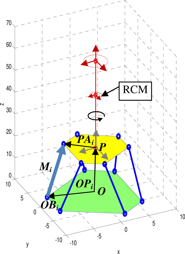
The proposed design for the micromanipulator is a Gough-Stewart platform [11, 12], providing six degrees of freedom, as shown in Figs. 1 and 2. As the actuator for each extensible link, a piezoelectric linear actuator, the SQL-RV-1.8 SQUIGGLE® motor (New Scale Technologies, Inc., USA), is utilized, since it is small enough (2.8 mm × 2.8 mm × 6 mm) and generates a reasonable amount of force (>50gf at 3.3V). The linear stroke of the actuator is limited only by the length of its threaded rod or screw, which can be selected as needed. Based on previous experience, a desired workspace of 4.0 mm diameter is specified. Each link also accommodates a ball bearing assembly on the one end of the screw, to decouple rotational motion and transmit pure translation to the link. Upper and lower ends of the links are connected to the platform and the base, respectively, by polypropylene sutures (#1–0). The sutures play the role of flexure hinges, in lieu of universal joints. In addition, three preloading springs are engaged in order to provide a certain amount of force preload on the motors, which yields consistent linear motion and prevents backlash due to the change in the side of the screw threads that is in contact with the motor. The manipulator must be able to support realistic side loads, as described in Section IV. The manipulator has a male Luer-Slip connector to which various end-effectors can be attached.
Fig. 1.
Design of the proposed micromanipulator.
Fig. 2.
Kinematic configuration of the manipulator.
III. Kinematics
To determine the position and orientation of the tool tip, the inverse kinematics for the parallel micromanipulator is developed. Accordingly, the length of each link for linear actuation is calculated corresponding to the tool tip.
For further analysis, we define the desired 6DOF motion of the tool tip as the combination of two types of translation and one rotation.
Translation in XYZ at the end-effector (3DOF).
Translation in XY at the remote center of motion, at the assumed point of contact with the sclera (2DOF).
Axial rotation of the tool shaft (1DOF).
Specifically, for retinal surgery, the range of motion at the middle of a needle is constrained due to the necessity of working through the sclerotomy [7, 13]. Accordingly, the midpoint of the needle represents a remote center of motion (RCM).
Given the position and orientation by the above categories, the length of each link is determined as defining the corresponding vectors of the links, Mi The vectors are represented by each end of the links with respect to the origin, OAi and OBi, where OBi is pre-defined and fixed on the base.
| (1) |
| (2) |
Here, Ptop (P) is the origin of the moving platform.
In order to determine, OAi, first, the end and the middle positions of the needle are expressed by (3) and (4).
| (3) |
| (4) |
The relative displacements from the initial positions of the needle are denoted by ndei and ndmi in 3D Euclidean space. The length of the needle and the height of the manipulator between the platform and the base are lnd and hm, respectively. In addition, dRCM is given to express the remote center of motion from the platform.
The origin of the platform is then represented by the length of the needle and corresponding vectors, und and Ndend in (5), where und is the normalized form of the vector (6).
| (5) |
| (6) |
| (7) |
Since the normalized vector of the needle can be regarded as a 3D rotational transform of a unit vector, uz, the Euler angles, θx, y,z of the rotation are derived from (8).
| (8) |
| (9) |
| (10) |
Particularly, the angles θx and θy are simply expressed by the components of the normal vector when the axial rotation of the needle, θz, is zero, which is assumed here, because active error compensation for vitreoretinal microsurgery is generally not needed in axial rotation.
| (11) |
Once the rotation matrix is formulated by the angles, the six end positions, OAix,iy,iz of the links on the platform are determined by a homogeneous transform matrix (13).
| (12) |
| (13) |
As a result, the desired lengths of the links are finally determined by the vector of each link, Mi using (2).
IV. Optimization
The overall dimension of the micromanipulator and the preloading springs are optimized in this section. Various approaches have been described for optimization of the dimensions of parallel micromanipulators [14, 15]. These generally assume the overall stiffness of the manipulators to be sufficient to withstand external loads and to achieve high control bandwidth. However, the design space is more limited in the case of micromanipulators. Furthermore, the performance of the manipulator depends greatly on the capabilities of the actuators, as mentioned earlier. For instance, during retinal surgery, they might undergo high external force at the sclera (taken as the remote center of motion) although a relatively small amount of force is required at the end of a needle [13, 16]. Hence, for maintaining the position of the needle even under heavy side load, the load distributed to each actuator by the external force should not exceed the maximum thrust force of the actuator. Otherwise, the actuator stalls and the manipulator cannot cancel hand tremor.
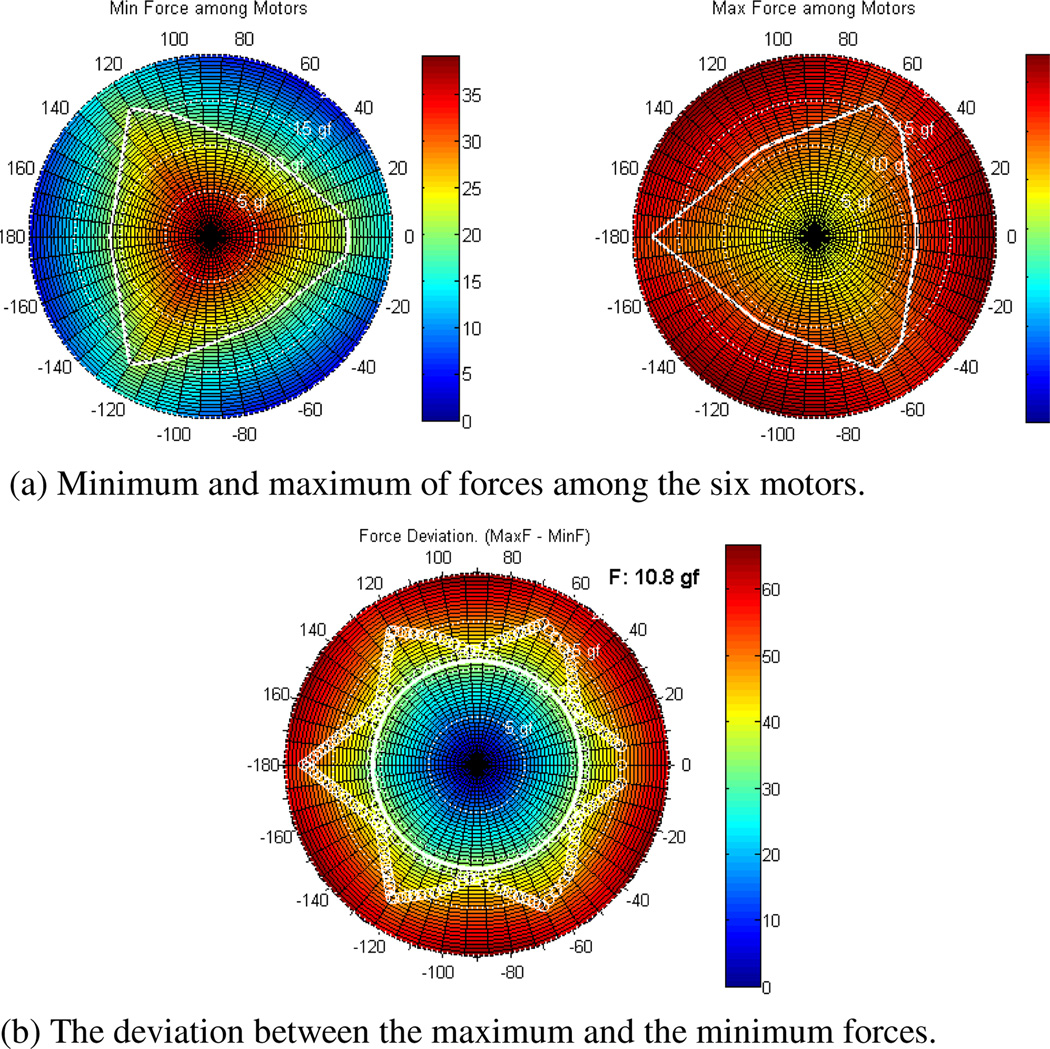
The optimal dimension for the manipulator is therefore determined by the expected side load and the available thrust force. Fig. 3 represents the distribution of the minimum and the maximum forces acting on six motors when a side load from 0 to 20 gf (approximately 200 mN) is applied to the side of the needle (direction of application ranges from 0 to 360°). The deviation between these two extreme forces should be less than the maximum thrust of the actuator.
Fig. 3.
Force distribution with respect to the side load applied at the assumed RCM. The amount of the force and the applying direction are graphically indicated by the radius (0 to 20 gf) and the angle (0 to 180°), respectively, in the polar plots. Given a threshold of the available force on the motors, the tolerable side load is calculated by overlapping two contours from (a).
In addition, a certain amount of preload should be provided on the motors in order to operate consistently. If the direction of the resultant force on the motors changes due to the amount and direction of the side load, backlash on the screw results, degrading control performance.
Overall, the goal is first to minimize the force deviation by optimizing relevant parameters in the geometry of the micromanipulator. Next, by applying appropriate preloading to the motors, the motor should be able to operate always under compression. That is, the minimum force then should be above zero, and the maximum force less than the available thrust force of the motor.
A. Geometrical Parameters
We optimized the geometrical parameters such as diameters of the base and the platform, and the initial height between them. For this procedure, the available thrust force of the motor was set to be 80 gf (800mN), which can be achieved by applying a voltage greater than 3.3 V to the motor. The maximum side load was estimated at 200 mN, based on experiments with porcine retinal tissue ex vivo and rabbit eyes in vivo [13, 16].
In general, a wider manipulator is more robust to side load on the RCM since the larger diameter of the platform leads to smaller force on its supports, based on moment equilibrium. On the other hand, ideally the manipulator should be as narrow as possible for ease of gripping. The dimensions are also constrained by the length of the actuator modules and the need to avoid physical interference between adjacent modules.
Hence, the diameters of the base and the platform and the initial length of the actuating module were optimized under certain constraints. For the optimization, we adopted a numerical approach based on ‘active-set’ algorithm utilizing the Matlab™ function 'fmincon.m' referred to constrained nonlinear optimization since it is too complicated to derive an analytical relationship for a given needle pose. As a nonlinear constraint, the distance between two adjacent joints was assigned and maintained during optimization. In addition, the dimension criteria established upper and lower bounds.
A cost function, f, was defined to minimize the force deviation of the motors at a given needle pose with respect to side load in (14). The side load was applied with the amplitude from 0 to 20 gf (200 mN) and the angle of direction from −π to π around the RCM.
| (14) |
Each force acting on the motors, Fmotori was calculated by the static equilibrium of force and moment at the origin of the platform.
| (15) |
| (16) |
| (17) |
The maximum and minimum forces were then acquired from the forces on the motors. In this step, we assumed the spring preload, Fpreload, to be zero, since it would rarely affect the amount of the deviation.
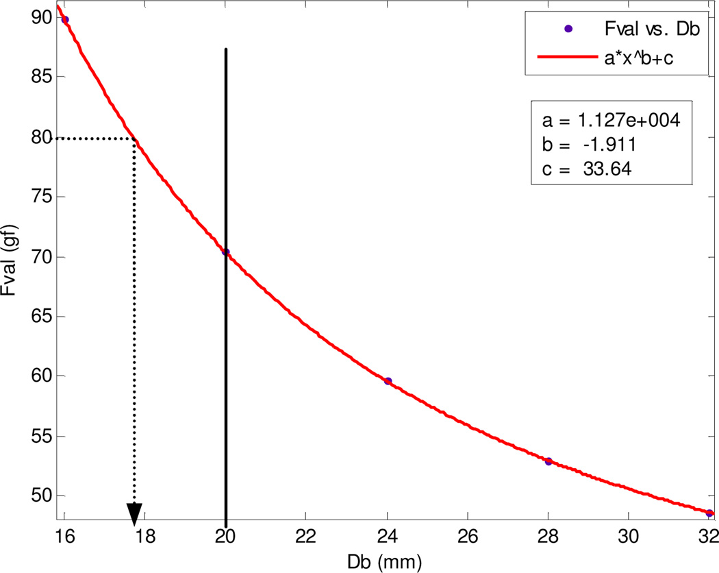
The optimal values tended to be bounded to either the upper or lower boundary of the geometrical parameters. A relationship between the minimum force deviation and the diameter of the base was derived by curve fitting as shown in Fig. 4. The optimal value was selected to be 14 mm and 20 mm for the platform and the base, respectively, which keeps the force deviation below the available thrust force of the motor (80 gf). In addition, the length of the actuating module was set to the minimum length, 22 mm, which was determined by the practicalities of assembling the module. The results of the optimization are shown in Table I.
Fig. 4.
Curve fitting to select the optimal diameter of the base with respect to the force deviation.
TABLE I.
Geometric Optimization
| Condition | Db (mm) | Dt (mm) | Lm (mm) | Fval (gf) |
|---|---|---|---|---|
| Set all upper and lower bounds | 16.00† | 11.00 | 22.00* | 89.95 |
| 20.00† | 13.18 | 22.00* | 70.42 | |
| 24.00† | 16.50 | 22.00* | 59.60 | |
| 28.00† | 18.49 | 22.00* | 52.90 | |
| 32.00† | 20.47 | 23.00 | 48.65 | |
| No lower bound for Lm | 16.00† | 12.52 | 10.00 | 70.44 |
| 20.00† | 14.52 | 13.28 | 62.60 | |
| 24.00† | 16.50 | 16.18 | 56.79 | |
| 28.00† | 18.48 | 18.66 | 52.27 | |
| 32.00† | 20.47 | 21.40 | 48.63 | |
Db = base diameter, Dt = platform diameter, Lm = length of actuator module, and Fval = cost
Value set a upper bound.
Value set at lower bound.
B. Preload
The preload was applied to the screws of the motors by three vertically aligned springs from the platform to the base. These spring forces were defined by the stiffness (k), the initial length (linit.), and the final elongation of the springs from the platform (OS).
| (18) |
A spring with low stiffness would be favorable in this design in order to minimize variation in preload due to movement of the platform. Accordingly, we selected the spring with the lowest stiffness (CI 010EF 14S316, Lee Spring, USA) among commercially available extension springs. This spring has stiffness of 28.2 mN/mm and also allows enough elongation over the dimension of the manipulator.
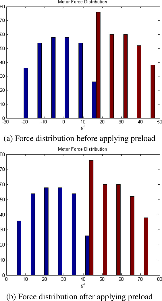
We then found the optimal elongation of the spring, which shifts the force distribution to a desirable regime as shown in Fig. 5. This was achieved since the maximum and the minimum forces were both linearly dependent on the initial elongation. Overall forces were finally distributed in the positive regime (compressive force on the motor) by setting the initial elongation to 18 mm.
Fig. 5.
Force distribution on one of the motors when the side-load is applied. After adjustment, all forces are located in the positive regime.
V. Results
A. Workspace Analysis
Based on the optimization results, the reachable workspaces were reconstructed with respect to the tolerated side load as shown in Fig. 6. For this, we investigated the tolerable side load over hemispherical workspaces of 4.0 mm and 5.0 mm diameter. Fig. 6(a) shows the reachable workspace at 3 different side loads if the available force from the actuators is assumed to be 800 mN. Fig. 6(b) shows the corresponding workspace for an assumed available force of 1000 mN. At each point, the maximum and the minimum forces were computed in the manner described in the optimization (§IV). The forces were then assessed by the criteria of maximum thrust force and overall force range.
Fig. 6.
Attainable workspaces corresponding to three different side loads. Each workspace is reconstructed from the point cloud representing the maximum attainable displacement for the specified side load.
Fig. 6(a) shows that if available force is 800 mN, a side load of 200 mN is tolerated only in a small region of the workspace, whereas 150 mN can be supported throughout. In contrast, if available force is 1000 mN, the manipulator can reach almost the entire specified workspace, even under a side load of 200 mN.
B. Manipulation Performance
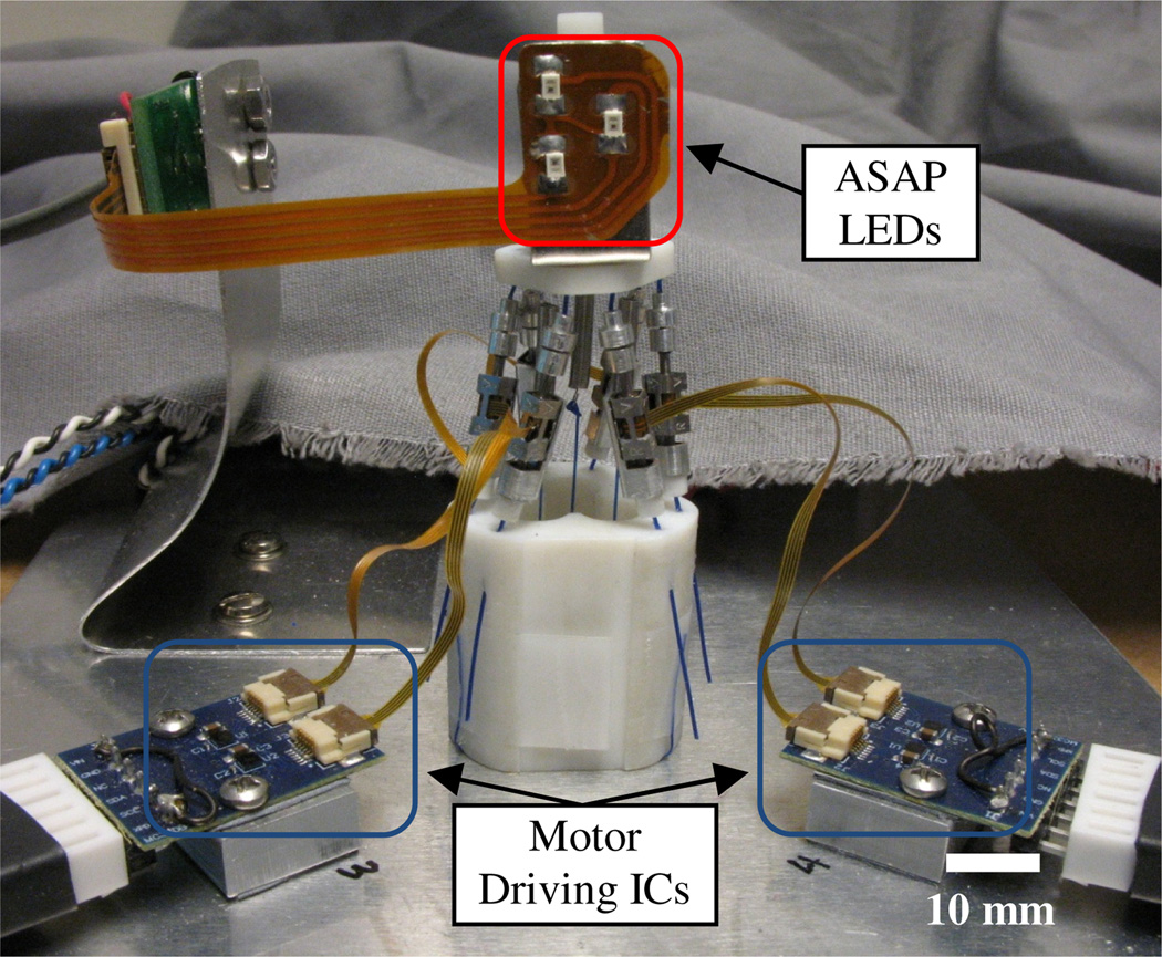
To evaluate the side-load capability, a benchtop version of the micromanipulator was built as shown in Fig. 7. The overall diameter and height of the fabricated manipulator were 25 mm and 50 mm, respectively.
Fig. 7.
A benchtop version of the 6 DOF micromanipulator. LEDs are attached on the moving platform. Each motor is connected to the motor driving IC.
For the experiment, the position of the needle tip was measured by the optical tracking system, ASAP (The Apparatus to Sense Accuracy of Position) mounted on the platform within a 40 mm3 workspace. The externally arranged sensitive detectors (PSDs) detected the IR lights emitted from LEDs on the top platform. The detected signals were finally converted to the position and orientation of the tip at a sampling rate of 2 kHz with noise of less than 10 µm RMS [17]. In addition to the measurement, the needle tip was able to reach the desired pose using a PID controller and the inverse kinematics for finding corresponding lengths of the links.
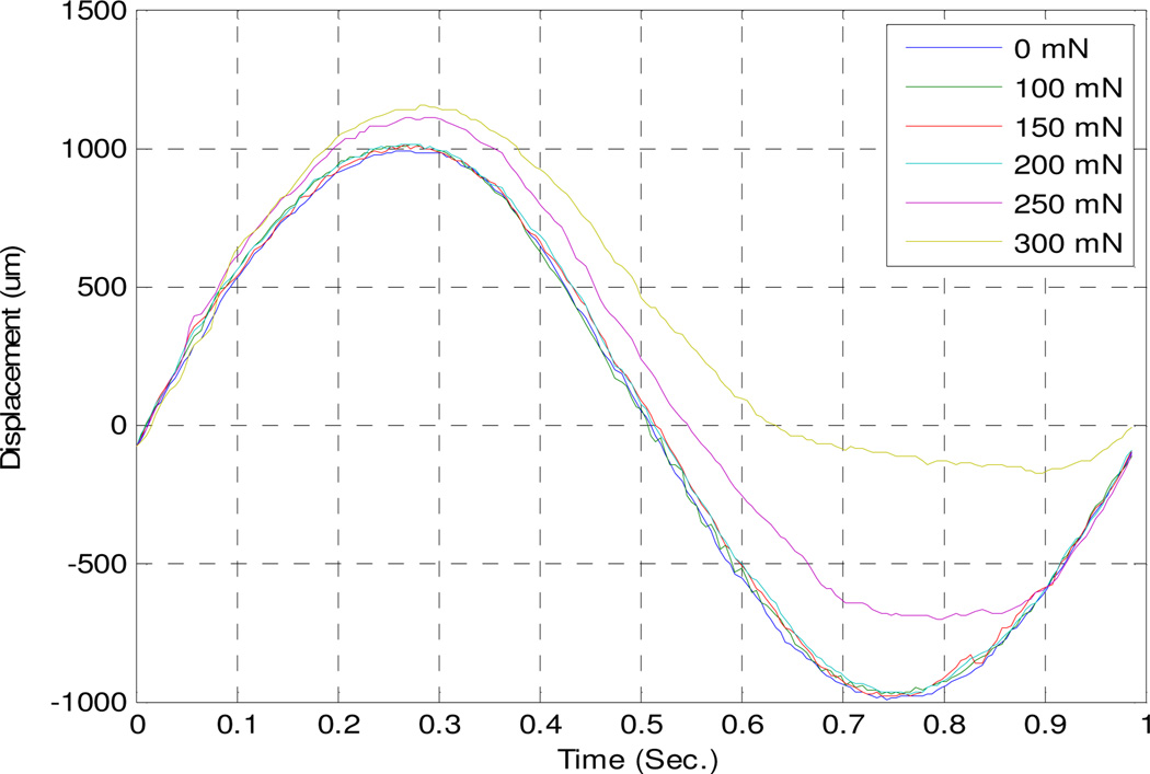
Fig. 8 demonstrates the displacement according to the side load of the range from 0 to 300 mN on the RCM when a sinusoidal input of 1.0 mm was injected to the needle tip. Noticeably, the manipulator tolerates a side load of 200 mN, as expected from the workspace analysis. As the side load exceeds 200 mN, the trajectory of the displacement starts to be distorted considerably. We calculated the RMS error for trajectories in Fig. 8 with respect to the target trajectory without the side load; these are shown in Table II. This result shows that the side-load capability measured by the experiment is consistent with the result from the workspace analysis, especially for the case of 1000 mN maximum thrust force.
Fig. 8.
Displacement measurement with respect to the amount of the side-load.
TABLE II.
RMS Error With Respect to the Ideal Trajectory for Different Side Loads
| 0 mN | 100 mN | 150 mN | 200 mN | 250 mN | 300 mN |
|---|---|---|---|---|---|
| - | 23 µm | 30 µm | 34 µm | 191 µm | 485 µm |
VI. Discussion
The benchtop micromanipulator presented herein successfully provides 6DOF operation and a hemispherical workspace of 4 mm diameter, within a maximum manipulator diameter of 25 mm. The design optimization focused primarily on the amount of side load that can be tolerated, since previous experiments have indicated that the contact force can be considerably higher at the sclera than at the retina [13]. This is of particular importance for this system because the maximum available force decreases as actuator volume decreases, and the force needed to support a given side load increases as manipulator diameter decreases. Using SQL-RV-1.8 SQUIGGLE® motors, the manipulator presented performed successfully under a 200 mN side load within a workspace of 2.0 mm diameter. Simulation indicates that it can be expected to tolerate a 150 mN side load throughout the workspace of 4.0 mm diameter.
A handheld version of the manipulator is now under development. The optimization will be revisited in light of the measured performance of the actuator modules. If larger thrust force is found to be consistently available for the constructed modules, the manipulator can be made more compact, which would be preferable to users. This also has implications for mechanical refinements to the bearing assembly, the dimension of the flexures, and the preloading springs. Finally, the fully handheld 6 DOF micromanipulator will be completed by the integration of additional LEDs on the base for control feedback, and the design of an ergonomic housing for easy grip.
Acknowledgments
This work was supported in part by the National Institutes of Health (grants R01 EB000526 and R01 EB007969).
References
- 1.Dogangil G, Davies BL, Rodriguez y Baena F. A review of medical robotics for minimally invasive soft tissue surgery. Proc. Inst. Mech. Eng. H. 2010 May;vol. 224:653–679. doi: 10.1243/09544119JEIM591. [DOI] [PubMed] [Google Scholar]
- 2.Najarian S, Fallahnezhad M, Afshari E. Advances in medical robotic systems with specific applications in surgery-a review. J. Med. Med. Eng. Technol. 2011 Jan.vol. 35:19–33. doi: 10.3109/03091902.2010.535593. [DOI] [PubMed] [Google Scholar]
- 3.MacLachlan RA, Becker BC, Tabarés JC, Podnar GW, Louis J, Lobes A, Riviere CN. Micron: an actively stabilized handheld tool for microsurgery. IEEE Trans. Robot. 2012 Feb.vol. 28:195–212. doi: 10.1109/TRO.2011.2169634. [DOI] [PMC free article] [PubMed] [Google Scholar]
- 4.Lanfranco AR, Castellanos AE, Desai JP, Meyers WC. Robotic surgery: a current perspective. Ann. Surg. 2004 Jan.vol. 239:14–21. doi: 10.1097/01.sla.0000103020.19595.7d. [DOI] [PMC free article] [PubMed] [Google Scholar]
- 5.Shoham M, Burman M, Zehavi E, Joskowicz L, Batkilin E, Kunicher Y. Bone-mounted miniature robot for surgical procedures: Concept and clinical applications. IEEE Trans. Robot. Autom. 2003 Oct.vol. 19:893–901. [Google Scholar]
- 6.Taylor R, Jensen P, Whitcomb L, Barnes A, Kumar R, Stoianovici, Gupta D, Wang, De Juan E, Kavoussi L. A Steady-Hand robotic system for microsurgical augmentation. Int. J. Robot. Res. 1999 Dec.vol. 1679:1201–1210. [Google Scholar]
- 7.Mitchell B, Koo J, Iordachita M, Kazanzides P, Kapoor A, Handa J, Hager G, Taylor R. Development and application of a new Steady-Hand manipulator for retinal surgery; Proc. IEEE Int. Conf. Robot. Autom; 2007. pp. 623–629. [Google Scholar]
- 8.Becker B, MacLachlan R, Lobes L, Riviere C. Semiautomated Intraocular laser surgery using handheld instruments. Lasers Surg. Med. 2010 Mar.:63–63. doi: 10.1002/lsm.20897. [DOI] [PMC free article] [PubMed] [Google Scholar]
- 9.Tan UX, Win Tun L, Cheng Yap S, Wei Tech A. Design and development of a low-cost flexure-based hand-held mechanism for micromanipulation; Proc. IEEE Int. Conf. Robot. Autom; 2009. pp. 4350–4355. [Google Scholar]
- 10.Tanikawa T, Arai T. Development of a micro-manipulation system having a two-fingered micro-hand. IEEE Trans. Robot. Autom. 1999 Feb.vol. 15:152–162. [Google Scholar]
- 11.Gough VE. Contribution to discussion of papers on research in automobile stability, control and tyre performance. Proc. Auto Div. Inst. Mech. Eng. 1956;vol. 171:392–395. [Google Scholar]
- 12.Stewart D. A platform with six degrees of freedom. Proc. Inst. Mech. Eng. 1965;vol. 180:371–386. [Google Scholar]
- 13.Jagtap AD, Riviere CN. Applied force during vitreoretinal microsurgery with handheld instruments; Proc. 26th Annu. Int. Conf. IEEE Eng. Med. Biol. Soc; 2004. pp. 2771–2773. [DOI] [PubMed] [Google Scholar]
- 14.Liu X-J, Wang J, Gao F, Wang L-P. On the design of 6-DOF parallel micro-motion manipulators. Proc. IEEE/RSJ Int. Conf. Intell. Robot. Sys. 2001;vol. 1:343–348. [Google Scholar]
- 15.Oh K-K, Liu X-J, Kang DS, Kim J. Optimal design of a micro parallel positioning platform. Part II: Real machine design. Robotica. 2005 Jan.vol. 23:109–122. [Google Scholar]
- 16.Kumar R, Berkelman P, Gupta P, Barnes A, Jensen PS, Whitcomb LL, Taylor RH. Preliminary experiments in cooperative human/robot force control for robot assisted microsurgical manipulation; Proc. IEEE Int. Conf. Robot. Autom; 2000. pp. 610–617. [Google Scholar]
- 17.MacLachlan RA, Riviere CN. High-speed microscale optical tracking using digital frequency-domain multiplexing. IEEE Trans. Instrum. Meas. 2009 Jun.vol. 58:1991–2001. doi: 10.1109/TIM.2008.2006132. [DOI] [PMC free article] [PubMed] [Google Scholar]


