Abstract
Injecting clot-busting drugs such as t-PA into tiny vessels thinner than a human hair in the eye is a challenging procedure, especially since the vessels lie directly on top of the delicate and easily damaged retina. Various robotic aids have been proposed with the goal of increasing safety by removing tremor and increasing precision with motion scaling. We have developed a fully handheld micromanipulator, Micron, that has demonstrated reduced tremor when cannulating porcine retinal veins in an “open sky” scenario. In this paper, we present work towards handheld robotic cannulation with the goal of vision-based virtual fixtures guiding the tip of the cannula to the vessel. Using a realistic eyeball phantom, we address sclerotomy constraints, eye movement, and non-planar retina. Preliminary results indicate a handheld micromanipulator aided by visual control is a promising solution to retinal vessel occlusion.
I. Introduction
Retinal vessel occlusion (RVO) occurs when blood flow of a vessel in the eye is blocked by a clot or fat deposits. Sometimes informally referred to as an “eye stroke,” blockages to a branch vessel (BRVO) or central vessel (CRVO) can cause partial or total vision loss, respectively. RVO incidence is one of the leading retinal diseases with 15 million people afflicted worldwide [1]. Incidence of RVO increases with age is especially problematic because it has no effective, proven treatment [2].
Although the gold standard for many retinal conditions, laser treatments are generally ineffective except for treating complications [3, 4]. Two encouraging experimental surgical techniques for treating RVO include radial optic neurotomy and retinal endovascular surgery. Radial optic neurotomy (RON) procedures cut fibrous tissue to relieve pressure on the veins [5]. Retinal endovascular surgery (REVS) cannulates the vein and directly injects clot-dissolving plasminogen activator (t-PA) to remove obstructions [6]. In small-sized comparisons of effectiveness, both procedures have been shown to increase visual acuity, although both procedures experienced side-effects [7]. However, operations on the retina of the eye are difficult to perform because of the small, delicate retinal anatomy. For instance, the internal limiting membrane is only several microns thick and retinal vasculature is often narrower than a human hair. Since involuntary hand movements caused by physiological tremor [8] is significantly larger than the tiny structures being manipulated, ensuring successful outcomes while limiting collateral damage is a challenge with existing instrumentation [9, 10]. The current consensus is that these methods are difficult and have not gained acceptance, but may offer new treatment options in the future pending further study [11, 12].
In order to reduce tremor and provide better positioning during cannulation of retinal vessels, a number of mechanical aids have been proposed. Jensen et al. developed a trackball controlled parallel micromanipulator and successfully cannulated 20–130 μm feline retinal vessels in vivo [13]. Similarly, Weiss successfully used a micromanipulator during ophthalmic surgery to inject t-PA into a human retinal vein, improving patient vision [14]. More recently, the JHU Steady-Hand Eye-Robot with cooperative control between a robot arm and human operator has been used to successfully cannulate small veins in the chorioallantoic membranes of chicken embryos [15]. Dogangil et al. have presented work towards using magnetically controlled micro-bots for retinal drug injection [16]. Ueta et al. introduced a master/slave motion-scaled retinal surgery robot and demonstrated successful cannulations in ex vivo porcine retina [17]. While these assistive robots have focused on damping tremor and increasing positioning precision, all have been fairly bulky and none have addressed the important issue of explicitly preventing collateral damage by placing limitations on tip movement based on the retinal anatomy.
Our previous work introduced a compact, fully handheld micromanipulator, Micron, that used cameras to track the vein and provide motion scaling behavior during cannulation [18]. As a proof-of concept system, we demonstrated successful cannulation of less than 60 μm vessels in “open-sky” ex vivo porcine retina laid out in flat sections. This paper presents a more realistic treatment of the challenges and our proposed solutions for using a handheld micromanipulator for retinal cannulation. In contrast to our previous work, we make use of the JHU eye-phantom [12], consider the issues posed by the sclerotomy constraint, and address the challenges in working in a moving, rotating eye. Specifically, the contributions of this paper are (1) the development a mechanism for protecting the very delicate micropipette during insertion through the sclerotomy (2) the realtime modeling of eyeball movement with feature tracking to compensate for slow vessel detection (3) the use GPU-accelerated stereo algorithms to approximate a 3D model of the eye (4) the provision of visual cues to the operator through the microscope to improve poor depth-localization and (5) the demonstration of preliminary results in ex vivo porcine retina inside the eyeball phantom. The remainder of this paper describes the Micron instrument, our system setup, the approaches used to address challenges in vision-based cannulation, and a concluding discussion.
II. Background
To date, Micron has only been evaluated simply supported by the hand in “open-sky” procedures such as vein tracing or cannulation. In this section, we describe more fully the Micron tool and how we are adapting the tool and the system setup to more realistic “in the eye” scenarios with an eyeball phantom and sclerotomy constraints.
A. Micron Micromanpulator
The current Micron micromanipulator prototype [19] is a handheld 3 degree of freedom (DOF) tool in which the tip actuates independently of the handle (see Fig. 1). Unlike a master/slave system or cooperative robot, Micron is fully handheld and is not attached to a robot arm, which makes it more compact and familiar to surgeons. Three Thunder® piezoelectric actuators arranged in a star pattern at 120° angles move the tip within a 1.5×1.5×0.5 mm range of motion. The tip and handle positions are sensed with custom built optical trackers named ASAP [20]. ASAP tracks three LEDs attached to the shaft of the tip and one on the handle to report 6DOF pose information at 2 kHz with measurement errors of than 10 μm RMS. General tremor compensation is accomplished by driving tip position based on the handle position that has been passed through a shelving low pass filter to remove high frequency movement.
Fig. 1.
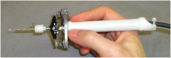
Micron handheld instrument mounted with a micropipette and protection sheath.
B. Eyeball Phantom
As shown in Fig. 2, the JHU eyeball phantom is a hollow, rubber sphere constructed to be the approximate size of a human eyeball. The inside of the phantom is lined with opaque white rubber and painted red and yellow to mimic the retinal structures such as the optic nerve and vasculature. Since painting very small veins is difficult, we glued strands of red-painted painted human hair to mimic very fine vessels found in the retina. The top of the phantom is open for direct line of sight with the microscope, but can be fitted with a vitrectomy lens to simulate lensing effects. For preliminary simplification purposes, we omit the lens from consideration.
Fig. 2.
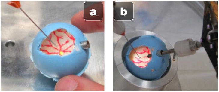
Rubber JHU eyeball phantom. (a) Painted inside illuminated with vitrectomy fiber optic light pipe (b) Micropipette attached to Micron inserted through the sclerotomy port on the right.
For illumination, we use a standard 25 gauge vitrectomy light pipe, which is inserted through the upper left side of the eye with a standard 25 gauge trocar. The Micron instrument is inserted through the upper right side of the eye with a larger 8 gauge port to accommodate the attached micropipette and protective sheath. To simulate the eye rotation in the socket that typically occurs during vitreoretinal surgery, we place the eyeball phantom in a lubricated spherical metal cup. This construction allows the eye to rotate easily and freely during micromanipulation.
C. System Setup
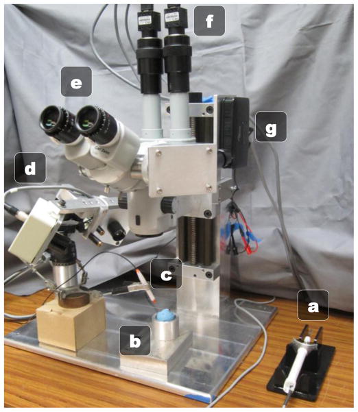
Depicted in Fig. 3, the operator uses Micron under a Zeiss OPMI 1 surgical microscope at a high 25X magnification. An optical bridge allows the attachment of two PointGrey Flea2 cameras to the microscope. The stereo cameras view the same workspace as the operator and capture 1024×768 resolution video at 30 Hz. To display visual cues, such as proximity of the tip to the retina or visual guidance clues during operation, a picoprojector with custom focusing optics is attached to an inverted beam-splitter on the microscope. By injecting images directly into the microscope eyepiece, we can avoid the need for a 3D monitor and allow the surgeon to use the familiar and high-fidelity scope while providing visual cues overlaid on top of the surgical workspace. For cannulation, VitroLife glass micropipettes with an inner diameter of 4–5 μm and bent with a 35° angle are used.
Fig. 3.
Micron cannulation setup: (a) Micron (b) Eye phantom in metal cup (c) Vitrectomy lightpipe (d) ASAP optical trackers (e) Surgical microscope (f) Stereo cameras (g) Image injection system.
D. Unaddressed Challenges in Vessel Cannulation
The goal of retinal cannulation is to inject clot-busting drugs directly into retinal vessels. Unlike previous approaches that focus on mechanical damping or motion-scaling to increase precision, our goal is to use vision to guide the tip towards the vessel while maintaining “forbidden zones” that the tip cannot accidentally enter and cause collateral damage (such as tearing the retina). Compared to our previous “open-sky” work, there are a number of additional challenges and unaddressed issues that arise when working in a more realistic eyeball phantom:
Micropipette insertion into the eyeball through the sclerotomy is problematic, especially as the slightest bump against the trocar can break the fragile angled-tip micropipettes.
Micropipette tracking becomes more challenging with the more vertical positioning and the angled tip.
Vessel localization is significantly more difficult with eyeball movement and variations in light from a moving lightpipe.
Eyeball modeling becomes necessary to determine proximity of the tip to the retina and anticipate movement of the eye.
Furthermore, even with tremor suppression and motion scaling around the vessel, we noticed a distinct tendency during cannulation for the tip of the instrument to push and stretch the vessel to one side, which increases the chances of damaging the vessel and the retina. In the remainder of this paper, we develop solutions to address these issues.
III. Approach
During retinal cannulation, our goal is to create a virtual fixture around the vessel that keeps the tip of the instrument on a smooth approach. Similar to an airplane landing on a runway, we wish to fix the micropipette position directly over the vessel during the approach and puncture to prevent unwanted side stress to the vessel or tears of the surrounding retina. Furthermore, to prevent unwanted piercing of the retina underneath the vessel, we wish to control or otherwise indicate to the surgeon the tip position relative to the retina.
A. Micropipette Protection Sheath
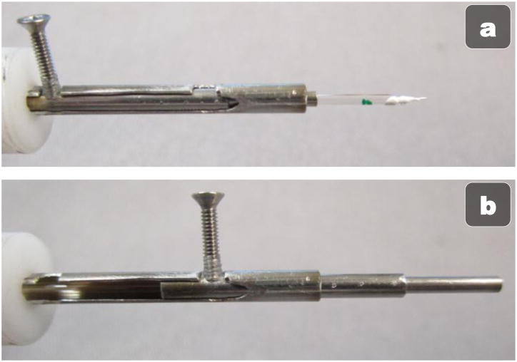
Because the glass micropipette narrows to tens of microns at the tip and has a 35° bend, the tip is very fragile. Thus, insertion of the micropipette through the narrow trocar often results in a broken pipette if the tip brushes the side of the trocar. This is not only inconvenient, but possibly dangerous if any glass shards fall into the eye. Thus, we have designed a sheath to protect the tip during insertion to and removal from the eye (see Fig. 4). A metal, telescoping tube with a pin to extend and retract the tube around the tip of the micropipette has been designed. In the retracted state (Fig 4(a)), the micropipette can be loaded end first into the tube and connected to Micron. A pin then rotates out of a notch to unlock the tube; sliding the pen down the rails extends the sheath over the tip of the instrument (Fig 4(b)) before locking into place once again in a notch further down the tube. The user can then pick up Micron, use the metal guide to safely insert the micropipette into the eye through the trocar, and then use the other hand to retract the tube and unveil the micropipette tip for use inside the eye.
Fig. 4.
Mechanical micropipette protection sheath in the open, unprotected state (a) and the closed, protected state (b).
B. Tracking the Micropipette Tip
Tracking the micropipette is a challenge because of the transparent nature of glass and specular reflections off the curved surface of the micropipette. Because light pipe placement, angle of the micropipette, and lower dynamic range of the cameras, attaching color fiducials to the micropipette as in [18] results in noisy tracking of the micropipette. Instead of trying to minimize the specular reflections and blooming effects of the CCDs, we instead coopt the effect by painting the shaft of the micropipette with white, glossy paint. This brightens the entire micropipette, which stands out clearly against the darker, light-absorbing retina. We use thresholding to obtain a binary image, fast segmentation to isolate the centroid of micropipette [21], and Hu invariant moments to calculate the orientation and the tip position of the segment representing the micropipette. Tracking on both 1024×768 stereo images is performed in realtime at 30 Hz. A short 30 s camera calibration uses the 2D locations of the tracked tip position and the corresponding 3D positions sensed by the optical ASAP system to register the stereo images to the 3D coordinate frame [22]. A least squares iterative registration procedure maintains the registration, adaptively correcting for nonlinearity.
C. Vessel Localization
Our earlier attempts at vessel localization used trained color-matching and segment growing algorithms, which are highly susceptible to changes in illumination [18]. During a vitrectomy, the lightpipe is usually manipulated with the non-dominant hand to control the direction and intensity of light on the desired area of the retina. This dynamic adjustment of the light causes variable lighting conditions and decreases the robustness of color-tracking algorithms. To counteract this effect, we use grayscale-based retinal vessel localization methods. In particular, we find the fast, parallel edge approach of [23] is fairly robust and efficient with 5 Hz update rates. Because the method is targeted for whole fundus images and we operate at high magnification, it returns some noise. We filter out spurious vessel detections with blob-detection and a threshold on the minimum allowable size for a vein.
D. 3D Modeling of the Retina
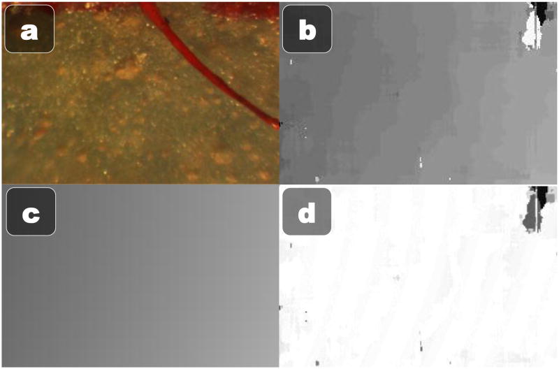
In addition to localizing the vessel, it is important to know the location of the retina in 3D to either enforce depth limits or display relative depths to the operator via visual cues. We have discovered that simple block-matching stereo algorithms produce reasonably consistent, accurate, and fast depth maps if enough care is taken to setup, tweak, and optimize the process. We start out by estimating a homography from the left camera to the right camera using features found on a highly textured planar surface. By warping the left camera view to the right camera view with the estimated homography, we explicitly force the resulting depth map to have an approximately zero mean disparity. Because block-matching only checks in one direction, we explicitly offset one image by half of the maximum level of disparity. We can then use a fairly small 32 maximum levels of disparity, which increases speed. To account for the low texture of the retina, we resize the image to 320×240 and use a large block size of 51×51 pixels. For faster than realtime computation, we use the GPU accelerated block stereo matching algorithm from the OpenCV library [24]. The resulting depth map is still fairly noisy and subject to patches of missing or incorrect depth data. However, since the retina is a smooth section of a roughly spherical eye, we reduce the full depth map to a parametric model by estimating the best fit 3D quadratic to the depth map using RANSAC. The stereo depth map calculation and 3D surface modeling can be performed at 30 Hz thanks to a GPU-accelerated implementation of stereo block matching. See Fig. 5 for an example of the 3D modeling of the eye surface.
Fig. 5.
3D Quadratic parametric modeling of the phantom eyeball. (a) One of the raw stereo frames (b) Estimated depth map (c) 3D quadratic fit estimated with RANSAC (d) Error between the estimated 3D quadratic and the actual depth map (white is no error, darker is higher error).
E. Eyeball Motion Model
One of the most important differences between open-sky or chick egg membrane and real cannulations in the eye is that the sclerotomy constraint where the tool passes through the narrow trocar causes movement of the entire eye. Each manipulation of the instrument causes the eye to rotate slightly in the socket, which means surgeons (and thus the cameras) are always viewing a dynamic scene where the tip and anatomical structures shift around. Surgeons use this phenomenon to naturally pan the view and keep the desired targeted section of the retina centered. However, eyeball motion is problematic because it rapidly invalidates any slower vision algorithms such as the vessel localization that runs at only 5 Hz. A significant amount of movement is possible in 200 ms, especially at high magnifications.
To reduce latencies in the vision system, we model the motion of the eyeball in realtime, which allows for fast, in-between-update motion compensation for slower vision algorithms. Because of the small field of view caused by the high magnification and the relatively small change in depth caused by rotation, we can adequately parameterize the observed motion of the eyeball with a rigid, 2D transformation of translation and rotation. Speeded Up Robust Features (SURF) [25] keypoints are detected in one of the stereo images and matched from an initial frame to the most recent frame. Both the detection of SURF features and the matching is handled by OpenCV on the GPU at 30 Hz using a resolution of 640×480. Once candidate correspondences have been proposed by the brute force GPU matcher, a fast RANSAC estimation algorithm finds the estimated rotation and translation (see Fig. 6). The advantage of RANSAC is it is robust to some occlusion, which is inevitable with the introduction of the micropipette into the eye. A constant velocity Kalman filter on the X translation, Y translation, and rotation acts as a smoothing function and enables predictions of future eye movements.
Fig. 6.
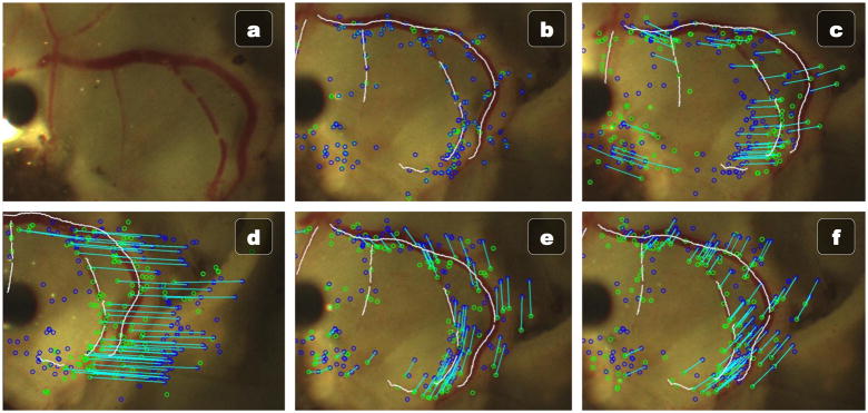
Vessel localization of ex vivo porcine retina with the fast feature-based eyeball motion model. (a) Original image. (b) Initial vessel localization and SURF features. (c–f) Various movements of the eye being successfully tracked in realtime at 30 Hz using only the initial vessel localization from (b).
F. Vision-Based Control
The goal of the control system of Micron is to eliminate high-frequency motion, thereby attenuating tremor, and to reduce drift and positioning error away from the vessel. In order to accomplish this, a virtual fixture coupled with a low-pass filter is enforced to keep the tip of the tracked micropipette always on the vein. Using the output of the vessel localization algorithm and correcting for any subsequent eyeball movement with the eyeball motion model, the nearest point on a vessel from the tip of the instrument is calculated. A ray is cast from the center of the camera to the point on the vessel. The most easily reachable point by Micron given the current pose is selected as the goal point. Thus the virtual fixture constrains the tip of the Micron directly above the vessel using a point that is least likely to cause motor saturation. A low-pass filter is used to remove tremor.
G. Visual Cues via Image Injection
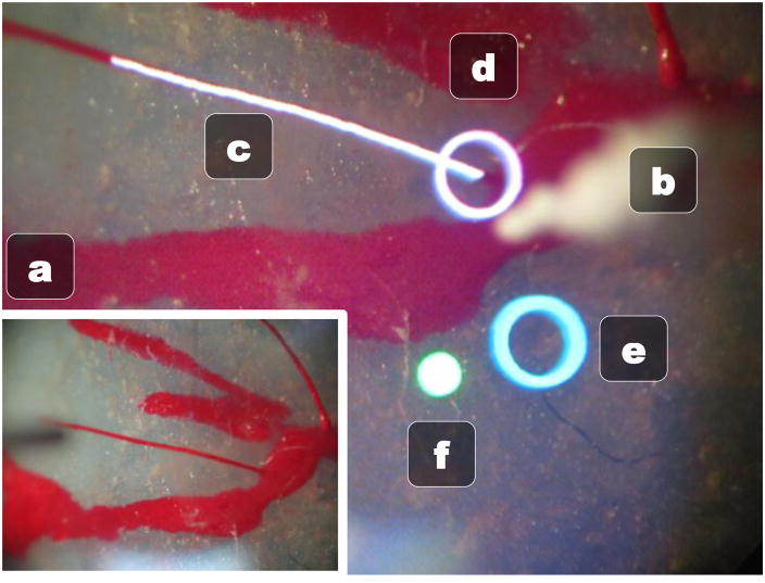
The goal of our retinal cannulation system is to make all the data the surgeon needs available immediately in the eyepiece of the microscope, thus alleviating the need to look away from the operation to a monitor for the status of Micron. In order to do this, we developed an image injection system that uses a picoprojector and custom built optics to overlay visual information over the microscope view by projecting directly into the right eyepiece of the microscope via an inverted beamsplitter. Fig. 7 shows the merging of reality and injected visual cues in the right eye with the information we are currently displaying to the operator. The normal left view is shown in Fig 7(a).
Fig. 7.
Right eye microscope view with image injection displaying visual cues. (a) Normal left eye view without any image injection. (b) Tracked micropipette tip (c) White tracked vessel being targeted for cannulation (d) White circle representing the closest point above the vessel (e) Blue circle showing where the tip of the micropipette would be if Micron was turned off (f) Green status light indicates Micron is on and in the work space.
A red/green circle light (Fig 7(f)) shows the status of Micron so the operator can easily check if the tool is within the workspace and working properly. The result of the vessel localization is displayed in realtime as a white curve overlaid on the vessel targeted for cannulation (Fig 7(c)). The goal position is selected as the nearest point on the vessel based on the tracked micropipette tip (Fig 7(b)) and is denoted by a white circle (Fig 7(d)). A blue circle shows the hand movement, or where the micropipette tip would be if Micron was turned off (Fig 7(e)). To center Micron on the target goal and remain within the range of motion of the actuators, the operator should attempt to maintain the two circles roughly coincident. This allows the eye-hand coordination feedback loop to function even if the tip is under full control by the cannulation system.
IV. Preliminary Results
Although the focus of this paper is on the challenges moving from an “open-sky” cannulation setup to a more realistic one inside an eye-phantom and the solutions we propose to address them, we present some initial results. To simulate a small retinal vessel, we glue a red-painted hair 100 μm wide in the bottom of the eye phantom. To mimic the first steps of a cannulation, the white-painted micropipette with protective sheath is inserted into the eye phantom, the protective sheath uncovered, and the vision-based controller guides the micropipette tip over the vessel. During the approach, the micropipette starts about 2 mm above the vessel and is lowered until it touches the vessel. We measure the deviation of the tip from the center of the vessel during approach and report RMS error with and without vision-based Micron assistance. A single novice user repeated this experiment four times, two with and two without Micron. The approach presented in this paper reduced max error from 298 μm to 73 μm, an overall reduction of 75% (see Fig. 8).
Fig. 8.

History traces of the micropipette tip position during the approach to the vessel (a) unaided and (b) aided.
V. Discussion
In this paper, we have explored the challenges in using vision-based robotic assistance for retinal cannulation tasks and presented preliminary results, demonstrating that handheld micromanipulation is a promising approach. Using a realistic eye phantom with surgical sclerotomy constraints, we have begun to address issues caused by the rotation and movement of the eyeball during micromanipulation. Specifically, we have fused a realtime, GPU-powered motion model of the retina with vessel localization to create virtual fixtures that keep the tip of the instrument centered on the vessel during approach and injection.
Future results include using smaller cannulas, possibly metal microneedles, to eliminate the chance glass fragments. By reducing the diameter of the cannula, a smaller, more standard size gauge trocar can be used. Currently, the sheath protecting the tip is operated manually by the non-dominant hand, so automating the extension and retraction of the tube would save time. We also plan to evaluate the robustness of the quadratic 3D estimations of the retinal surface and enforce temporal consistency by incorporating aspects of the motion model. More importantly, a comprehensive set of experiments with and without Micron’s assistance in cannulating ex vivo porcine retina placed at the bottom of the eye phantom is needed to more fully evaluate the proposed solutions and system.
Acknowledgments
This work was supported in part by the National Institutes of Health (grant nos. R01 EB000526, R21 EY016359, and R01 EB007969), the American Society for Laser Medicine and Surgery, the National Science Foundation (Graduate Research Fellowship), and the ARCS Foundation.
References
- 1.Sophie R, Rachel LM, Ning C, Lyndell L, Jie Jin W, Paul M, Jonathan WK, Hiep N, Tien YW. The prevalence of retinal vein occlusion: pooled data from population studies from the United States, Europe, Asia, and Australia. Ophthalmology. 2010;117:313–319.e1. doi: 10.1016/j.ophtha.2009.07.017. [DOI] [PMC free article] [PubMed] [Google Scholar]
- 2.Nilufer B, Cosar B. Surgical treatment of central retinal vein occlusion. Acta Ophthalmologica. 2008;86:245–252. doi: 10.1111/j.1755-3768.2007.01144.x. [DOI] [PubMed] [Google Scholar]
- 3.Hayreh SS, Rubenstein L, Podhajsky P. Argon laser scatter photocoagulation in treatment of branch retinal vein occlusion: a prospective clinical trial. Ophthalmologica. 1993;206:1–14. doi: 10.1159/000310354. [DOI] [PubMed] [Google Scholar]
- 4.T. C. V. O. S. Group. Evaluation of grid pattern photocoagulation for macular edema in central vein occlusion. M report. Ophthalmology. 1995;102:1425–33. doi: 10.1016/s0161-6420(95)30849-4. [DOI] [PubMed] [Google Scholar]
- 5.Opremcak EM, Rehmar AJ, Ridenour CD, Kurz DE, Borkowski LM. Radial optic neurotomy with adjunctive intraocular triamcinolone for central retinal vein occlusion: 63 consecutive cases. Retina. 2006;26:306–13. doi: 10.1097/00006982-200603000-00009. [DOI] [PubMed] [Google Scholar]
- 6.Weiss JN, Bynoe LA. Injection of tissue plasminogen activator into a branch retinal vein in eyes with central retinal vein occlusion. Ophthalmology. 2001;108:2249–2257. doi: 10.1016/s0161-6420(01)00875-2. [DOI] [PubMed] [Google Scholar]
- 7.Yamamoto T, Kamei M, Sakaguchi H, Oshima Y, Ikuno Y, Gomi F, Ohji M, Tano Y. Comparison of Surgical Treatments for Central Retinal Vein Occlusion; Ron Vs. Cannulation of Tissue Plasminogen Activator Into the Retinal Vein. Retina. 2009;29:1167–74. doi: 10.1097/IAE.0b013e3181a46a5e. [DOI] [PubMed] [Google Scholar]
- 8.Singh SPN, Riviere CN. Physiological tremor amplitude during retinal microsurgery. Proc Northeast Bioeng Conf. 2002:171–172. [Google Scholar]
- 9.Tang WM, Han DP. A study of surgical approaches to retinal vascular occlusions. Archives of Ophthalmology. 2000;118:138–143. doi: 10.1001/archopht.118.1.138. [DOI] [PubMed] [Google Scholar]
- 10.Tsilimbaris MK, Lit ES, D’Amico DJ. Retinal microvascular surgery: a feasibility study. Invest Ophthalmol Vis Sci. 2004;45:1963–68. doi: 10.1167/iovs.03-0874. [DOI] [PubMed] [Google Scholar]
- 11.Joussen AM, Gardner TW, Kirchhof B. Retinal vascular disease. Springer Verlag; 2007. [Google Scholar]
- 12.Holtz F, Spaide RF. Medical retina. Springer; 2007. [Google Scholar]
- 13.Jensen PS, Grace KW, Attariwala R, Colgate JE, Glucksberg MR. Toward robot-assisted vascular microsurgery in the retina. Graefe’s Archive for Clinical and Experimental Ophthalmology. 1997;235:696–701. doi: 10.1007/BF01880668. [DOI] [PubMed] [Google Scholar]
- 14.Weiss JN. Treatment of central retinal vein occlusion by injection of tissue plasminogen activator into a retinal vein. Am J Ophth. 1998;126:142–144. doi: 10.1016/s0002-9394(98)00086-5. [DOI] [PubMed] [Google Scholar]
- 15.Fleming I, Balicki M, Koo J, Iordachita I, Mitchell B, Handa J, Hager G, Taylor R. Cooperative robot assistant for retinal microsurgery. MICCAI. 2008;5242:543–550. doi: 10.1007/978-3-540-85990-1_65. [DOI] [PubMed] [Google Scholar]
- 16.Dogangil G, Ergeneman O, Abbott JJ, Pané S, Hall H, Muntwyler S, Nelson BJ. Toward targeted retinal drug delivery with wireless magnetic microrobots. Proc IEEE Intl Conf Intelligent Rob Sys. 2008:1921–1926. [Google Scholar]
- 17.Ueta T, Yamaguchi Y, Shirakawa Y, Nakano T, Ideta R, Noda Y, Morita A, Mochizuki R, Sugita N, Mitsuishi M. Robot-Assisted Vitreoretinal Surgery: Development of a Prototype and Feasibility Studies in an Animal Model. Ophthalmology. 2009;116:1538–1543. doi: 10.1016/j.ophtha.2009.03.001. [DOI] [PubMed] [Google Scholar]
- 18.Becker BC, Voros S, Louis J, Lobes A, Handa JT, Hager GD, Riviere CN. Retinal vessel cannulation with an image-guided handheld robot. Conf Proc IEEE Eng Med Biol Soc. 2010:5420–5423. doi: 10.1109/IEMBS.2010.5626493. [DOI] [PMC free article] [PubMed] [Google Scholar]
- 19.MacLachlan RA, Becker BC, Tabares JC, Podnar GW, Louis J, Lobes A, Riviere CN. Micron: an Actively Stabalized Handheld Tool for Microsurgery. IEEE Trans Robot. doi: 10.1109/TRO.2011.2169634. accepted. [DOI] [PMC free article] [PubMed] [Google Scholar]
- 20.MacLachlan RA, Riviere CN. High-speed microscale optical tracking using digital frequency-domain multiplexing. IEEE Trans Instrum Meas. 2009;58:1991–2001. doi: 10.1109/TIM.2008.2006132. [DOI] [PMC free article] [PubMed] [Google Scholar]
- 21.Bruce J, Balch T, Veloso M. Fast and inexpensive color image segmentation for interactive robots. 2000. [Google Scholar]
- 22.Hartley R, Zisserman A. Multiple View Geometry in Computer Vision. Cambridge, UK: Cambridge University Press; 2003. [Google Scholar]
- 23.Can A, Shen H, Turner JN, Tanenbaum HL, Roysam B. Rapid automated tracing and feature extraction from retinal fundus images using direct exploratory algorithms. IEEE Trans Inform Technol Biomed. 1999;3:125–138. doi: 10.1109/4233.767088. [DOI] [PubMed] [Google Scholar]
- 24.OpenCV Library. Available: http://opencv.willowgarage.com/
- 25.Bay H, Ess A, Tuytelaars T, van Gool L. SURF: Speeded Up Robust Features. Proc IEEE Computer Vision and Pattern Recognition. 2008;110:346–359. [Google Scholar]


